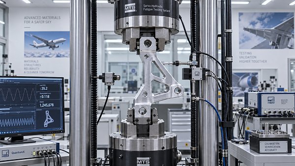
What Documents Prove a Precision Machining Supplier Can Hold Tolerance?
Publication Date
author
A machining quote can promise “±0.01 mm,” yet that statement alone does not prove the supplier can repeatedly produce parts within that limit. The risk becomes visible when a prototype passes inspection but a later production lot shows positional drift, inconsistent bore sizes, poor surface finish, or assembly interference. In aerospace, medical, motion-control, and automation work, one out-of-tolerance feature can stop an entire build.
So, what documents prove a precision machining supplier can hold tolerance? Look for a connected evidence trail: a relevant quality-system certificate, controlled drawing review, calibrated measurement records, a documented inspection plan, first article evidence, process capability data where production volume supports it, and lot-level material and inspection traceability. No single certificate proves every part will conform. The strongest proof is that these documents agree with the actual drawing, material, process route, and inspection results.
Start by matching the document to the tolerance risk
A supplier may hold a straightforward external diameter to a tight limit while struggling with a deep internal bore, a thin-wall part that distorts after machining, or a positional tolerance that depends on several datum relationships. Before requesting paperwork, identify which requirements drive function:
- Dimensional tolerances on critical diameters, widths, depths, and wall thicknesses
- Geometric tolerances such as position, profile, flatness, perpendicularity, concentricity, and runout
- Surface texture, burr limits, edge-break requirements, and cosmetic restrictions
- Thread form, thread depth, and functional gauge requirements
- Material condition, heat treatment, coating, passivation, or other post-machining processes
- Datum scheme and the functional method by which the part is located during inspection
This matters because the documents should demonstrate control of the specific risk. A general inspection report that lists a few outside dimensions does not establish capability for a profile tolerance across a complex five-axis surface. Likewise, a calibration certificate for a micrometer does not prove that the supplier can inspect a true position callout reliably.
A quality-system certificate is a starting point, not final proof
Ask for the current quality-management certificate and verify its scope. ISO 9001 commonly indicates that the supplier operates a documented quality system. For work in regulated or high-consequence sectors, customers may also require a certificate aligned with the applicable sector standard, such as AS9100 for aviation and aerospace supply chains or ISO 13485 for medical-device quality systems.
The certificate should identify the certified legal entity, facility address, standard, certification body, scope, and validity dates. A certificate belonging to a parent company or a different production site does not automatically cover the machining facility that will make the parts. Nor does certification confirm that every machine, programmer, inspector, and subcontracted process is suitable for the drawing in question.
Use it to establish that document control, corrective action, traceability, internal audit, and nonconforming-product procedures exist. Then request the production-specific evidence that shows those procedures were applied.
Drawing review and feasibility records reveal whether the supplier understood the requirement
Before cutting material, a capable supplier should review the released drawing, revision level, model, specifications, and purchase-order requirements. The record may be called a contract review, feasibility review, manufacturing review, or engineering review. Names vary; the useful content does not.
A meaningful review identifies ambiguous callouts, conflicting dimensions, missing datum references, unmeasurable requirements, unusual inspection needs, and process constraints. For example, a supplier may flag that a tight position tolerance requires a datum simulator or that anodizing growth affects a final bore size. That is not a warning sign by itself. It is often evidence that the supplier is preventing a late-stage dispute.
Watch for a different problem: a supplier that accepts a complex drawing without questions but cannot show how the part will be fixtured, machined, or inspected. Capability begins with correct interpretation. A shop cannot consistently hold a tolerance it has not translated into a controlled process.
Calibration records must cover the measurement method actually being used
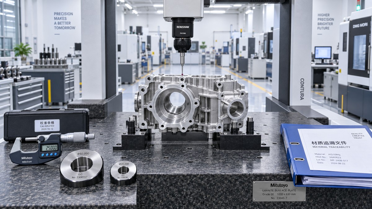
Inspection results are only as credible as the measurement system behind them. Request a calibration status list or certificates for the equipment intended for critical features: calipers and micrometers for simple sizes, height gauges and bore gauges for precision diameters, CMMs for complex geometry, optical systems for small features, surface testers for roughness, and functional gauges for threads or mating interfaces.
Calibration documents should show equipment identification, calibration date, due date, status, and traceability to recognized standards. Where relevant, ask whether calibration was performed by a competent internal system or an external laboratory with appropriate accreditation. The point is not to collect paperwork for every hand tool. The point is to confirm that the proposed inspection method is controlled and suitable for the tolerance.
For close limits, calibration alone is insufficient. The supplier should also consider measurement system analysis, often documented through gauge repeatability and reproducibility studies. A measuring device may be calibrated yet still provide inconsistent results when different inspectors use it, when a part is difficult to locate, or when temperature changes affect the reading. If measurement variation consumes too much of the tolerance band, the final report can look precise without being dependable.
Ask for the inspection plan before relying on the final report
The inspection plan explains how conformity will be verified. It may appear as a control plan, inspection instruction, quality plan, router, or operation sheet. Unlike a polished final inspection report, this document exposes the practical method: where inspection occurs, which features are checked, what tools are used, how often measurements are taken, and what happens when a result falls outside the allowed range.
For a part with tight tolerances, a useful plan should connect the drawing characteristic to a method. A critical bore might be checked with a certified air gauge or bore gauge at a specified temperature. A positional tolerance may require CMM measurement against defined datums. Flatness might be measured on a controlled reference surface with a stated setup. If the plan merely says “inspect per drawing,” it provides little evidence that difficult characteristics have been considered.
Questions that expose weak inspection planning
- Which characteristics are treated as critical, and why?
- Will the part be inspected in the same datum condition in which it functions?
- Is inspection performed after rough machining, after finishing, and after outside processing where needed?
- Are sampling rules appropriate for the part’s risk and order quantity?
- Can the chosen instrument resolve the required tolerance with adequate margin?
- Who reviews an out-of-specification reading, and how is affected material contained?
A clear answer to these questions is often more informative than a broad claim of “100% quality control.” Full inspection may be necessary for selected features, but it still must use a valid method, correct datums, and controlled records.
First article inspection confirms the first controlled output
A first article inspection report (FAI) is one of the most useful documents when qualifying a new part, revising a design, changing a machine program, or moving production to another facility. The report maps drawing requirements to measured results on an actual part produced through the intended route. In aerospace programs, an AS9102-style first article package may be requested; other industries may use their own format.
A strong first article package normally includes the ballooned drawing, characteristic numbers, actual measured values, measurement units, inspection equipment or method, material identification, and evidence for required special processes. It should also show the applicable drawing revision. A report with only “pass” entries and no values offers less traceability than one with recorded results.
Do not treat an FAI as permanent proof. It demonstrates conformity at a defined time under a defined process. It must be revisited when the design, material source, manufacturing method, tooling, inspection approach, outside processor, or production location changes in a way that could affect the part.
Process capability data distinguishes a successful sample from a stable process
For recurring production, request capability evidence for the features that matter most. This is usually presented as statistical process control (SPC) charts and capability indices such as Cp and Cpk. These values can help show whether process variation fits within the specification and whether the process is centered within the tolerance range.
Capability data is only useful when its context is visible. Review the characteristic measured, specification limits, number of observations, lot or time period, production conditions, measurement method, and whether the process was stable during collection. A high-looking index from a short engineering run may not represent normal production. It may exclude tool changes, material variation, operator changes, warm-up effects, or post-processing variation.
For low-volume, one-off, or highly customized components, formal Cpk studies may not be practical. In those cases, detailed setup verification, in-process results, repeated dimensional checks across the lot, and evidence of an appropriate machining strategy may be more relevant. Do not reject a supplier simply because a prototype job lacks production SPC; ask for evidence proportional to the production situation.
Material and process traceability protect tolerances after machining
Parts can meet dimensions when they leave the machine and still fail after heat treatment, plating, anodizing, welding, passivation, or other outside processing. Material properties and post-machining processes affect distortion, corrosion resistance, hardness, surface condition, and final dimensions. This is why a dimensional report without traceability is incomplete for many critical parts.
Request material test reports or certificates of conformance that identify the material grade, heat or lot number, and applicable specification where required. The supplier should be able to connect that material lot to the work order and finished-part lot. When outside processing is involved, retain certificates that identify the process, applicable specification, batch, and part or lot reference.
For tolerances affected by finishing, clarify the inspection sequence. A bore measured before coating may not meet the final drawing requirement after coating. A thin component that is flat before heat treatment may warp afterward. The control plan should state whether final acceptance occurs after the dimension-changing process, not merely before it.
Nonconformance and corrective-action records show how the supplier responds under pressure
Every manufacturing system produces occasional deviations. The important question is whether the supplier can identify, contain, document, and correct them without allowing questionable parts into the shipment. Ask how nonconforming material is segregated, how rework is controlled, and whether concessions or deviations require customer approval.
You do not need access to confidential records from unrelated jobs. However, the supplier should be able to explain its corrective-action process and provide relevant documentation when a deviation affects your order. For ongoing programs, review recurring defect categories, corrective actions related to critical operations, and the method used to verify that the action worked. A corrective action that changes a tool offset but does not address fixture movement, tool wear, program logic, or inspection error may only hide the underlying cause.
Build a document request around the stage of supplier qualification
Early evaluation does not require a complete dossier for every drawing. Begin with the quality certificate, a capability discussion tied to the hardest features, sample calibration evidence for the intended inspection equipment, and a proposed inspection approach. Before production release, require the documented drawing review, first article package, material traceability plan, and any required special-process approvals.
During routine production, receive lot-specific inspection documentation, material and process certifications where specified, and capability or SPC evidence for agreed critical characteristics. The purchase order and quality clauses should state which records are required, the revision to be used, the retention period where relevant, and whether records must accompany shipment or be available on request.
The practical standard is simple: documents should let an engineer trace a delivered feature back to the drawing requirement, the measurement method, the inspection result, the manufacturing lot, and the material or outside process that may have affected it. When that chain is complete, a supplier’s tolerance claim becomes an engineering decision supported by evidence rather than a promise on a quotation.
Search News
Hot Articles
- Carbon Fiber StructuresHow to Specify Aerospace Carbon Fiber Assemblies for Lightweight, Load-Bearing PartsJul 11, 2026
- Machine VisionXiaomi, Alibaba DAMO Academy Drive Open-Source Robotics Model Ecosystem, Lowering Algorithm Development Barriers for Overseas SMEs Adopting Chinese Robotics SolutionsMar 30, 2026
- Cobots & ArmsShanxi 'AI+' Conference Showcases Embodied Intelligence with Multinational Buyer Engagement: Key Industry ImplicationsMar 30, 2026
Popular Tags
Recommended News
 Jul 11, 2026How to Specify Aerospace Carbon Fiber Assemblies for Lightweight, Load-Bearing PartsAerospace carbon fiber assemblies: learn how to specify laminate design, load data, joining methods, and inspection controls for lighter, reliable load-bearing aerospace parts.Elena Rostova (UAV Systems Researcher)
 Mar 30, 2026Xiaomi, Alibaba DAMO Academy Drive Open-Source Robotics Model Ecosystem, Lowering Algorithm Development Barriers for Overseas SMEs Adopting Chinese Robotics SolutionsXiaomi & Alibaba DAMO Academy's open-source robotics models lower algorithm barriers for global SMEs. Boost efficiency in manufacturing, logistics & smart retail with ROS 2 compatible solutions.TSV Data Lab
 Mar 30, 2026Shanxi 'AI+' Conference Showcases Embodied Intelligence with Multinational Buyer Engagement: Key Industry ImplicationsShanxi 'AI+' Conference highlights embodied intelligence with Tesla, Ubtech & Jiantao showcasing multimodal robotics. 40+ global buyers validated tech on-site, creating new B2B channels for industrial automation & AI solutions.Chen Wei (Automation Lead Engineer)
 Mar 30, 2026Zhongguancun Unveils 6G Integrated Sensing-Computing-Intelligence Platform to Empower Embodied Robots for Global Industrial ApplicationsZhongguancun's new 6G platform revolutionizes industrial robotics with <10ms latency, empowering global automotive, logistics & port automation. Discover how this tech boosts China's smart manufacturing exports.TSV Data Lab
 Mar 30, 2026Mech-Mind Tianjin Embodied Intelligence R&D and Production Base Goes Live, Cutting Delivery Time by 20%–30% for Global Customized AMR+Vision SolutionsMech-Mind's Tianjin AMR+Vision production base cuts delivery time by 20%-30% for欧美 & Latin American markets. Discover how this PLd-certified facility accelerates customized robotics solutions for smart manufacturing and logistics.Chen Wei (Automation Lead Engineer)
 Mar 30, 2026Boao Forum Reveals 'Co-evolution of Big and Small Brains' Trend in Humanoid Robots, China's Embodied Intelligence Accelerates Adaptation to Overseas Manufacturing Service ScenariosDiscover how China's humanoid robots, featuring 'Co-evolution of Big and Small Brains,' are revolutionizing global manufacturing. Learn about Embodied Tian Gong 3.0's ISO compliance and overseas deployment at Boao Forum 2026.Chen Wei (Automation Lead Engineer)
 Mar 30, 2026China Railway Industrial Secures Patent for Embodied Robotics in Material Handling, Boosting High-Precision Delivery Capabilities for Overseas Infrastructure and Manufacturing ProjectsChina Railway Industrial's new patent for embodied robotics in material handling boosts high-precision delivery for global infrastructure & manufacturing. Discover how this innovation enhances logistics accuracy in automotive, rail transit & EPC projects.Chen Wei (Automation Lead Engineer)
 Oct 02, 2026How to Qualify Machined Parts Suppliers for Hard Tech ProgramsHard tech supply chain machined parts demand rigorous supplier qualification. Learn how to assess capability, traceability, quality controls, and delivery resilience.Dr. Marcus Vance
 Oct 01, 2026How to Select an Outdoor Security Radar Sensor for Perimeter Detection?Outdoor security radar sensor selection guide: compare range, accuracy, false-alarm control, integration, and field testing for reliable perimeter detection.TSV Data Lab
 Sep 30, 2026How to Evaluate Solid-State LiDAR Hardware for Outdoor Autonomous VehiclesSolid state LiDAR hardware evaluation guide for outdoor autonomous vehicles—compare range, point-cloud quality, environmental resilience, integration, and safety.TSV Data Lab
 Sep 29, 2026ISO 9283 Repeatability: How to Evaluate Cobot Positioning PerformanceISO 9283 cobot repeatability explained: learn how payload, reach, approach direction, and test conditions affect positioning performance and cell capability.Chen Wei (Automation Lead Engineer)
 Oct 01, 2026Can a Machining Supplier Meet Aerospace Fatigue Testing Requirements?Can a machining supplier meet aerospace fatigue testing requirements? Learn the traceability, process control, and test evidence needed for reliable aerospace parts.Dr. Marcus Vance
 Sep 30, 2026Which Industrial Robot Specifications Matter for High-Precision Assembly?Which industrial robot specifications matter most for high-precision assembly? Explore repeatability, accuracy, stiffness, vibration, calibration, and force control for reliable yields.Chen Wei (Automation Lead Engineer)
 Sep 29, 2026How Do You Verify Servo Motor Torque Under Continuous Load?How do I verify servo motor torque under continuous load? Learn RMS torque checks, torque-speed limits, thermal derating, and real-machine testing.Chen Wei (Automation Lead Engineer)
 Oct 02, 2026ZD330 Software Configuration: Verifying Cut-List Import Before PurchaseZD330 software and machine configuration: verify cut-list imports, data mapping, labels, and workflow before purchase to reduce errors and choose with confidence.Victor Lin (Chief Software Architect)
 Sep 28, 2026Spindle Runout Measurement in Germany: DIN Standards, Methods, and Acceptance LimitsSpindle runout measurement Germany: explore DIN standards, proven methods, acceptance limits, and audit-ready practices for reliable machining quality.Dr. Marcus Vance
 Sep 27, 2026How to Select Wall-Mount Edge Devices for Space-Constrained Factory NetworksWall mount edge devices for space-constrained factories: evaluate workload, thermal design, power resilience, cable access, and network reliability for smarter deployments.TSV Data Lab
 Sep 26, 2026Machining Tolerance Analysis: How to Set Limits That Meet Function and Cost TargetsMachining tolerance analysis: learn how to set functional limits, control tolerance stacks, reduce inspection risk, and balance precision with production cost.Dr. Marcus Vance
 Sep 25, 2026How to Evaluate an Industrial Infrastructure Data Platform for Multi-Site OperationsIndustrial infrastructure data platform evaluation guide for multi-site operations: compare data quality, edge resilience, interoperability, governance, and scalable proof-of-value criteria.Victor Lin (Chief Software Architect)
 Sep 24, 2026How to Select Machine Vision Optics for Accurate Inspection at Different Working DistancesMachine vision optics selection guide for accurate inspection at every working distance. Compare FOV, pixel scale, DOF, distortion, lighting, and telecentric options.TSV Data Lab
 Sep 23, 2026How to Evaluate a Machine Vision System Integrator for High-Speed Inspection LinesChoose a machine vision system integrator with proven expertise in high-speed inspection, reliable reject timing, robust optics, and measurable acceptance criteria.TSV Data Lab
 Oct 01, 2026What is included in a robotic system integration project cost?Robotic system integration project cost explained: compare equipment, engineering, safety, testing, installation, and lifecycle factors for smarter automation investments.Chen Wei (Automation Lead Engineer)
 Sep 30, 2026How much does warehouse automation cost for a growing distribution center?How much does warehouse automation cost? Explore equipment, integration, facility upgrades, lifecycle expenses, and ROI factors for a growing distribution center.Chen Wei (Automation Lead Engineer)
 Sep 29, 2026How MES and OEE work together to identify production lossesMES and OEE work together to uncover hidden production losses, connect downtime, speed, and quality data, and drive smarter shop-floor improvements.Victor Lin (Chief Software Architect)