How to Select Machine Vision Optics for Accurate Inspection at Different Working Distances
Publication Date
author
Selecting machine vision optics is not a matter of choosing the highest-resolution lens or simply matching a C-mount to a camera. It is an engineering decision governed by working distance, field of view, sensor format, depth of field, distortion, illumination geometry, and the minimum feature that must be detected or measured. For a technical evaluator, the central question is more demanding: will this optical configuration deliver repeatable inspection results at the actual distance and mechanical tolerances of the production line?
A lens that appears sharp during a bench test can become a source of measurement error when the camera is moved 150 mm farther from the part, when the product height varies across a conveyor, or when a reflective surface changes contrast under production lighting. The right choice begins by treating the lens, camera sensor, object, lighting, and mounting geometry as one inspection system—not as separate catalogue items.
Start With the Inspection Geometry, Not the Lens Catalogue
Before comparing focal lengths or lens families, define the physical inspection envelope. This is the most reliable way to avoid a familiar failure mode: selecting a lens based on nominal image quality, then discovering that the required field of view cannot be achieved at the available working distance.
At minimum, establish the following values:
- Working distance (WD): the distance from the front of the lens to the object plane, using the manufacturer’s definition rather than an assumed reference point.
- Field of view (FOV): the real area that must be visible, including positional variation, fixture clearance, and any required context around the defect.
- Object feature size: the smallest scratch, edge break, printed character, solder bridge, dimensional feature, or surface anomaly that matters.
- Required decision: detection, classification, localization, dimensional measurement, code reading, or guidance. Each task has different optical tolerance.
- Part-height variation: the expected movement of the inspected surface along the optical axis.
- Available mounting space: especially important where guarding, robot end effectors, lighting housings, or a moving web limit camera placement.
Working distance is often treated as a mechanical constraint, but it is also an optical variable. At short distances, magnification rises rapidly, depth of field narrows, and lens distortion may become more pronounced. At long distances, vibration, atmospheric effects, illumination falloff, and reduced photon capture can become more consequential. Neither condition is inherently better; each requires a different optical strategy.
Translate the Inspection Requirement Into Pixel Scale
A camera-lens combination can only support a valid inspection if the smallest relevant feature is represented by enough pixels. The necessary sampling depends on the task. A large missing component may be detected with modest pixel coverage. A dimensional edge, a hairline crack, or a low-contrast engraving requires more conservative sampling and stable contrast.
A useful first calculation is object-side resolution:
Object resolution = Field of View / Number of pixels across the corresponding sensor axis
For example, if a 12 mm-wide inspection area is imaged across 4,000 horizontal pixels, the nominal scale is 3 µm per pixel. That does not automatically mean a 3 µm defect is reliably detectable. Lens blur, sensor modulation transfer function (MTF), motion, lighting direction, surface texture, and image-processing thresholds all consume margin. In measurement applications, the required uncertainty must also include distortion calibration, focus stability, thermal movement, and fixturing repeatability.
For this reason, technical teams should specify a target pixel scale and then apply a practical margin based on inspection risk. A system intended to detect a cosmetic stain can tolerate a different margin from one measuring a critical machined feature. The camera resolution should be selected after this exercise—not as a standalone “more is better” decision.
Working Distance Determines the Optical Family
The same field of view can often be obtained with different combinations of focal length, sensor size, and working distance. Yet those combinations do not perform equally. The appropriate machine vision optics depend on what the inspection must preserve as distance changes.
Short working distance: high detail, limited forgiveness
Short-WD setups are common in precision assembly, semiconductor packaging, electronics inspection, medical-device components, and small-part gauging. They can provide high magnification without an extremely high-resolution sensor. The trade-off is sensitivity. A small shift in object height may move the surface outside the acceptable focus range. Lens-to-part clearance can become impractical once a ring light, protective window, or handling tool enters the same space.
At short distances, evaluate close-focus capability rather than assuming a standard industrial lens will perform well near its minimum focus distance. Check whether the manufacturer provides MTF data at the intended magnification, not only at infinity focus. Also inspect distortion across the usable field. A lens may look visually clean while still introducing geometric error that must be corrected in calibration.
Short-distance systems benefit from rigid mechanical design. If the camera bracket flexes, if an actuator changes the lens-to-part distance, or if part presentation is inconsistent, a nominally sharp optical design will not save the inspection. In many cases, improving the fixture or adding controlled focus adjustment delivers more value than pursuing a more expensive lens.
Medium working distance: the practical industrial balance
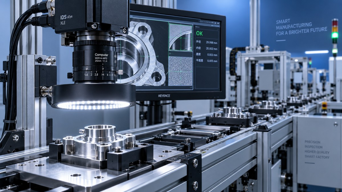
Many factory vision stations operate at medium distances because they allow room for lighting, guarding, and material handling while maintaining workable magnification. This range is often suitable for general presence/absence checks, label inspection, connector verification, seal inspection, robotic guidance, and moderate-tolerance dimensional work.
Here, lens selection is less about finding a theoretical maximum and more about balancing field coverage, aperture, and image uniformity. A lens should cover the sensor format with adequate corner performance at the chosen f-number. If the camera uses a larger sensor than the lens was designed to support, vignetting and reduced edge sharpness can quietly degrade detection at the perimeter of the image.
Medium-WD applications are also where a fixed focal length lens is frequently preferable to a varifocal option. A fixed focal length design generally offers more predictable geometry and better resistance to accidental adjustment. Varifocal lenses remain useful during feasibility work or when a station must support multiple product formats, but they should be mechanically locked and revalidated after adjustment.
Long working distance: control vibration, light, and perspective
Long-WD inspection is common where the camera must remain outside a process zone: hot parts, large fabricated assemblies, wide conveyors, aerospace structures, hazardous environments, or robot cells with limited access. The optical challenge is not simply “zooming in.” A longer focal length may recover the required field of view, but the system becomes more vulnerable to vibration and alignment drift. A small angular movement at the camera can translate into a meaningful object-plane shift.
Illumination deserves equal attention. At longer distances, reflected light returning to the lens may be limited, especially on dark, matte, or textured materials. Opening the aperture improves exposure but reduces depth of field and can expose weaker edge performance. Raising camera gain may preserve brightness while reducing signal-to-noise ratio. In other words, a long-distance optical decision is often constrained by the lighting budget.
For large parts with modest feature-resolution requirements, a wider field and lower magnification may be acceptable. When a large field must be measured precisely, conventional perspective optics may be the wrong tool. This is where telecentric imaging or a multi-camera architecture should enter the evaluation.
Choose Between Entocentric and Telecentric Optics Deliberately
Most standard lenses are entocentric: objects farther from the lens appear smaller, just as they do to the human eye. This perspective is acceptable—and often desirable—for general inspection, code reading, scene monitoring, and many defect-detection tasks. It becomes problematic when the inspection relies on accurate edge location, diameter measurement, or consistent apparent size while part height varies.
Telecentric lenses are designed to reduce magnification change over a specified depth range. They are particularly valuable for gauging stamped parts, measuring outer profiles, inspecting holes and pins, checking medical components, and evaluating features where perspective error would corrupt a result. Their benefits come with cost, size, illumination considerations, and finite usable field. They are not a universal upgrade.
A practical rule is to ask: Would a small change in part height alter the pass/fail result? If the answer is yes, quantify that risk before defaulting to a conventional lens. A calibrated entocentric lens can still support accurate measurement when object height is tightly controlled. But if height varies and the tolerance is narrow, telecentric machine vision optics may reduce both software compensation effort and inspection uncertainty.
Depth of Field Is a System Budget, Not an Aperture Setting
Depth of field (DOF) is frequently oversimplified as “close the aperture for more focus.” Stopping down does increase the range that appears acceptably sharp, but diffraction eventually reduces fine detail. The optimal f-number is therefore a compromise between DOF, diffraction, available light, exposure time, and lens performance.
For a moving production line, this balance becomes tighter. A smaller aperture may require a longer exposure, which can create motion blur. Strobe illumination can solve the exposure problem, but only if the light output, trigger timing, thermal behavior, and surface response are validated. In a static inspection cell, a smaller aperture may be entirely reasonable. In a high-speed web inspection application, it may be unusable.
Evaluate depth of field against the real height range of the inspected feature, not only the nominal part drawing. Include bowing, fixture variation, conveyor runout, robotic placement error, and lens focus drift due to vibration or temperature. If the system only passes when a sample is placed perfectly on a laboratory fixture, it has not yet demonstrated production readiness.
Distortion, MTF, and Sensor Matching: The Quiet Sources of Error
Lens specifications can look comparable until the application demands traceable results. Three areas deserve closer scrutiny.
Distortion affects geometric accuracy. Barrel or pincushion distortion can often be corrected in software, but the correction should be based on a proper calibration procedure at the actual working distance and focus setting. Calibration does not compensate for every issue: poor corner sharpness and unstable mechanics can still limit repeatability.
MTF indicates how well contrast is transferred at different spatial frequencies. For inspection, the relevant question is not whether a lens has a strong central MTF curve, but whether its performance remains sufficient across the entire sensor and at the selected aperture. A camera with smaller pixels can reveal optical limitations that were invisible with an older, lower-resolution sensor.
Sensor matching includes image-circle coverage, pixel size, mount compatibility, and chief-ray angle considerations. Do not assume a lens advertised for a certain megapixel count is automatically suitable. “Megapixel” labels do not define performance at your sensor size, wavelength, aperture, or working distance. Review sensor format first, then evaluate image quality at the required field corners.
Lighting Changes What the Lens Needs to See
Optics cannot create defect contrast that illumination fails to produce. A scratch may disappear under diffuse frontal light yet become obvious with low-angle dark-field illumination. A printed code may need coaxial light to suppress glare from a flat reflective substrate. Backlighting can provide exceptionally clean silhouettes for edge measurement, but it is not useful for every surface defect.
Lighting geometry also influences aperture choice. A well-designed strobed light can support a smaller aperture and stronger depth of field without unacceptable motion blur. Conversely, an underpowered lighting arrangement may force a wide aperture, leaving the inspection vulnerable to focus variation. During feasibility testing, lock the lens decision and the illumination concept together.
For multispectral, ultraviolet, infrared, or near-infrared inspection, confirm lens transmission and focus behavior at the operating wavelength. A lens optimized for visible light may shift focus or lose contrast outside that band. This is particularly relevant for ink inspection, moisture-related contrast, material sorting, and edge AI systems that use non-visible illumination to isolate a defect signature.
A Selection Sequence That Holds Up in Technical Review
- Define the real FOV, working-distance window, part-height variation, and smallest relevant feature.
- Calculate the required object-side pixel scale and select a sensor resolution with inspection margin.
- Identify candidate focal lengths using the intended sensor format and physical mounting envelope.
- Decide whether perspective variation is acceptable; assess telecentric optics when measurement sensitivity or height variation requires it.
- Set a preliminary aperture based on depth of field, then validate diffraction and exposure requirements.
- Review distortion, MTF, image-circle coverage, and close-focus performance at the actual operating condition.
- Test with representative parts, realistic lighting, expected motion, and the full range of positional variation.
- Document calibration method, focus-lock method, acceptable working-distance tolerance, and revalidation triggers.
This sequence may feel slower than selecting from a familiar lens series, but it reduces the chance of moving uncertainty downstream into image processing. Algorithms can classify, segment, and measure; they cannot reliably restore optical information that was never captured.
Common Selection Errors to Catch Before Release
The most expensive optics mistake is choosing based on a single “good image.” A sharp central image of one ideal sample says little about corner performance, height variation, production lighting, or throughput.
Another frequent error is designing around nominal working distance without accounting for its tolerance. If a lens is focused at 300 mm but the production system varies from 285 mm to 315 mm, validate the complete range. The same principle applies to thermal expansion, changeover tooling, and camera replacement.
Finally, avoid treating calibration as a cure-all. Calibration is essential for many measurement systems, yet it must be supported by stable optics and mechanics. If focus, aperture, lens position, or working distance changes, the calibration may no longer represent the inspection geometry.
Make the Optical Decision Traceable
For technical evaluators, the final lens choice should be defensible in a design review and repeatable across deployments. Record the camera model, sensor dimensions, lens model, focal length, aperture, working distance, field of view, lighting geometry, calibration target, and verified inspection result. Include the limits: maximum allowed part-height variation, minimum contrast condition, and any defects that remain below reliable detection threshold.
This data-first approach reflects a simple engineering truth: machine vision optics should be selected against measurable inspection requirements, not visual preference or catalogue language. When working distance, magnification, depth of field, distortion, and illumination are evaluated as a connected system, the result is not merely a clearer image. It is a more credible basis for automated decisions on the factory floor.
Search News
Hot Articles
- Carbon Fiber StructuresHow to Specify Aerospace Carbon Fiber Assemblies for Lightweight, Load-Bearing PartsJul 11, 2026
- Machine VisionXiaomi, Alibaba DAMO Academy Drive Open-Source Robotics Model Ecosystem, Lowering Algorithm Development Barriers for Overseas SMEs Adopting Chinese Robotics SolutionsMar 30, 2026
- Cobots & ArmsShanxi 'AI+' Conference Showcases Embodied Intelligence with Multinational Buyer Engagement: Key Industry ImplicationsMar 30, 2026
Popular Tags
Recommended News
 Jul 11, 2026How to Specify Aerospace Carbon Fiber Assemblies for Lightweight, Load-Bearing PartsAerospace carbon fiber assemblies: learn how to specify laminate design, load data, joining methods, and inspection controls for lighter, reliable load-bearing aerospace parts.Elena Rostova (UAV Systems Researcher)
 Mar 30, 2026Xiaomi, Alibaba DAMO Academy Drive Open-Source Robotics Model Ecosystem, Lowering Algorithm Development Barriers for Overseas SMEs Adopting Chinese Robotics SolutionsXiaomi & Alibaba DAMO Academy's open-source robotics models lower algorithm barriers for global SMEs. Boost efficiency in manufacturing, logistics & smart retail with ROS 2 compatible solutions.TSV Data Lab
 Mar 30, 2026Shanxi 'AI+' Conference Showcases Embodied Intelligence with Multinational Buyer Engagement: Key Industry ImplicationsShanxi 'AI+' Conference highlights embodied intelligence with Tesla, Ubtech & Jiantao showcasing multimodal robotics. 40+ global buyers validated tech on-site, creating new B2B channels for industrial automation & AI solutions.Chen Wei (Automation Lead Engineer)
 Mar 30, 2026Zhongguancun Unveils 6G Integrated Sensing-Computing-Intelligence Platform to Empower Embodied Robots for Global Industrial ApplicationsZhongguancun's new 6G platform revolutionizes industrial robotics with <10ms latency, empowering global automotive, logistics & port automation. Discover how this tech boosts China's smart manufacturing exports.TSV Data Lab
 Mar 30, 2026Mech-Mind Tianjin Embodied Intelligence R&D and Production Base Goes Live, Cutting Delivery Time by 20%–30% for Global Customized AMR+Vision SolutionsMech-Mind's Tianjin AMR+Vision production base cuts delivery time by 20%-30% for欧美 & Latin American markets. Discover how this PLd-certified facility accelerates customized robotics solutions for smart manufacturing and logistics.Chen Wei (Automation Lead Engineer)
 Mar 30, 2026Boao Forum Reveals 'Co-evolution of Big and Small Brains' Trend in Humanoid Robots, China's Embodied Intelligence Accelerates Adaptation to Overseas Manufacturing Service ScenariosDiscover how China's humanoid robots, featuring 'Co-evolution of Big and Small Brains,' are revolutionizing global manufacturing. Learn about Embodied Tian Gong 3.0's ISO compliance and overseas deployment at Boao Forum 2026.Chen Wei (Automation Lead Engineer)
 Mar 30, 2026China Railway Industrial Secures Patent for Embodied Robotics in Material Handling, Boosting High-Precision Delivery Capabilities for Overseas Infrastructure and Manufacturing ProjectsChina Railway Industrial's new patent for embodied robotics in material handling boosts high-precision delivery for global infrastructure & manufacturing. Discover how this innovation enhances logistics accuracy in automotive, rail transit & EPC projects.Chen Wei (Automation Lead Engineer)
 Sep 24, 2026How to Select Machine Vision Optics for Accurate Inspection at Different Working DistancesMachine vision optics selection guide for accurate inspection at every working distance. Compare FOV, pixel scale, DOF, distortion, lighting, and telecentric options.TSV Data Lab
 Sep 23, 2026How to Evaluate a Machine Vision System Integrator for High-Speed Inspection LinesChoose a machine vision system integrator with proven expertise in high-speed inspection, reliable reject timing, robust optics, and measurable acceptance criteria.TSV Data Lab
 Sep 24, 2026When does Industrial IoT make smart manufacturing easier to scale?Smart manufacturing Industrial IoT scales when trusted data, interoperable systems, and secure workflows turn connected assets into measurable gains.TSV Data Lab
 Sep 23, 2026What drives ultra-precision machining cost at 1-micron tolerance?Ultra precision machining cost per part at 1 micron tolerance depends on process, material, metrology, and yield. Learn how to compare quotes confidently.Dr. Marcus Vance
 Sep 22, 2026Drone Engine-T550CC Applications: Build the UAV Power System Around the MissionAn application guide for Drone Engine-T550CC integration, covering payload planning, airframe matching, cooling, fuel, vibration, test procedures, documentation, and service preparation.Elena Rostova (UAV Systems Researcher)
 Sep 22, 2026How to Evaluate Industrial Edge Computing Vendors for Factory DeploymentIndustrial edge computing vendor evaluation guide for factories: compare latency, protocol fit, reliability, security, and lifecycle support before deployment.TSV Data Lab
 Sep 21, 2026Drone Payload Integration: Matching Power, Data, and Center of Gravity for Reliable FlightsDrone payload integration made practical: balance power, data, center of gravity, and endurance to build safer, more reliable mission-ready flights.Elena Rostova (UAV Systems Researcher)
 Sep 20, 2026Autonomous Navigation Pricing: Cost Drivers and Budget Benchmarks for AMR ProjectsAutonomous navigation price explained: compare AMR cost drivers, software, sensors, integration, safety, and lifecycle budgets to build a scalable project plan.Chen Wei (Automation Lead Engineer)
 Sep 19, 2026How to Scope Automation Integration Services for Multi-System Factory ProjectsAutomation integration services: learn how to scope multi-system factory projects with clear workflows, interface contracts, safety boundaries, and acceptance criteria.Victor Lin (Chief Software Architect)
 Sep 18, 2026Selecting UAV Aerospace Structural Parts for Strength, Weight, and Fatigue LifeUAV aerospace structural parts guide: compare strength, weight, stiffness, fatigue life, joints, and traceability to select reliable flight-ready components.Elena Rostova (UAV Systems Researcher)
 Sep 17, 2026Selecting Commercial Drone Payloads for European Inspection ProjectsCommercial drone payloads Europe: learn how to select RGB, thermal and LiDAR systems for compliant, reliable inspection data and better project outcomes.Elena Rostova (UAV Systems Researcher)
 Sep 16, 2026Machining Tolerance Validation: How to Verify Critical Dimensions Before Production ReleaseMachining tolerance analysis validation: verify critical dimensions, measurement systems, process capability, and tolerance stacks before production release.Dr. Marcus Vance
 Sep 15, 2026AGV Tape Guidance vs Laser Navigation: Which Fits Your Warehouse Layout?AGV tape guidance comparison: discover how tape and laser navigation fit changing warehouse layouts, docking needs, floor conditions, maintenance, and route flexibility.Chen Wei (Automation Lead Engineer)
 Sep 14, 2026How Point Cloud Analytics Improves Asset Inspection Workflows Across GCC ProjectsPoint cloud analytics GCC helps project leaders improve asset inspections with accurate change detection, safer workflows, and faster maintenance decisions.TSV Data Lab
 Sep 13, 2026How Aerospace Manufacturers Can Build a Digital Thread From Design to Certified ProductionDigital manufacturing for aerospace: learn how to build a traceable digital thread from design through certified production, supplier control, and audit-ready compliance.Victor Lin (Chief Software Architect)
 Sep 12, 2026How to Select a Thermal Sensor for Mapping Drones in Surveying ProjectsMapping drone thermal sensor selection made simple: compare GSD, radiometric data, NETD, calibration, and workflow fit for accurate, survey-ready thermal maps.Elena Rostova (UAV Systems Researcher)
 Sep 11, 2026Integrating Photogrammetry Workflows into Digital Twin Projects Without Data BottlenecksPhotogrammetry workflow integration for digital twins: learn how to streamline capture, validation, versioning, and delivery to prevent data bottlenecks.Victor Lin (Chief Software Architect)