How to Select Wall-Mount Edge Devices for Space-Constrained Factory Networks
Publication Date
author
A wall-mounted edge device is not selected successfully when it fits inside a cabinet or occupies an unused section of wall. It is selected successfully when its compute load, heat dissipation path, cable geometry, service access, power behavior, and network interfaces remain acceptable after the enclosure door is closed and the production area is operating normally.
That distinction matters in space-constrained factory networks. Compact installations often place edge hardware beside machine control panels, in shallow electrical cabinets, under conveyor frames, or on narrow structural columns. Those locations reduce cable runs and latency, but they also concentrate risks that are easy to miss in a datasheet comparison: blocked airflow, excessive connector bend radius, unmanaged heat from adjacent drives, inaccessible reset controls, ground-potential differences, and insufficient clearance for replacing a failed unit.
Wall mount edge devices should therefore be evaluated as part of a physical and electrical system rather than as isolated computing appliances. A device with a higher processor specification can be the weaker choice if the intended mounting location cannot remove its heat, support its cable load, or provide the network redundancy required by the application.
Start with the actual edge workload, not the processor family
“Edge processing” can describe very different functions. A gateway collecting status data from PLCs and publishing it to an MES has a substantially different resource profile from a unit running machine-vision inference, aggregating high-frequency sensor streams, executing local control logic, or buffering data during a WAN outage. Selecting by CPU generation, core count, or an advertised AI performance figure alone obscures the more important question: what must be processed locally, at what rate, and what happens when the load peaks?
A useful workload definition should identify:
- the number and type of connected assets;
- protocols in use, such as OPC UA, Modbus TCP, EtherNet/IP, PROFINET, MQTT, or vendor-specific interfaces;
- data update intervals, message sizes, and expected concurrent connections;
- local services, including protocol conversion, database writes, containerized applications, dashboards, rules engines, and security agents;
- retention requirements during upstream network or cloud interruptions; and
- maximum acceptable latency for each function.
These requirements should be separated by criticality. A process visualization update that arrives a second late may be harmless; a local interlock, vision reject decision, or motion-related data exchange may not be. Where the edge device is involved in a control-adjacent function, deterministic behavior and failure handling deserve more scrutiny than average processor utilization.
CPU load should be assessed under realistic simultaneous conditions rather than in a nominal steady state. This includes startup surges, database maintenance, certificate renewal, log rotation, retransmissions after a network interruption, and model inference at the maximum expected image or sensor rate. Memory headroom is equally important. Systems that operate near RAM limits can become unstable due to swapping, container restarts, or delayed application responses long before CPU utilization appears excessive.
For AI-enabled workloads, verify the complete execution path. A quoted TOPS value does not establish useful performance unless the accelerator supports the intended framework, model format, precision, operator set, runtime version, and input pipeline. Camera decoding, image preprocessing, post-processing, storage writes, and network transfers may consume more time than inference itself. The relevant result is end-to-end decision latency at the required throughput, not the accelerator’s theoretical arithmetic capability.
The wall location defines the thermal design
Thermal performance is often the decisive constraint in compact deployments. Fanless industrial computers are attractive because they eliminate fan maintenance and reduce the ingress path for dust. Their reliability, however, depends on transferring heat from internal components through the chassis and into the surrounding air. A fanless device mounted in a shallow, unventilated cabinet can retain heat more effectively than it dissipates it.
The published operating-temperature range must be read carefully. It may apply only to a specified processor configuration, storage type, power input, orientation, or airflow condition. It may also reflect ambient air around the unit, not the temperature inside a cabinet positioned next to variable-frequency drives, servo amplifiers, transformers, or pneumatic equipment exposed to solar gain. Cabinet air temperature can differ materially from the general room temperature.
Installation drawings should be reviewed for required clearance above, below, and beside the enclosure. Cooling fins need access to moving air, and a device mounted flat against an insulating surface may not perform as assumed. Orientation matters when heat sinks are designed for natural convection. A chassis approved for vertical mounting should not automatically be installed horizontally beneath a machine frame merely because the mounting holes align.
Thermal evaluation should also account for the selected expansion hardware. NVMe storage, PoE ports, cellular modules, GPU or AI accelerators, and high-speed network adapters can add heat beyond the base configuration. A configuration that is stable with a low-power processor and one Ethernet interface may throttle or shut down with additional I/O modules under sustained load.
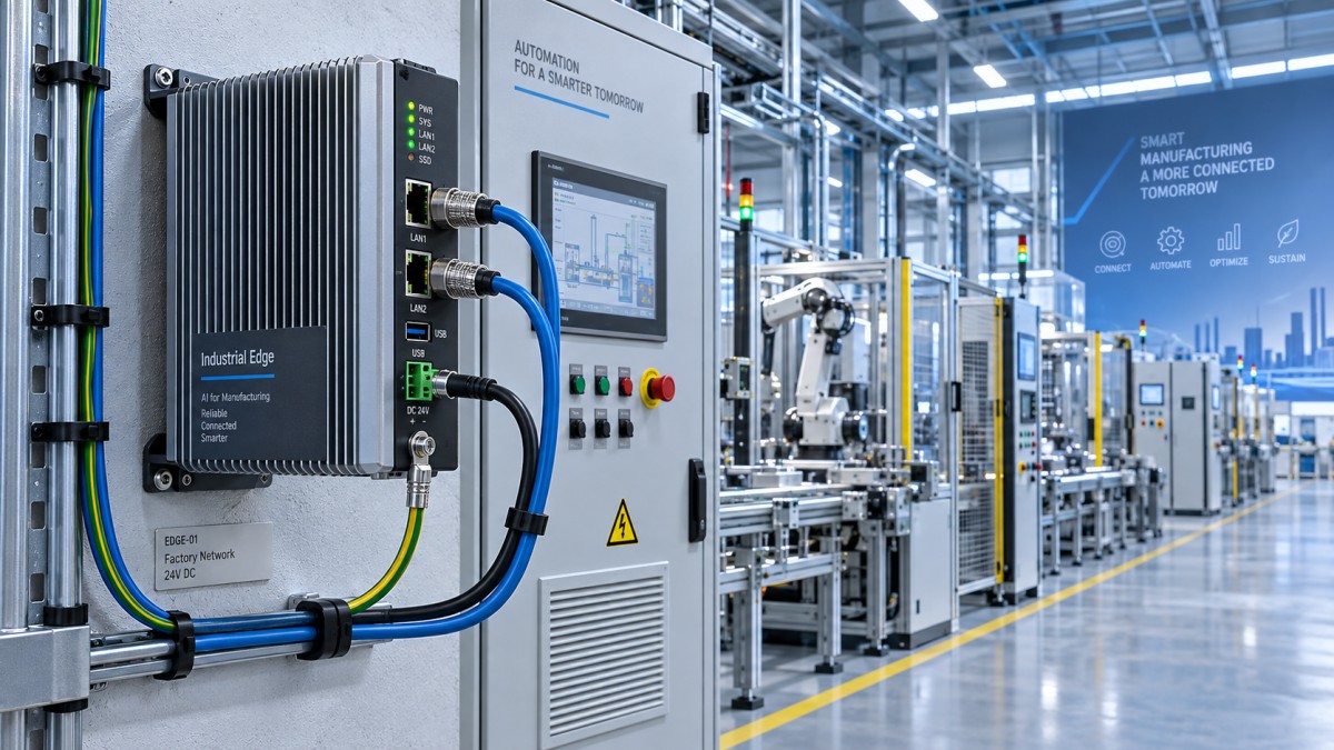
A practical acceptance condition is more useful than a room-temperature bench test: run the intended application at its maximum expected load in the final enclosure, with neighboring equipment energized, and observe temperature, clock throttling, error logs, link stability, and application response over a sufficient operating cycle. The aim is not simply to confirm that the device remains powered on. It is to confirm that it retains the processing margin required for normal production events.
Ingress protection and thermal management must be evaluated together
IP ratings answer a specific question: how well an enclosure resists access, solid objects, and water under defined test conditions. They do not establish suitability for every industrial environment. A high-IP enclosure can be appropriate near washdown exposure or airborne contaminants, but its sealing approach may constrain heat removal. Conversely, a device with an exposed finned chassis may dissipate heat well while being unsuitable for areas with conductive dust, oil mist, fibers, or direct washdown.
Selection should begin with the actual exposure mechanism. Fine metal dust, flour dust, coolant aerosol, chemical vapor, intermittent hose-down, condensation, and outdoor humidity impose different demands. A device inside a larger protected control enclosure may not need the same IP rating as a unit mounted directly on a production cell. But placing a lower-rated device in a cabinet shifts the evaluation to the cabinet: its gasket condition, cable entries, ventilation design, condensation control, and maintenance discipline become part of the protection strategy.
Condensation deserves particular attention where equipment is moved between temperature zones, installed in humid areas, or subject to frequent cabinet cooling cycles. Water ingress is not the only concern. Moisture can corrode connectors, reduce insulation resistance, and create intermittent faults that are difficult to trace. Where the environmental risk is significant, the design should consider enclosure breathing, anti-condensation heating, cable-gland selection, and the temperature range of the complete installed assembly.
Mechanical fit includes access, cable routing, and vibration
Wall mounting is often treated as a bracket specification. In practice, the critical question is whether the complete installed device can be cabled, serviced, and replaced without disturbing surrounding systems.
Measure the device depth with connectors installed, not chassis depth alone. Industrial Ethernet plugs, M12 connectors, fiber transceivers, USB devices, antenna leads, and power connectors can extend well beyond the enclosure. Copper Ethernet cables also require bend radius and strain relief. Tight routing may exert continuous force on ports, make latch release impossible, or place a connector directly against a cabinet door.
Service access is commonly lost when a compact unit is mounted in the final available space. Confirm access to power terminals, grounding points, storage bays, SIM slots, reset controls, diagnostic LEDs, and mounting screws. If replacement requires removing a cable duct, disconnecting a neighboring controller, or opening a live high-voltage compartment, the apparent space saving becomes a lifecycle liability.
Mounting hardware should match both the wall material and the device mass after optional modules and cabling are added. Sheet-metal panels may need reinforcement. Machine frames can transmit vibration that is absent from the device’s basic mounting test. For locations near presses, conveyors, mobile equipment, or rotating machinery, verify the vendor’s vibration and shock specifications against the site condition and ensure the selected SSD, memory, and connector system are appropriate. A standard office-style connector arrangement may be less robust than locking industrial connectors in a high-vibration location.
Power architecture is a reliability decision, not an accessory choice
Industrial edge systems are frequently powered from 24 VDC supplies, but the nominal input voltage is only one part of the requirement. Evaluate the permissible voltage range, startup inrush current, reverse-polarity protection, transient tolerance, isolation characteristics, and behavior during brief interruptions. A supply that is adequate in continuous-state calculations may still dip during startup or when a nearby actuator changes state.
If the device processes data that must not be lost during a short power event, define the expected behavior explicitly. Options include a UPS, DC hold-up module, controlled shutdown software, redundant power inputs, or storage designed to tolerate abrupt loss of power. These approaches solve different problems. Redundant inputs improve resilience against a single supply path failure, but they do not necessarily provide runtime during a site-wide outage. A UPS provides time, but only if the load and battery system are correctly sized and maintained.
Storage architecture needs similar scrutiny. Local buffering can protect production data during an uplink outage, but retention capacity depends on real write volume, not an estimated average. Continuous databases, video frames, event logs, and sensor histories can produce sustained writes that affect both capacity and SSD endurance. Check the storage medium’s endurance rating, expected write amplification, replacement method, and whether the operating system and application can recover cleanly after an unplanned shutdown.
Grounding and shielding should be included in the installation review. Edge devices often bridge networks and power domains that originate from different panels or machine cells. Poor bonding, unsuitable shield termination, or unmanaged potential differences can appear as intermittent Ethernet faults, serial communication errors, or unexplained resets. The physical installation must follow the manufacturer’s grounding instructions and the site’s electrical design rules; neither should be inferred from connector appearance.
Network compatibility is more than counting Ethernet ports
A wall-mounted edge appliance may need to act as a data collector, protocol gateway, local application host, firewall, router, managed switch endpoint, or all of these simultaneously. The required network behavior should be stated before selecting ports.
Two Ethernet interfaces do not automatically provide network separation, redundancy, or switching capability. Determine whether ports are independent NICs, internally switched, bypass-enabled, or subject to shared bandwidth. Confirm support for required link speeds, VLAN tagging, multicast handling, quality-of-service behavior, time synchronization, and industrial protocol requirements. If the device must communicate across an OT network and an IT network, its segmentation role needs to be designed deliberately rather than created by plugging cables into separate ports.
Time-sensitive applications require particular care. A device can receive timestamps without being an appropriate time source. Where event ordering, synchronized sensing, or motion-adjacent analytics matter, assess support for the site’s timing architecture, including NTP, PTP, hardware timestamping where required, and the accuracy expected after network delay and software processing are considered. “Low latency” is not a universal property; it depends on traffic conditions, operating-system scheduling, protocol stack behavior, and the entire network path.
Cellular or Wi-Fi connectivity can support isolated assets or temporary deployment, but it should not be treated as equivalent to a controlled wired industrial network. Antenna placement, metal enclosures, radio interference, SIM lifecycle management, carrier availability, and remote-access security all affect operational suitability. An internal modem without a viable RF path is not a connectivity strategy.
Do not confuse rugged hardware with manageable infrastructure
Long service life depends on software and support conditions as much as on enclosure construction. Confirm the operating system version, patching method, application deployment model, remote-management capability, BIOS or firmware update process, and recovery procedure. A device installed in a difficult-to-access location should support a controlled way to diagnose failures without requiring a keyboard, display, or physical visit for every incident.
Lifecycle evaluation should identify which components are field-replaceable and which are effectively fixed. Memory, SSDs, wireless modules, power supplies, and removable storage each have different failure and replacement implications. Also verify the availability window for the exact configured model, not merely the product family. Industrial projects may require identical replacements years after the first installation, and a revised chipset, different network controller, or changed operating-system support status can introduce requalification work.
Cybersecurity requirements should be translated into operational controls: secure boot where applicable, TPM availability, encrypted storage requirements, account management, certificate handling, disabled unused ports, firewall policy, remote-access method, and vulnerability patch ownership. A compact edge device often becomes a bridge between operational systems and higher-level services. That role makes configuration governance more important, not less.
A defensible selection ends with an installed-state verification
The most reliable specification for wall mount edge devices combines device parameters with location-specific acceptance criteria. It should state the workload, maximum ambient condition at the installation point, enclosure and mounting orientation, required clearance, power source and interruption behavior, connector and cable routing constraints, network function, software baseline, and service-access requirements.
Before standardizing a design, verify the complete configured unit in its intended physical arrangement. Confirm sustained workload performance, thermal margin, cable fit, port accessibility, power recovery, network reconnection, local data retention, and remote management. This is where a device that appears suitable in a catalogue either proves compatible with the factory network or exposes the compromises that must be corrected before deployment.
In constrained installations, the best choice is rarely the smallest chassis or the highest headline performance. It is the unit whose compute capacity, environmental limits, interfaces, and lifecycle controls remain valid after the realities of the wall, cabinet, cables, power system, and production network are taken into account.
Search News
Hot Articles
- Carbon Fiber StructuresHow to Specify Aerospace Carbon Fiber Assemblies for Lightweight, Load-Bearing PartsJul 11, 2026
- Machine VisionXiaomi, Alibaba DAMO Academy Drive Open-Source Robotics Model Ecosystem, Lowering Algorithm Development Barriers for Overseas SMEs Adopting Chinese Robotics SolutionsMar 30, 2026
- Cobots & ArmsShanxi 'AI+' Conference Showcases Embodied Intelligence with Multinational Buyer Engagement: Key Industry ImplicationsMar 30, 2026
Popular Tags
Recommended News
 Jul 11, 2026How to Specify Aerospace Carbon Fiber Assemblies for Lightweight, Load-Bearing PartsAerospace carbon fiber assemblies: learn how to specify laminate design, load data, joining methods, and inspection controls for lighter, reliable load-bearing aerospace parts.Elena Rostova (UAV Systems Researcher)
 Mar 30, 2026Xiaomi, Alibaba DAMO Academy Drive Open-Source Robotics Model Ecosystem, Lowering Algorithm Development Barriers for Overseas SMEs Adopting Chinese Robotics SolutionsXiaomi & Alibaba DAMO Academy's open-source robotics models lower algorithm barriers for global SMEs. Boost efficiency in manufacturing, logistics & smart retail with ROS 2 compatible solutions.TSV Data Lab
 Mar 30, 2026Shanxi 'AI+' Conference Showcases Embodied Intelligence with Multinational Buyer Engagement: Key Industry ImplicationsShanxi 'AI+' Conference highlights embodied intelligence with Tesla, Ubtech & Jiantao showcasing multimodal robotics. 40+ global buyers validated tech on-site, creating new B2B channels for industrial automation & AI solutions.Chen Wei (Automation Lead Engineer)
 Mar 30, 2026Zhongguancun Unveils 6G Integrated Sensing-Computing-Intelligence Platform to Empower Embodied Robots for Global Industrial ApplicationsZhongguancun's new 6G platform revolutionizes industrial robotics with <10ms latency, empowering global automotive, logistics & port automation. Discover how this tech boosts China's smart manufacturing exports.TSV Data Lab
 Mar 30, 2026Mech-Mind Tianjin Embodied Intelligence R&D and Production Base Goes Live, Cutting Delivery Time by 20%–30% for Global Customized AMR+Vision SolutionsMech-Mind's Tianjin AMR+Vision production base cuts delivery time by 20%-30% for欧美 & Latin American markets. Discover how this PLd-certified facility accelerates customized robotics solutions for smart manufacturing and logistics.Chen Wei (Automation Lead Engineer)
 Mar 30, 2026Boao Forum Reveals 'Co-evolution of Big and Small Brains' Trend in Humanoid Robots, China's Embodied Intelligence Accelerates Adaptation to Overseas Manufacturing Service ScenariosDiscover how China's humanoid robots, featuring 'Co-evolution of Big and Small Brains,' are revolutionizing global manufacturing. Learn about Embodied Tian Gong 3.0's ISO compliance and overseas deployment at Boao Forum 2026.Chen Wei (Automation Lead Engineer)
 Mar 30, 2026China Railway Industrial Secures Patent for Embodied Robotics in Material Handling, Boosting High-Precision Delivery Capabilities for Overseas Infrastructure and Manufacturing ProjectsChina Railway Industrial's new patent for embodied robotics in material handling boosts high-precision delivery for global infrastructure & manufacturing. Discover how this innovation enhances logistics accuracy in automotive, rail transit & EPC projects.Chen Wei (Automation Lead Engineer)
 Sep 27, 2026How to Select Wall-Mount Edge Devices for Space-Constrained Factory NetworksWall mount edge devices for space-constrained factories: evaluate workload, thermal design, power resilience, cable access, and network reliability for smarter deployments.TSV Data Lab
 Sep 26, 2026Machining Tolerance Analysis: How to Set Limits That Meet Function and Cost TargetsMachining tolerance analysis: learn how to set functional limits, control tolerance stacks, reduce inspection risk, and balance precision with production cost.Dr. Marcus Vance
 Sep 25, 2026How to Evaluate an Industrial Infrastructure Data Platform for Multi-Site OperationsIndustrial infrastructure data platform evaluation guide for multi-site operations: compare data quality, edge resilience, interoperability, governance, and scalable proof-of-value criteria.Victor Lin (Chief Software Architect)
 Sep 24, 2026How to Select Machine Vision Optics for Accurate Inspection at Different Working DistancesMachine vision optics selection guide for accurate inspection at every working distance. Compare FOV, pixel scale, DOF, distortion, lighting, and telecentric options.TSV Data Lab
 Sep 23, 2026How to Evaluate a Machine Vision System Integrator for High-Speed Inspection LinesChoose a machine vision system integrator with proven expertise in high-speed inspection, reliable reject timing, robust optics, and measurable acceptance criteria.TSV Data Lab
 Sep 26, 2026What to define before starting SCADA integration planningSCADA integration planning starts with clear scope, control boundaries, data models, cybersecurity, and testing. Discover the definitions that reduce risk and costly rework.Victor Lin (Chief Software Architect)
 Sep 25, 2026How a smart factory with Industrial IoT reduces production blind spotsDiscover how a smart factory with Industrial IoT turns real-time machine, quality, and workflow data into actionable insights that reduce production blind spots and delivery risks.Victor Lin (Chief Software Architect)
 Sep 24, 2026When does Industrial IoT make smart manufacturing easier to scale?Smart manufacturing Industrial IoT scales when trusted data, interoperable systems, and secure workflows turn connected assets into measurable gains.TSV Data Lab
 Sep 23, 2026What drives ultra-precision machining cost at 1-micron tolerance?Ultra precision machining cost per part at 1 micron tolerance depends on process, material, metrology, and yield. Learn how to compare quotes confidently.Dr. Marcus Vance
 Sep 22, 2026Drone Engine-T550CC Applications: Build the UAV Power System Around the MissionAn application guide for Drone Engine-T550CC integration, covering payload planning, airframe matching, cooling, fuel, vibration, test procedures, documentation, and service preparation.Elena Rostova (UAV Systems Researcher)
 Sep 22, 2026How to Evaluate Industrial Edge Computing Vendors for Factory DeploymentIndustrial edge computing vendor evaluation guide for factories: compare latency, protocol fit, reliability, security, and lifecycle support before deployment.TSV Data Lab
 Sep 21, 2026Drone Payload Integration: Matching Power, Data, and Center of Gravity for Reliable FlightsDrone payload integration made practical: balance power, data, center of gravity, and endurance to build safer, more reliable mission-ready flights.Elena Rostova (UAV Systems Researcher)
 Sep 20, 2026Autonomous Navigation Pricing: Cost Drivers and Budget Benchmarks for AMR ProjectsAutonomous navigation price explained: compare AMR cost drivers, software, sensors, integration, safety, and lifecycle budgets to build a scalable project plan.Chen Wei (Automation Lead Engineer)
 Sep 19, 2026How to Scope Automation Integration Services for Multi-System Factory ProjectsAutomation integration services: learn how to scope multi-system factory projects with clear workflows, interface contracts, safety boundaries, and acceptance criteria.Victor Lin (Chief Software Architect)
 Sep 18, 2026Selecting UAV Aerospace Structural Parts for Strength, Weight, and Fatigue LifeUAV aerospace structural parts guide: compare strength, weight, stiffness, fatigue life, joints, and traceability to select reliable flight-ready components.Elena Rostova (UAV Systems Researcher)
 Sep 17, 2026Selecting Commercial Drone Payloads for European Inspection ProjectsCommercial drone payloads Europe: learn how to select RGB, thermal and LiDAR systems for compliant, reliable inspection data and better project outcomes.Elena Rostova (UAV Systems Researcher)
 Sep 16, 2026Machining Tolerance Validation: How to Verify Critical Dimensions Before Production ReleaseMachining tolerance analysis validation: verify critical dimensions, measurement systems, process capability, and tolerance stacks before production release.Dr. Marcus Vance