Spindle Runout Measurement in Germany: DIN Standards, Methods, and Acceptance Limits
Publication Date
author
Spindle Runout Measurement in Germany: DIN Standards, Methods, and Acceptance Limits
Spindle runout measurement in Germany is not a cosmetic maintenance check. In a precision machining environment, it is evidence: evidence of spindle condition, interface quality, machine capability, and, in some cases, a developing safety risk. A spindle that appears acceptable during an unloaded indicator test can still create poor bore geometry, shortened tool life, unstable cutting forces, or unexplained variation once it reaches production speed and temperature.
For quality and safety teams, the difficult part is rarely placing a dial indicator against a test bar. The difficult part is deciding what exactly has been measured, which standard is relevant, whether the result is repeatable, and whether the acceptance limit reflects the actual machining task rather than a convenient shop-floor rule.
German manufacturing practice tends to treat this distinction seriously. DIN-adopted standards, machine acceptance records, tool-interface specifications, and internal control plans often work together. They should not be treated as interchangeable. A tolerance stated for a toolholder taper, for example, is not automatically the permissible runout of the complete rotating spindle assembly.
What runout actually means on a machine tool
Runout is commonly described as the variation observed while a rotating component turns around its intended axis. That description is useful, but incomplete. In practice, a spindle measurement may include radial movement at the spindle nose, movement of a taper test mandrel, runout at the toolholder gauge line, or eccentricity at the cutting edge. Each location answers a different question.
A quality record should therefore state whether the reported value is total indicator reading (TIR), radial runout, axial runout, or another defined characteristic. TIR is widely used on the shop floor, but it is not a universal substitute for a geometrically defined tolerance. If an internal specification says “maximum runout 5 µm” without defining the measuring point, reference surface, spindle state, and reading convention, it leaves too much room for disagreement.
The source of apparent runout also matters. The indicator may be seeing spindle-bearing error, contamination in the taper, damage to the toolholder, a bent test mandrel, incorrect clamping, thermal displacement, or a combination of these. Replacing a spindle because a holder was not cleaned is expensive. Ignoring a deteriorating bearing because a single cold test looked acceptable can be worse.
The standards landscape: DIN is a framework, not one runout number
There is no single DIN acceptance limit that can responsibly be applied to every spindle, every machine type, and every production process. In Germany, the relevant basis is usually a combination of the machine manufacturer’s acceptance documentation, the purchase specification, the applicable DIN EN ISO test code, the spindle and interface design, and the tolerance demanded by the part.
For machine-tool geometric testing, DIN EN ISO 230-1, the German adoption of ISO 230-1, is a central reference. It addresses test conditions and geometric accuracy for machine tools operating under no-load or finishing conditions. It provides a disciplined approach to test setup, environmental considerations, instruments, and recording. The exact applicability depends on the machine configuration and the test item under review, so teams should work from the current controlled edition and the manufacturer’s specified procedure rather than relying on an old checklist.
For machining centres, the DIN EN ISO 10791 series may also be relevant. Its different parts cover test conditions, geometric tests, positioning, interpolation and machined test pieces for machining centres. Turning-machine acceptance may involve other machine-specific standards and manufacturer documents. Where the interface itself is under examination, standards such as DIN 69871 for steep-taper shanks, DIN 69893 for HSK interfaces, or ISO 7388-related taper interface requirements can become relevant. These define important interface geometry, but they do not eliminate the need to assess the assembled spindle-tool system.
DIN ISO 1101 is also often mentioned in discussions of runout because it defines geometrical tolerancing concepts, including run-out controls on engineering drawings. Its role is different: it helps specify a component feature relative to a datum. It is not, by itself, a machine-spindle acceptance protocol.
That distinction is worth preserving in audit files. A sound inspection plan identifies the governing document for the machine test, the document controlling the interface, and the drawing requirement for the finished component. Mixing them produces reports that look formal but are technically hard to defend.
A practical measurement sequence that avoids misleading results
A useful spindle runout measurement begins before the spindle rotates. Lockout and machine safety procedures must be followed where guards are opened, tools are handled, or manual rotation is used. The spindle nose and tool interface should be inspected under adequate light. Chips, dried coolant residue, light corrosion, pull-stud problems, fretting marks, and damage around contact faces can all produce an abnormal reading.
The test mandrel is not a generic accessory. It should match the spindle interface and be sufficiently straight, clean, and traceable for the tolerance being evaluated. A test bar with unknown condition simply transfers uncertainty into the result. For very tight requirements, the measuring instrument, mandrel, and setup should have calibration status appropriate to the decision being made.
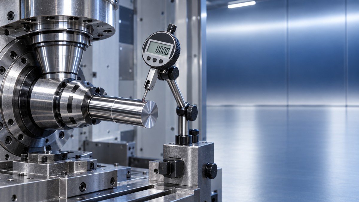
The usual static method uses a high-resolution dial test indicator or electronic probe mounted on a stable fixture. The spindle is rotated slowly by hand or in a controlled low-speed mode, depending on the machine and safe work instruction. Measurements are then taken at defined axial positions. A point close to the spindle nose is more diagnostic of the taper and bearing system; a point further along the mandrel magnifies angular error, but it is also more sensitive to the mandrel itself and fixture rigidity.
Axial runout is normally assessed on an appropriate face or reference surface. This is especially relevant where face-contact interfaces, precision boring operations, or tool seating are involved. However, the probe must contact the intended surface at a suitable angle. Poor probe geometry, excessive stylus force, or a flexible holder can create a result that appears precise while being fundamentally unreliable.
One static reading is not enough for a critical process. Repeat the clamp-and-measure cycle. If the value changes significantly after removing and reinstalling the same mandrel, investigate cleanliness, drawbar force, interface damage, and clamping consistency before drawing conclusions about bearings. For automated pallet systems or unattended production, this repeatability check is often more useful than a single best-case measurement.
Cold runout and operating runout are not the same condition
Static inspection is necessary, but it does not represent every production condition. At operating speed, thermal growth, preload changes, imbalance, cutting load, and toolholder dynamics can alter the effective rotating axis. A spindle that passes a low-speed test may still produce chatter or bore-size drift after a warm-up cycle.
For this reason, high-risk processes should separate at least three questions: Is the spindle geometrically acceptable when cold? Does its behavior remain stable at the intended speed after thermal stabilization? Does the complete tool assembly deliver the required result in a representative cut? These are related checks, not duplicates.
Dynamic assessment may require non-contact displacement sensors, vibration analysis, spindle diagnostics, a controlled warm-up routine, or a machined test piece. The method should be proportionate. A general-purpose machining centre producing non-critical brackets does not need the same evidence as a machine used for tight-tolerance aerospace features, medical-device components, high-speed micro-milling, or safety-relevant rotating parts.
How to set acceptance limits without inventing a universal threshold
The phrase “acceptable spindle runout” is often used as though it has one correct answer. It does not. A valid limit depends on the required feature tolerance, tool diameter, tool overhang, operation type, spindle speed, material, interface, and risk of failure. Reaming, finish boring, micro-drilling, grinding, and high-speed finishing are naturally more sensitive than many roughing operations.
The safest hierarchy is simple: start with the machine builder’s documented acceptance criteria and maintenance limits; then apply the purchase specification or customer requirement; then confirm that the selected limit supports the process capability required by the finished part. If these sources conflict, the conflict needs engineering resolution. It should not be settled by choosing the least restrictive number.
Internal warning and action limits can be valuable, particularly where trend data exists. A warning limit may trigger cleaning, remeasurement, or process observation. An action limit may require removal from critical work, service review, or further dynamic testing. These limits should be controlled as internal process criteria, not presented as DIN values unless the cited standard genuinely specifies them.
For safety managers, the concern extends beyond dimensional scrap. Excessive runout can increase uneven tooth loading, encourage tool breakage, worsen vibration, and add uncertainty to high-speed operations. It is rarely the only cause of an incident, but it can be part of a failure chain involving worn holders, incorrect balancing, inadequate retention, or poor preventive maintenance.
Documentation that remains credible during an audit or supplier dispute
A defensible report records more than a final micrometre value. It should identify the machine, spindle interface, machine state, warm-up condition, test mandrel, measurement locations, instrument identification, calibration status, rotation method, observed TIR or other stated metric, applicable acceptance criterion, and inspector. If ambient temperature or coolant condition is relevant to the requirement, capture that as well.
Photographs of the setup and a simple sketch of the probe positions can save considerable time later. They make it clear whether two measurements are actually comparable. This is particularly useful when equipment is evaluated across plants, suppliers, or service providers using different local habits.
A broader engineering benchmark should not confuse a polished claim with a measurement protocol. TechStat Vanguard’s approach—engineering truth through data—is useful here: the reported parameter only has value when its measurement basis is visible. “Low runout” is marketing language. A controlled result tied to a defined interface, method, instrument, temperature state, and acceptance source is engineering information.
The decision after a failed result
Do not immediately condemn the spindle. Start by cleaning the interface, checking the test mandrel, repeating the setup, and comparing measurements at more than one location. Test a known-good holder if practical. Review drawbar retention, taper condition, toolholder seating, and spindle operating history. A rising runout trend combined with vibration, heat, noise, poor finish, or repeated tool failures deserves faster escalation than an isolated measurement anomaly.
For spindle runout measurement in Germany, the strongest result is not the smallest number on an indicator. It is a measurement that can be reproduced, interpreted against the right DIN EN ISO and contractual references, and connected to a clear production decision. That is how a routine inspection becomes useful quality evidence rather than another number in a maintenance log.
Search News
Hot Articles
- Carbon Fiber StructuresHow to Specify Aerospace Carbon Fiber Assemblies for Lightweight, Load-Bearing PartsJul 11, 2026
- Machine VisionXiaomi, Alibaba DAMO Academy Drive Open-Source Robotics Model Ecosystem, Lowering Algorithm Development Barriers for Overseas SMEs Adopting Chinese Robotics SolutionsMar 30, 2026
- Cobots & ArmsShanxi 'AI+' Conference Showcases Embodied Intelligence with Multinational Buyer Engagement: Key Industry ImplicationsMar 30, 2026
Popular Tags
Recommended News
 Jul 11, 2026How to Specify Aerospace Carbon Fiber Assemblies for Lightweight, Load-Bearing PartsAerospace carbon fiber assemblies: learn how to specify laminate design, load data, joining methods, and inspection controls for lighter, reliable load-bearing aerospace parts.Elena Rostova (UAV Systems Researcher)
 Mar 30, 2026Xiaomi, Alibaba DAMO Academy Drive Open-Source Robotics Model Ecosystem, Lowering Algorithm Development Barriers for Overseas SMEs Adopting Chinese Robotics SolutionsXiaomi & Alibaba DAMO Academy's open-source robotics models lower algorithm barriers for global SMEs. Boost efficiency in manufacturing, logistics & smart retail with ROS 2 compatible solutions.TSV Data Lab
 Mar 30, 2026Shanxi 'AI+' Conference Showcases Embodied Intelligence with Multinational Buyer Engagement: Key Industry ImplicationsShanxi 'AI+' Conference highlights embodied intelligence with Tesla, Ubtech & Jiantao showcasing multimodal robotics. 40+ global buyers validated tech on-site, creating new B2B channels for industrial automation & AI solutions.Chen Wei (Automation Lead Engineer)
 Mar 30, 2026Zhongguancun Unveils 6G Integrated Sensing-Computing-Intelligence Platform to Empower Embodied Robots for Global Industrial ApplicationsZhongguancun's new 6G platform revolutionizes industrial robotics with <10ms latency, empowering global automotive, logistics & port automation. Discover how this tech boosts China's smart manufacturing exports.TSV Data Lab
 Mar 30, 2026Mech-Mind Tianjin Embodied Intelligence R&D and Production Base Goes Live, Cutting Delivery Time by 20%–30% for Global Customized AMR+Vision SolutionsMech-Mind's Tianjin AMR+Vision production base cuts delivery time by 20%-30% for欧美 & Latin American markets. Discover how this PLd-certified facility accelerates customized robotics solutions for smart manufacturing and logistics.Chen Wei (Automation Lead Engineer)
 Mar 30, 2026Boao Forum Reveals 'Co-evolution of Big and Small Brains' Trend in Humanoid Robots, China's Embodied Intelligence Accelerates Adaptation to Overseas Manufacturing Service ScenariosDiscover how China's humanoid robots, featuring 'Co-evolution of Big and Small Brains,' are revolutionizing global manufacturing. Learn about Embodied Tian Gong 3.0's ISO compliance and overseas deployment at Boao Forum 2026.Chen Wei (Automation Lead Engineer)
 Mar 30, 2026China Railway Industrial Secures Patent for Embodied Robotics in Material Handling, Boosting High-Precision Delivery Capabilities for Overseas Infrastructure and Manufacturing ProjectsChina Railway Industrial's new patent for embodied robotics in material handling boosts high-precision delivery for global infrastructure & manufacturing. Discover how this innovation enhances logistics accuracy in automotive, rail transit & EPC projects.Chen Wei (Automation Lead Engineer)
 Sep 28, 2026Spindle Runout Measurement in Germany: DIN Standards, Methods, and Acceptance LimitsSpindle runout measurement Germany: explore DIN standards, proven methods, acceptance limits, and audit-ready practices for reliable machining quality.Dr. Marcus Vance
 Sep 27, 2026How to Select Wall-Mount Edge Devices for Space-Constrained Factory NetworksWall mount edge devices for space-constrained factories: evaluate workload, thermal design, power resilience, cable access, and network reliability for smarter deployments.TSV Data Lab
 Sep 26, 2026Machining Tolerance Analysis: How to Set Limits That Meet Function and Cost TargetsMachining tolerance analysis: learn how to set functional limits, control tolerance stacks, reduce inspection risk, and balance precision with production cost.Dr. Marcus Vance
 Sep 25, 2026How to Evaluate an Industrial Infrastructure Data Platform for Multi-Site OperationsIndustrial infrastructure data platform evaluation guide for multi-site operations: compare data quality, edge resilience, interoperability, governance, and scalable proof-of-value criteria.Victor Lin (Chief Software Architect)
 Sep 24, 2026How to Select Machine Vision Optics for Accurate Inspection at Different Working DistancesMachine vision optics selection guide for accurate inspection at every working distance. Compare FOV, pixel scale, DOF, distortion, lighting, and telecentric options.TSV Data Lab
 Sep 23, 2026How to Evaluate a Machine Vision System Integrator for High-Speed Inspection LinesChoose a machine vision system integrator with proven expertise in high-speed inspection, reliable reject timing, robust optics, and measurable acceptance criteria.TSV Data Lab
 Sep 27, 2026How SCADA data integration improves traceability across production linesSCADA data integration connects production-line data to improve traceability, accelerate quality investigations, and strengthen safety decisions.Victor Lin (Chief Software Architect)
 Sep 26, 2026What to define before starting SCADA integration planningSCADA integration planning starts with clear scope, control boundaries, data models, cybersecurity, and testing. Discover the definitions that reduce risk and costly rework.Victor Lin (Chief Software Architect)
 Sep 25, 2026How a smart factory with Industrial IoT reduces production blind spotsDiscover how a smart factory with Industrial IoT turns real-time machine, quality, and workflow data into actionable insights that reduce production blind spots and delivery risks.Victor Lin (Chief Software Architect)
 Sep 24, 2026When does Industrial IoT make smart manufacturing easier to scale?Smart manufacturing Industrial IoT scales when trusted data, interoperable systems, and secure workflows turn connected assets into measurable gains.TSV Data Lab
 Sep 23, 2026What drives ultra-precision machining cost at 1-micron tolerance?Ultra precision machining cost per part at 1 micron tolerance depends on process, material, metrology, and yield. Learn how to compare quotes confidently.Dr. Marcus Vance
 Sep 22, 2026Drone Engine-T550CC Applications: Build the UAV Power System Around the MissionAn application guide for Drone Engine-T550CC integration, covering payload planning, airframe matching, cooling, fuel, vibration, test procedures, documentation, and service preparation.Elena Rostova (UAV Systems Researcher)
 Sep 22, 2026How to Evaluate Industrial Edge Computing Vendors for Factory DeploymentIndustrial edge computing vendor evaluation guide for factories: compare latency, protocol fit, reliability, security, and lifecycle support before deployment.TSV Data Lab
 Sep 21, 2026Drone Payload Integration: Matching Power, Data, and Center of Gravity for Reliable FlightsDrone payload integration made practical: balance power, data, center of gravity, and endurance to build safer, more reliable mission-ready flights.Elena Rostova (UAV Systems Researcher)
 Sep 20, 2026Autonomous Navigation Pricing: Cost Drivers and Budget Benchmarks for AMR ProjectsAutonomous navigation price explained: compare AMR cost drivers, software, sensors, integration, safety, and lifecycle budgets to build a scalable project plan.Chen Wei (Automation Lead Engineer)
 Sep 19, 2026How to Scope Automation Integration Services for Multi-System Factory ProjectsAutomation integration services: learn how to scope multi-system factory projects with clear workflows, interface contracts, safety boundaries, and acceptance criteria.Victor Lin (Chief Software Architect)
 Sep 18, 2026Selecting UAV Aerospace Structural Parts for Strength, Weight, and Fatigue LifeUAV aerospace structural parts guide: compare strength, weight, stiffness, fatigue life, joints, and traceability to select reliable flight-ready components.Elena Rostova (UAV Systems Researcher)