Can a Machining Supplier Meet Aerospace Fatigue Testing Requirements?
Publication Date
author
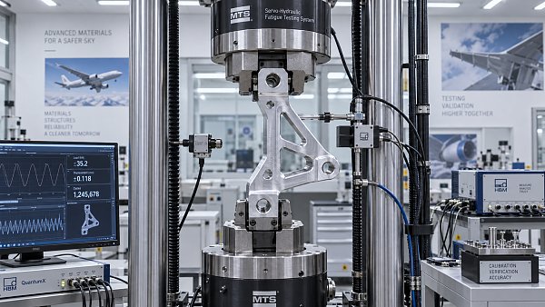
A machining supplier can meet aerospace fatigue testing requirements, but precision CNC equipment and a quality certificate alone do not establish that capability. The supplier must show a controlled chain from raw material receipt through machining, heat treatment, surface finishing, inspection, specimen preparation, test execution, and final record retention. Fatigue performance is highly sensitive to details that can be invisible in a dimensional inspection report.
A part may meet every drawing dimension and still fail prematurely under cyclic loading because of a sharp tool mark, an unfavorable grain-flow direction, residual tensile stress, contamination introduced during processing, or a finishing operation that altered the surface condition. Aerospace fatigue qualification therefore evaluates a manufacturing system, not only a completed part.
Start with the actual fatigue duty cycle
The first question is not whether a supplier has performed “fatigue testing.” It is whether the proposed test represents the component's failure mechanism and service environment. A rotating shaft, thin bracket, landing-gear fitting, actuator housing, turbine-adjacent component, and unmanned aircraft structural joint do not experience fatigue in the same way.
A meaningful test definition identifies the loading mode: axial tension-compression, bending, torsion, internal pressure cycling, vibration, or a combined load. It also establishes the load ratio, peak and minimum stress, cycle frequency, required life, and acceptance criterion. A simple constant-amplitude test can be useful for comparing material or process conditions, but it may not represent a component exposed to irregular flight loads, start-stop thermal cycles, vibration, or occasional overload events.
Load introduction deserves the same scrutiny as the test machine. A fixture that grips a part at a location unlike the installed interface can create bending moments or contact stresses that do not exist in service. Conversely, a fixture that unintentionally restrains a feature may conceal a weakness that appears after installation. The drawing, assembly constraints, fastener preload, mating materials, and expected load path should inform fixture design.
Material traceability must survive every process step
Fatigue data is only credible when it can be tied to a defined material condition. The record should link the finished part or test coupon to its material heat, product form, mill documentation, and receiving verification. Alloy designation is not enough. Bar, plate, forging, extrusion, and additive feedstock can have different microstructures, grain orientation, inclusion behavior, and response to heat treatment.
Material condition must remain visible after stock is cut into smaller pieces. Losing heat-lot identity during internal transfer is a common qualification failure because the final test result can no longer be associated with the source material. Segregation methods, durable identifiers, traveler records, and controlled storage locations matter when several similar alloys are processed in parallel.
The relationship between a production part and a fatigue specimen also needs definition. A coupon machined from a separate bar can validate a material lot, yet it does not necessarily validate the machining route used on a complex part. Where machining-induced surface condition is part of the concern, representative coupons should receive the same operations, tools, coolant regime, cutting parameters, deburring method, heat treatment, and finishing sequence as the critical feature.
Machining details that change fatigue life
Fatigue cracks commonly begin at the surface, especially at geometric transitions. This makes local process control more important than a broad statement such as “fine surface finish.” Surface roughness values are useful, but they do not fully describe the condition of a machined surface. A low average roughness can coexist with a deep isolated score, torn material, smeared metal, embedded abrasive residue, or a directional texture aligned unfavorably with the applied stress.
Tool wear requires particular attention on titanium alloys, nickel-based alloys, high-strength steels, and other materials that generate heat or resist cutting. As an insert degrades, it can increase surface work hardening, alter the cut direction, produce drag marks, or create a local notch at the edge of a feature. A process capable of holding diameter tolerance at the end of a tool’s life is not automatically capable of preserving fatigue-sensitive surface integrity.
Critical transitions should be evaluated as local features rather than generic dimensions. These include:
- fillets at a load-carrying shoulder, where actual radius, blend quality, and tool-path witness marks affect the stress concentration;
- thread runouts, keyways, drilled intersections, and cross-holes, which may combine a geometric notch with burrs or interrupted cutting damage;
- thin-wall pockets and ribs, where clamping force or residual stress release can distort the part after final machining;
- reamed and bored holes used with fasteners or pins, where bore geometry, edge break, surface direction, and installation interference can all influence crack initiation.
Deburring is often underestimated. Hand deburring may remove a sharp edge on one part and roll or gouge it on another. Abrasive media can improve an edge blend but may also change dimensions or leave residue in small passages. A fatigue-critical edge needs an explicit geometry requirement and a repeatable verification method, not an instruction to “remove burrs.”
Heat treatment and finishing cannot be treated as separate certificates
Many aerospace alloys obtain their strength, toughness, corrosion resistance, or residual-stress state from thermal processing. A heat-treatment certificate confirms that a cycle was performed under a defined process, but fatigue relevance also depends on distortion control, quench response, part loading, post-treatment machining allowance, and the condition of the surface after final operations.
For precipitation-hardened materials, a final machining cut after aging can expose a different surface condition than a specimen finished before aging. For hardened steels, grinding burn or excessive local heating can alter the near-surface microstructure even where hardness readings appear acceptable. For aluminum alloys, aggressive removal after treatment can remove a beneficial surface layer or change a fatigue-critical geometry. These are process-sequence questions, not paperwork questions.
Surface treatments need the same traceable connection to the tested configuration. Shot peening, polishing, coating, anodizing, plating, conversion treatments, or chemical milling can alter crack initiation behavior. Compressive residual stress from a controlled peening operation can be beneficial, while uneven coverage, excessive intensity, masking errors, or subsequent machining can reduce that benefit. Coating defects and hydrogen-related risks from some plating processes require evaluation against the relevant material and process specification.
Separate material fatigue from component fatigue
Material fatigue testing answers whether a defined material condition has acceptable cyclic behavior in a controlled specimen geometry. Component fatigue testing addresses whether a specific design, process route, interface, and load path perform as intended. Neither replaces the other.
A polished laboratory specimen often produces a result that cannot be transferred directly to a machined component containing holes, radii, threaded features, press fits, or assembly preload. Conversely, a component-level test that fails at an unexpected fixture contact point may reveal a test setup problem rather than a production limitation. The test report must clearly identify what was actually tested and what conclusion the result supports.
Evidence from the test laboratory
A supplier does not need to operate every fatigue test internally, but outsourced testing must be technically controlled. The machining organization remains responsible for showing that the laboratory used the approved specimen configuration, fixture, instrumentation, environment, cycle counting method, and acceptance logic. Sending an unidentified part to an external lab and retaining only a pass statement leaves major gaps.
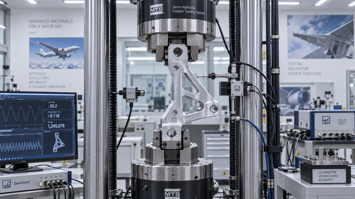
A complete report normally identifies the specimen or part serial number, material lot, heat-treatment condition, drawing revision, process route, test equipment, calibration status, fixture arrangement, load waveform, load ratio, frequency, cycle count, interruptions, environmental conditions, and failure location. Images before and after testing are useful when they show the critical area, but they are not a substitute for the raw test record.
Failure analysis matters as much as a survival result. If a specimen fractures, the investigation should distinguish among a fatigue-origin crack, overload fracture, fixture damage, grip slip, corrosion-assisted initiation, processing defect, and accidental handling damage. Fractography, metallography, dimensional review, and non-destructive inspection may be appropriate based on the part and suspected mechanism. Without identifying the origin, a failure can prompt an expensive but ineffective process change.
Control the variables between qualification and production
A successful qualification test has limited value if production can drift away from the tested condition. The supplier needs a documented configuration baseline: approved material sources or acceptance criteria, machining program revision, critical tools, process parameters where they affect surface integrity, fixture revision, inspection method, heat-treatment route, finishing process, and special-process approvals where applicable.
Changes should be assessed for fatigue impact before release. Replacing a cutting tool grade, increasing material removal rate, moving a feature to another machine, changing coolant chemistry, altering a deburring method, or substituting a heat-treatment source can preserve visible dimensions while changing the initiating surface. The required response may range from engineering review and verification coupons to partial or full requalification, depending on the criticality of the changed feature and the basis of the original approval.
Repeatability is demonstrated with objective records. Capability studies on a noncritical diameter do not prove repeatability at a fatigue-sensitive fillet. Inspection plans should target the features tied to stress concentration and crack initiation: contour radius, bore condition, edge break, surface integrity indicators, coating coverage, and residual-stress-affecting operations. Non-destructive examination can detect certain discontinuities, but it cannot certify the absence of every fatigue risk created by machining.
Questions that expose a real capability
Technical review becomes more effective when requests seek evidence rather than broad declarations. Ask for a traceability example that follows one part from incoming stock through shipment. Request a representative route card and identify where lot identity is retained, where inspection occurs, and which operations can alter surface condition. Review a redacted fatigue report for completeness, including fixture information and the reason the selected test represents the application.
It is also useful to compare the supplier’s proposed inspection method with the stated failure risk. If the concern is a drilled-hole initiation site, a general final visual inspection is weak evidence. If the concern is residual tensile stress after aggressive machining, a dimensional report alone cannot resolve it. The appropriate evidence must be connected to the suspected mechanism.
Capability is credible when the supplier can define the relevant fatigue mechanism, reproduce the tested manufacturing condition, and maintain records that connect each delivered part to that condition. Where any of those links is missing, the result may still be useful engineering information, but it should not be treated as proof that production parts satisfy aerospace fatigue requirements.
Search News
Hot Articles
- Carbon Fiber StructuresHow to Specify Aerospace Carbon Fiber Assemblies for Lightweight, Load-Bearing PartsJul 11, 2026
- Machine VisionXiaomi, Alibaba DAMO Academy Drive Open-Source Robotics Model Ecosystem, Lowering Algorithm Development Barriers for Overseas SMEs Adopting Chinese Robotics SolutionsMar 30, 2026
- Cobots & ArmsShanxi 'AI+' Conference Showcases Embodied Intelligence with Multinational Buyer Engagement: Key Industry ImplicationsMar 30, 2026
Popular Tags
Recommended News
 Jul 11, 2026How to Specify Aerospace Carbon Fiber Assemblies for Lightweight, Load-Bearing PartsAerospace carbon fiber assemblies: learn how to specify laminate design, load data, joining methods, and inspection controls for lighter, reliable load-bearing aerospace parts.Elena Rostova (UAV Systems Researcher)
 Mar 30, 2026Xiaomi, Alibaba DAMO Academy Drive Open-Source Robotics Model Ecosystem, Lowering Algorithm Development Barriers for Overseas SMEs Adopting Chinese Robotics SolutionsXiaomi & Alibaba DAMO Academy's open-source robotics models lower algorithm barriers for global SMEs. Boost efficiency in manufacturing, logistics & smart retail with ROS 2 compatible solutions.TSV Data Lab
 Mar 30, 2026Shanxi 'AI+' Conference Showcases Embodied Intelligence with Multinational Buyer Engagement: Key Industry ImplicationsShanxi 'AI+' Conference highlights embodied intelligence with Tesla, Ubtech & Jiantao showcasing multimodal robotics. 40+ global buyers validated tech on-site, creating new B2B channels for industrial automation & AI solutions.Chen Wei (Automation Lead Engineer)
 Mar 30, 2026Zhongguancun Unveils 6G Integrated Sensing-Computing-Intelligence Platform to Empower Embodied Robots for Global Industrial ApplicationsZhongguancun's new 6G platform revolutionizes industrial robotics with <10ms latency, empowering global automotive, logistics & port automation. Discover how this tech boosts China's smart manufacturing exports.TSV Data Lab
 Mar 30, 2026Mech-Mind Tianjin Embodied Intelligence R&D and Production Base Goes Live, Cutting Delivery Time by 20%–30% for Global Customized AMR+Vision SolutionsMech-Mind's Tianjin AMR+Vision production base cuts delivery time by 20%-30% for欧美 & Latin American markets. Discover how this PLd-certified facility accelerates customized robotics solutions for smart manufacturing and logistics.Chen Wei (Automation Lead Engineer)
 Mar 30, 2026Boao Forum Reveals 'Co-evolution of Big and Small Brains' Trend in Humanoid Robots, China's Embodied Intelligence Accelerates Adaptation to Overseas Manufacturing Service ScenariosDiscover how China's humanoid robots, featuring 'Co-evolution of Big and Small Brains,' are revolutionizing global manufacturing. Learn about Embodied Tian Gong 3.0's ISO compliance and overseas deployment at Boao Forum 2026.Chen Wei (Automation Lead Engineer)
 Mar 30, 2026China Railway Industrial Secures Patent for Embodied Robotics in Material Handling, Boosting High-Precision Delivery Capabilities for Overseas Infrastructure and Manufacturing ProjectsChina Railway Industrial's new patent for embodied robotics in material handling boosts high-precision delivery for global infrastructure & manufacturing. Discover how this innovation enhances logistics accuracy in automotive, rail transit & EPC projects.Chen Wei (Automation Lead Engineer)
 Oct 02, 2026How to Qualify Machined Parts Suppliers for Hard Tech ProgramsHard tech supply chain machined parts demand rigorous supplier qualification. Learn how to assess capability, traceability, quality controls, and delivery resilience.Dr. Marcus Vance
 Oct 01, 2026How to Select an Outdoor Security Radar Sensor for Perimeter Detection?Outdoor security radar sensor selection guide: compare range, accuracy, false-alarm control, integration, and field testing for reliable perimeter detection.TSV Data Lab
 Sep 30, 2026How to Evaluate Solid-State LiDAR Hardware for Outdoor Autonomous VehiclesSolid state LiDAR hardware evaluation guide for outdoor autonomous vehicles—compare range, point-cloud quality, environmental resilience, integration, and safety.TSV Data Lab
 Sep 29, 2026ISO 9283 Repeatability: How to Evaluate Cobot Positioning PerformanceISO 9283 cobot repeatability explained: learn how payload, reach, approach direction, and test conditions affect positioning performance and cell capability.Chen Wei (Automation Lead Engineer)
 Oct 01, 2026Can a Machining Supplier Meet Aerospace Fatigue Testing Requirements?Can a machining supplier meet aerospace fatigue testing requirements? Learn the traceability, process control, and test evidence needed for reliable aerospace parts.Dr. Marcus Vance
 Sep 30, 2026Which Industrial Robot Specifications Matter for High-Precision Assembly?Which industrial robot specifications matter most for high-precision assembly? Explore repeatability, accuracy, stiffness, vibration, calibration, and force control for reliable yields.Chen Wei (Automation Lead Engineer)
 Sep 29, 2026How Do You Verify Servo Motor Torque Under Continuous Load?How do I verify servo motor torque under continuous load? Learn RMS torque checks, torque-speed limits, thermal derating, and real-machine testing.Chen Wei (Automation Lead Engineer)
 Oct 02, 2026ZD330 Software Configuration: Verifying Cut-List Import Before PurchaseZD330 software and machine configuration: verify cut-list imports, data mapping, labels, and workflow before purchase to reduce errors and choose with confidence.Victor Lin (Chief Software Architect)
 Sep 28, 2026Spindle Runout Measurement in Germany: DIN Standards, Methods, and Acceptance LimitsSpindle runout measurement Germany: explore DIN standards, proven methods, acceptance limits, and audit-ready practices for reliable machining quality.Dr. Marcus Vance
 Sep 27, 2026How to Select Wall-Mount Edge Devices for Space-Constrained Factory NetworksWall mount edge devices for space-constrained factories: evaluate workload, thermal design, power resilience, cable access, and network reliability for smarter deployments.TSV Data Lab
 Sep 26, 2026Machining Tolerance Analysis: How to Set Limits That Meet Function and Cost TargetsMachining tolerance analysis: learn how to set functional limits, control tolerance stacks, reduce inspection risk, and balance precision with production cost.Dr. Marcus Vance
 Sep 25, 2026How to Evaluate an Industrial Infrastructure Data Platform for Multi-Site OperationsIndustrial infrastructure data platform evaluation guide for multi-site operations: compare data quality, edge resilience, interoperability, governance, and scalable proof-of-value criteria.Victor Lin (Chief Software Architect)
 Sep 24, 2026How to Select Machine Vision Optics for Accurate Inspection at Different Working DistancesMachine vision optics selection guide for accurate inspection at every working distance. Compare FOV, pixel scale, DOF, distortion, lighting, and telecentric options.TSV Data Lab
 Sep 23, 2026How to Evaluate a Machine Vision System Integrator for High-Speed Inspection LinesChoose a machine vision system integrator with proven expertise in high-speed inspection, reliable reject timing, robust optics, and measurable acceptance criteria.TSV Data Lab
 Oct 01, 2026What is included in a robotic system integration project cost?Robotic system integration project cost explained: compare equipment, engineering, safety, testing, installation, and lifecycle factors for smarter automation investments.Chen Wei (Automation Lead Engineer)
 Sep 30, 2026How much does warehouse automation cost for a growing distribution center?How much does warehouse automation cost? Explore equipment, integration, facility upgrades, lifecycle expenses, and ROI factors for a growing distribution center.Chen Wei (Automation Lead Engineer)
 Sep 29, 2026How MES and OEE work together to identify production lossesMES and OEE work together to uncover hidden production losses, connect downtime, speed, and quality data, and drive smarter shop-floor improvements.Victor Lin (Chief Software Architect)