Which Industrial Robot Specifications Matter for High-Precision Assembly?
Publication Date
author
The industrial robot specifications that matter most for high-precision assembly are repeatability, absolute positioning accuracy, structural stiffness, vibration behavior, controller performance, and calibration stability. Payload and reach still matter, but they do not determine whether a robot can place a delicate component consistently, align a connector without damaging it, or maintain yield across long production runs.
The first practical rule is simple: do not select a robot from its catalog accuracy line alone. High-precision assembly is a system outcome. The robot, end effector, fixture, vision system, cable routing, payload inertia, process force, temperature changes, and calibration method all contribute to the final position of the part. A robot with an impressive published specification can still produce poor assembly results when these surrounding conditions are not controlled.
Start with the assembly tolerance, not the robot brochure
Before comparing robot models, define what the process must achieve at the part level. “Precision assembly” can mean very different things. Placing a plastic housing into a locating nest may tolerate a relatively broad positional window. Seating a miniature connector, engaging a press-fit component, bonding an optical element, or aligning a camera module may allow far less variation and may also require controlled force.
Write the actual acceptance condition in operational terms. This should include the permitted position and orientation error, the required insertion or placement force, the inspection method, the takt-time target, and whether the process must recover from variation in incoming parts. That definition tells you whether the robot needs to be inherently precise, whether vision can correct for part variation, or whether a compliant end effector and force feedback are more important than tighter nominal positioning.
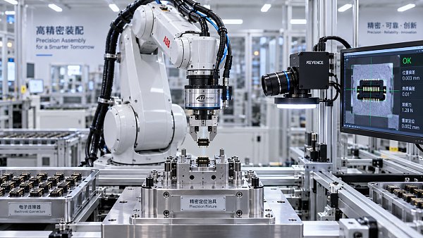
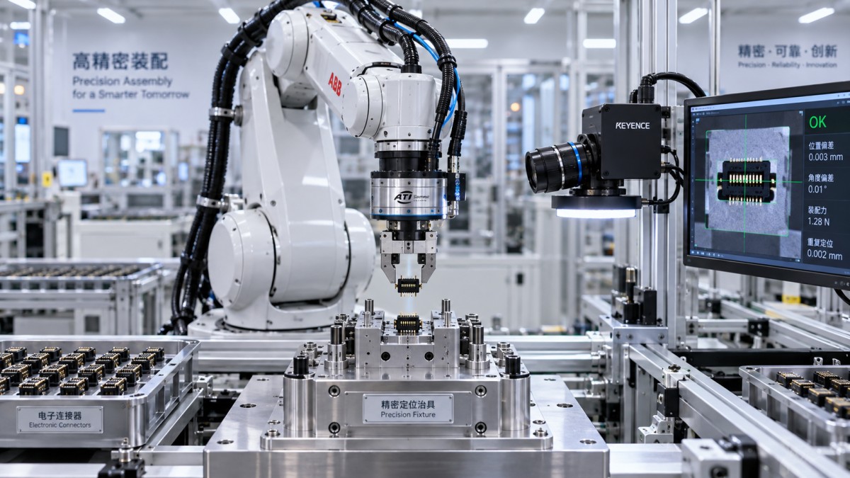
A common mistake is treating the robot as the only precision device in the cell. In reality, a robot often transfers a part into a precisely designed fixture, where pins, nests, chamfers, or guiding features establish the final location. In that situation, repeatable approach motion and controlled force may matter more than exceptional absolute path accuracy. Conversely, a robot performing dispensing, laser processing, adhesive placement, or free-space vision-guided work has fewer mechanical references. Its absolute accuracy and calibration quality become more consequential.
Repeatability is the first specification to understand
Repeatability describes how closely the robot returns to the same taught position after repeating the same motion under defined conditions. It is usually the most useful initial metric for repetitive assembly because a production robot often follows a known sequence: pick, present, insert, release, and return.
Repeatability is not the same as accuracy. A robot can return to nearly the same location every cycle while that location remains offset from the desired coordinate in the real world. For a fixture-based process, this may be entirely workable: the robot can be taught relative to the fixture, and the fixture handles final part location. For an operation that depends on a CAD coordinate, a machine-vision coordinate frame, or an interchangeably programmed cell, the offset becomes a problem.
When reviewing repeatability, ask how the value was obtained. Published numbers often assume controlled payload, speed, posture, temperature, and test trajectory. Your production cycle may involve a long reach, an offset tool, frequent direction changes, or a rapidly moving wrist. Those conditions can expose deflection and settling behavior not evident in a simplified specification.
Repeatability should also be evaluated at the actual working posture. Industrial robots do not behave uniformly throughout their workspace. A pose near the center of the working envelope can be more stable than a fully extended pose, while certain joint configurations may be more sensitive to small changes in load or cable tension. Request validation at the same reach, orientation, cycle speed, and payload geometry planned for production.
Absolute positioning accuracy matters when coordinates must transfer
Absolute positioning accuracy is the difference between the robot’s commanded position and its actual physical position in a shared reference frame. This specification matters when a robot must move accurately without being individually retaught at every station, when multiple robots share coordinates, or when it works with external equipment such as vision systems, machining centers, inspection stations, or conveyors.
It is especially relevant in modular production cells. A process may be commissioned in one factory, copied to another, and expected to run with limited retuning. Strong absolute accuracy, together with a robust calibration procedure, reduces the amount of manual coordinate correction required during deployment.
Do not assume absolute accuracy alone solves integration problems. The robot base must be installed in a known location, the tool center point must be measured correctly, and the fixture coordinate system must be stable. A small error in tool-center-point definition can appear as a much larger placement error when the wrist changes orientation. Likewise, a fixture moved during maintenance can invalidate a carefully established coordinate relationship.
For high-precision applications, treat robot, tool, fixture, and sensor frames as a single geometric chain. Each link needs a defined reference method and a controlled way to check for drift.
Stiffness and deflection determine what happens under load
A robot’s static position may look acceptable until the process applies force. Insertion, pressing, scraping, probing, gasket fitting, and connector mating all introduce loads that can bend the arm, wrist, tool adapter, or end effector. This is where joint stiffness becomes more meaningful than a simple unloaded repeatability claim.
Stiffness is the resistance to deflection when force or torque is applied. It varies with robot posture, load direction, arm extension, and joint configuration. A long, slender tool magnifies the effect because small angular movement at the wrist creates a larger displacement at the tool tip. A robot that is sufficiently rigid for pick-and-place may not be appropriate for a force-sensitive insertion process at its maximum reach.
Assess the complete load, not just the part mass. Include the gripper, tool changer, mounting plate, sensors, hoses, cables, and the distance from the wrist flange to the combined center of gravity. An end effector can remain within the robot’s rated payload while still creating difficult inertia or moment loads. Rapid acceleration and deceleration make those issues more visible.
When assembly requires contact, consider whether the cell should use passive compliance, active force control, or both. Passive compliance can absorb small alignment errors and protect fragile parts. Active force or torque sensing can detect contact, guide a controlled insertion, identify an obstruction, or verify seating. These features do not replace sound mechanics, but they can make a process more tolerant of normal part and fixture variation.
Vibration and settling time can undermine a fast cycle
A robot can reach a target quickly yet still be moving at the tool tip. Oscillation after a rapid stop may be insignificant for palletizing, but it can affect a vision inspection, adhesive bead start point, micro-fastening operation, or precision placement. The relevant question is not only how fast the robot moves; it is how quickly the tool reaches a stable state that the process can tolerate.
Vibration is influenced by arm posture, acceleration settings, payload inertia, tool length, mounting rigidity, floor condition, and nearby equipment. A flexible pedestal or poorly designed tool plate can introduce more error than the robot mechanism itself. Cable bundles may also apply changing force to the wrist, particularly in compact cells where the robot makes repeated high-angle movements.
Testing should therefore include production motion profiles. Run the intended cycle, not a slow demonstration path. Measure placement results after the robot has accelerated, decelerated, changed direction, and operated for a meaningful period. If vision is involved, observe whether the image is captured after the assembly has truly settled rather than merely after a programmed delay.
Higher speed is not automatically better. In a precision cell, a slightly slower and more stable approach can improve yield enough to outweigh a marginal reduction in raw motion time. The best cycle is the fastest one that remains capable and repeatable under normal manufacturing variation.
Controller response and motion functions shape the process window
The controller affects how precisely the robot executes trajectories, blends moves, responds to sensor input, and coordinates with other equipment. For assembly, examine the available motion modes rather than assuming every controller behaves the same way.
Useful capabilities may include controlled linear motion, smooth transition management, externally triggered motion, force-guided routines, conveyor tracking, and interfaces for vision or inspection equipment. The value of each feature depends on the process. A simple fixture-guided insertion may only need consistent linear approach motion. A vision-guided operation may need reliable coordinate transformation and predictable communication timing. A press-fit process may need force thresholds and a clear fault response.
Controller communication performance should be judged in context. A fast network does not guarantee a precise process if sensor processing, vision calculation, robot command execution, and mechanical settling are poorly synchronized. Map the full sequence: image capture, pose calculation, command transmission, robot movement, contact detection, and quality confirmation. Latency and timing variation are most important where the workpiece is moving or where a correction must happen during the motion.
Calibration stability is a production specification, not a commissioning task
Calibration often receives intense attention during cell setup and too little attention afterward. Yet high-precision assembly depends on the relationship between the robot, its tool, and the fixture remaining valid over time. Tool changes, collisions, maintenance work, thermal expansion, base movement, and changes in end-effector hardware can all shift that relationship.
Tool center point calibration deserves particular care. The robot may be capable of returning its flange consistently, but assembly occurs at the gripper fingers, suction cup, screwdriver bit, dispensing needle, or sensor probe. If the tool center point or tool orientation is wrong, position errors will vary as the wrist rotates. This is often misdiagnosed as poor robot repeatability.
Build verification into the operating plan. A practical cell includes a repeatable reference feature or master part that can be checked after a tool change, after maintenance, and at a suitable production interval. The purpose is not to add inspection for its own sake. It is to distinguish robot drift, fixture movement, tool wear, and part variation before those conditions become a yield problem.
How to compare robots without being misled by headline specifications
Use the same application conditions for every candidate robot. A short evaluation checklist prevents comparisons that look objective but are based on incompatible catalog claims.
- Define the required tool-tip position and orientation tolerance at the actual assembly point.
- Specify the full end-of-arm load, including its center of gravity and inertia.
- Identify the working postures, especially the farthest reach and most demanding wrist orientations.
- Separate fixture-located operations from free-space or vision-guided operations.
- List contact forces, insertion directions, and allowable part damage.
- Run representative cycle speeds and check results after motion settling.
- Document the coordinate frames and the method for recalibrating them.
- Define what a successful trial must prove: placement capability, insertion success, inspection pass rate, recovery behavior, or all of these.
This approach also clarifies when a conventional industrial robot, a collaborative robot, a Cartesian system, or a dedicated precision stage is appropriate. A compact articulated robot can be an effective choice when it must approach a part from multiple angles and work within a constrained cell. A Cartesian system may be easier to control for a planar process with a simple rectangular workspace. A dedicated precision stage may be the better engineering choice where the required tolerance is beyond what an articulated arm can reliably provide in the intended environment.
Do not confuse a vision system with a precision upgrade
Machine vision can compensate for part position variation, identify orientation, and update robot coordinates. It cannot remove mechanical deflection, poor fixture repeatability, camera calibration errors, or vibration at the moment of placement. It also has its own error sources: lighting changes, surface reflectivity, lens distortion, depth uncertainty, and inconsistent image features.
The most reliable vision-guided assembly cells divide responsibility clearly. Vision identifies where the part is. The robot brings the tool to the calculated region with stable motion. The fixture or compliance mechanism resolves the final mechanical interface. Force or process feedback confirms the operation succeeded. Asking one subsystem to compensate for every other weakness creates an unstable process.
What to request before committing to a robot
Ask suppliers for application-specific evidence, not broad statements about suitability for precision work. Request performance information at the intended payload and reach, documentation for calibration and tool definition, constraints on force-control functions, and guidance on mounting requirements. If the process is critical, plan a representative trial using actual parts, realistic tooling, and the planned cycle profile.
The trial should include variation deliberately. Test normal incoming part variation, different fixture positions within their allowed condition, production-level speed, and repeated cycles. Observe not only whether the robot completes the motion, but whether the finished assembly meets the acceptance requirement and whether a failure is detected and handled predictably.
This is also the point where independent technical benchmarking can be valuable. TechStat Vanguard’s engineering-first approach is relevant because robot selection should be based on measured repeatability, calibration behavior, controller limits, and system conditions rather than undefined claims of “high precision.” The useful comparison is the one tied to the process window your assembly line actually needs.
A high-precision robot cell succeeds when its specifications are translated into process capability. Select the arm only after defining the part tolerance, working posture, tool load, force requirement, and verification method. That order prevents a costly but common outcome: buying a robot that appears precise on paper, then spending months compensating for limits that were visible in the application requirements from the beginning.
Search News
Hot Articles
- Carbon Fiber StructuresHow to Specify Aerospace Carbon Fiber Assemblies for Lightweight, Load-Bearing PartsJul 11, 2026
- Machine VisionXiaomi, Alibaba DAMO Academy Drive Open-Source Robotics Model Ecosystem, Lowering Algorithm Development Barriers for Overseas SMEs Adopting Chinese Robotics SolutionsMar 30, 2026
- Cobots & ArmsShanxi 'AI+' Conference Showcases Embodied Intelligence with Multinational Buyer Engagement: Key Industry ImplicationsMar 30, 2026
Popular Tags
Recommended News
 Jul 11, 2026How to Specify Aerospace Carbon Fiber Assemblies for Lightweight, Load-Bearing PartsAerospace carbon fiber assemblies: learn how to specify laminate design, load data, joining methods, and inspection controls for lighter, reliable load-bearing aerospace parts.Elena Rostova (UAV Systems Researcher)
 Mar 30, 2026Xiaomi, Alibaba DAMO Academy Drive Open-Source Robotics Model Ecosystem, Lowering Algorithm Development Barriers for Overseas SMEs Adopting Chinese Robotics SolutionsXiaomi & Alibaba DAMO Academy's open-source robotics models lower algorithm barriers for global SMEs. Boost efficiency in manufacturing, logistics & smart retail with ROS 2 compatible solutions.TSV Data Lab
 Mar 30, 2026Shanxi 'AI+' Conference Showcases Embodied Intelligence with Multinational Buyer Engagement: Key Industry ImplicationsShanxi 'AI+' Conference highlights embodied intelligence with Tesla, Ubtech & Jiantao showcasing multimodal robotics. 40+ global buyers validated tech on-site, creating new B2B channels for industrial automation & AI solutions.Chen Wei (Automation Lead Engineer)
 Mar 30, 2026Zhongguancun Unveils 6G Integrated Sensing-Computing-Intelligence Platform to Empower Embodied Robots for Global Industrial ApplicationsZhongguancun's new 6G platform revolutionizes industrial robotics with <10ms latency, empowering global automotive, logistics & port automation. Discover how this tech boosts China's smart manufacturing exports.TSV Data Lab
 Mar 30, 2026Mech-Mind Tianjin Embodied Intelligence R&D and Production Base Goes Live, Cutting Delivery Time by 20%–30% for Global Customized AMR+Vision SolutionsMech-Mind's Tianjin AMR+Vision production base cuts delivery time by 20%-30% for欧美 & Latin American markets. Discover how this PLd-certified facility accelerates customized robotics solutions for smart manufacturing and logistics.Chen Wei (Automation Lead Engineer)
 Mar 30, 2026Boao Forum Reveals 'Co-evolution of Big and Small Brains' Trend in Humanoid Robots, China's Embodied Intelligence Accelerates Adaptation to Overseas Manufacturing Service ScenariosDiscover how China's humanoid robots, featuring 'Co-evolution of Big and Small Brains,' are revolutionizing global manufacturing. Learn about Embodied Tian Gong 3.0's ISO compliance and overseas deployment at Boao Forum 2026.Chen Wei (Automation Lead Engineer)
 Mar 30, 2026China Railway Industrial Secures Patent for Embodied Robotics in Material Handling, Boosting High-Precision Delivery Capabilities for Overseas Infrastructure and Manufacturing ProjectsChina Railway Industrial's new patent for embodied robotics in material handling boosts high-precision delivery for global infrastructure & manufacturing. Discover how this innovation enhances logistics accuracy in automotive, rail transit & EPC projects.Chen Wei (Automation Lead Engineer)
 Sep 30, 2026How to Evaluate Solid-State LiDAR Hardware for Outdoor Autonomous VehiclesSolid state LiDAR hardware evaluation guide for outdoor autonomous vehicles—compare range, point-cloud quality, environmental resilience, integration, and safety.TSV Data Lab
 Sep 29, 2026ISO 9283 Repeatability: How to Evaluate Cobot Positioning PerformanceISO 9283 cobot repeatability explained: learn how payload, reach, approach direction, and test conditions affect positioning performance and cell capability.Chen Wei (Automation Lead Engineer)
 Sep 30, 2026Which Industrial Robot Specifications Matter for High-Precision Assembly?Which industrial robot specifications matter most for high-precision assembly? Explore repeatability, accuracy, stiffness, vibration, calibration, and force control for reliable yields.Chen Wei (Automation Lead Engineer)
 Sep 29, 2026How Do You Verify Servo Motor Torque Under Continuous Load?How do I verify servo motor torque under continuous load? Learn RMS torque checks, torque-speed limits, thermal derating, and real-machine testing.Chen Wei (Automation Lead Engineer)
 Sep 28, 2026Spindle Runout Measurement in Germany: DIN Standards, Methods, and Acceptance LimitsSpindle runout measurement Germany: explore DIN standards, proven methods, acceptance limits, and audit-ready practices for reliable machining quality.Dr. Marcus Vance
 Sep 27, 2026How to Select Wall-Mount Edge Devices for Space-Constrained Factory NetworksWall mount edge devices for space-constrained factories: evaluate workload, thermal design, power resilience, cable access, and network reliability for smarter deployments.TSV Data Lab
 Sep 26, 2026Machining Tolerance Analysis: How to Set Limits That Meet Function and Cost TargetsMachining tolerance analysis: learn how to set functional limits, control tolerance stacks, reduce inspection risk, and balance precision with production cost.Dr. Marcus Vance
 Sep 25, 2026How to Evaluate an Industrial Infrastructure Data Platform for Multi-Site OperationsIndustrial infrastructure data platform evaluation guide for multi-site operations: compare data quality, edge resilience, interoperability, governance, and scalable proof-of-value criteria.Victor Lin (Chief Software Architect)
 Sep 24, 2026How to Select Machine Vision Optics for Accurate Inspection at Different Working DistancesMachine vision optics selection guide for accurate inspection at every working distance. Compare FOV, pixel scale, DOF, distortion, lighting, and telecentric options.TSV Data Lab
 Sep 23, 2026How to Evaluate a Machine Vision System Integrator for High-Speed Inspection LinesChoose a machine vision system integrator with proven expertise in high-speed inspection, reliable reject timing, robust optics, and measurable acceptance criteria.TSV Data Lab
 Sep 30, 2026How much does warehouse automation cost for a growing distribution center?How much does warehouse automation cost? Explore equipment, integration, facility upgrades, lifecycle expenses, and ROI factors for a growing distribution center.Chen Wei (Automation Lead Engineer)
 Sep 29, 2026How MES and OEE work together to identify production lossesMES and OEE work together to uncover hidden production losses, connect downtime, speed, and quality data, and drive smarter shop-floor improvements.Victor Lin (Chief Software Architect)
 Sep 28, 2026When is a SCADA API the right choice for connecting plant systems?SCADA API guide: learn when governed plant data integration improves traceability, security, and scalability—without compromising real-time control.Victor Lin (Chief Software Architect)
 Sep 27, 2026How SCADA data integration improves traceability across production linesSCADA data integration connects production-line data to improve traceability, accelerate quality investigations, and strengthen safety decisions.Victor Lin (Chief Software Architect)
 Sep 26, 2026What to define before starting SCADA integration planningSCADA integration planning starts with clear scope, control boundaries, data models, cybersecurity, and testing. Discover the definitions that reduce risk and costly rework.Victor Lin (Chief Software Architect)
 Sep 25, 2026How a smart factory with Industrial IoT reduces production blind spotsDiscover how a smart factory with Industrial IoT turns real-time machine, quality, and workflow data into actionable insights that reduce production blind spots and delivery risks.Victor Lin (Chief Software Architect)
 Sep 24, 2026When does Industrial IoT make smart manufacturing easier to scale?Smart manufacturing Industrial IoT scales when trusted data, interoperable systems, and secure workflows turn connected assets into measurable gains.TSV Data Lab