How Do You Verify Servo Motor Torque Under Continuous Load?
Publication Date
author
How Do You Verify Servo Motor Torque Under Continuous Load?
How do I verify servo motor torque under continuous load? Start by comparing the required RMS torque with the motor’s continuous torque rating at the real operating speed.
A catalog peak-torque figure is not enough. Continuous operation depends on thermal behavior, duty cycle, acceleration demand, transmission losses, ambient temperature, and the controller’s operating limits.
For automation engineers, machine builders, and procurement teams, the goal is simple: prove that the servo system can sustain the required motion profile without overheating.
That proof should combine calculations, manufacturer torque-speed data, measured current, temperature testing, and a realistic assessment of mechanical load variation throughout the production cycle.
Start With the Correct Torque Question
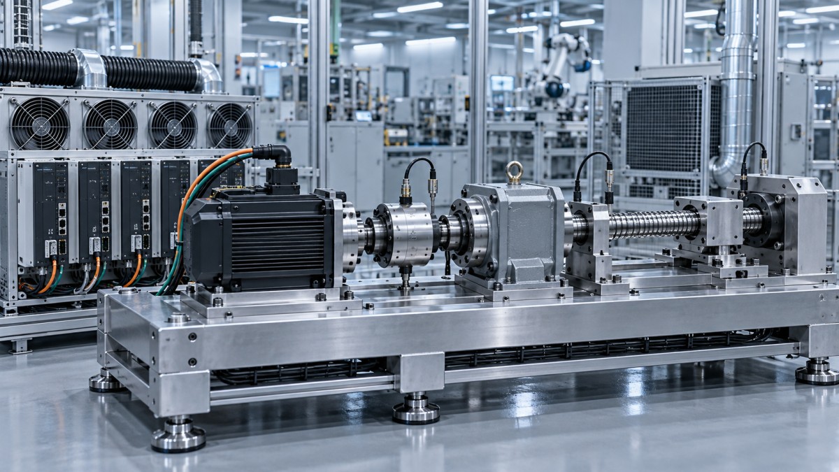
The first mistake is asking whether a motor can produce the required torque once. The useful question is whether it can repeatedly produce that torque indefinitely.
Servo motor selection normally involves three different torque values: peak torque, intermittent torque, and continuous torque. Each represents a different electrical and thermal operating condition.
Peak torque supports short acceleration events, emergency corrections, or transient disturbances. It may be available for milliseconds or seconds, depending on the motor, drive, and cooling conditions.
Continuous torque is the critical value for sustained loading. It indicates the torque a motor can deliver at a stated speed and ambient condition without exceeding permitted winding temperature.
Intermittent torque sits between those limits. It can support recurring loads only when the duty cycle leaves enough low-load time for the motor to reject heat.
Therefore, torque verification should never rely on a single maximum-load calculation. Engineers must convert the complete operating cycle into an RMS torque requirement.
This distinction matters especially in conveyors, winding systems, robotic axes, indexing tables, pumps, packaging equipment, and vertical applications where loaded dwell periods are common.
Calculate Load Torque Before Selecting the Motor
Accurate verification begins with the driven mechanism. Determine the torque required at the motor shaft after accounting for inertia, friction, process force, gravity, and transmission efficiency.
For rotary loads, acceleration torque is commonly calculated as load inertia multiplied by angular acceleration. The resulting value changes whenever acceleration time, payload, or reflected inertia changes.
For linear axes, first calculate the force needed to accelerate the moving mass, overcome friction, resist process loads, and counter gravity where applicable.
Convert linear force into motor torque using the screw lead, pulley radius, rack geometry, or gearbox ratio. Include efficiency values from credible supplier data.
A simple gearbox assumption can create a serious error. Gearbox efficiency is not always constant and may fall under high load, low speed, unfavorable lubrication, or reverse motion.
Friction must also be measured or conservatively estimated. Seal drag, cable carriers, bearing preload, guide contamination, and misalignment can materially increase continuous demand.
For vertical axes, gravity torque deserves particular attention. Holding a suspended load may require substantial continuous current even when the axis is stationary.
Do not assume the brake replaces motor torque during active positioning. A holding brake is generally a safety device, not a precision control element for normal operation.
Use RMS Torque to Represent the Full Duty Cycle
RMS torque converts a changing motion profile into a single thermally equivalent value. It is the most important calculation for verifying continuous servo motor suitability.
The standard calculation squares each torque level, multiplies it by its duration, sums all segments, divides by total cycle time, and takes the square root.
In practical terms, high-torque periods matter disproportionately because torque is squared. A short overload can influence heating far more than its percentage of cycle time suggests.
Include acceleration, constant-speed travel, deceleration, dwell, load holding, reversal, and process-contact stages. Omitting dwell torque is particularly dangerous in force-controlled or vertical machinery.
Regenerative deceleration also belongs in the calculation. Although the motor may generate power during braking, winding current and thermal stress can still be significant.
Use the torque at the motor shaft, rather than torque at the load. If a gearbox is fitted, reflect load inertia and load torque through the ratio correctly.
For a preliminary design, calculate RMS torque from the expected motion profile. Before release, validate it using actual cycle times and measured operating current.
A strong design typically keeps required RMS torque below the motor’s rated continuous torque with a defined engineering margin, rather than operating continuously at the catalog boundary.
Read the Torque-Speed Curve, Not Just the Nameplate
Continuous torque is often limited by speed. As motor speed rises, available continuous torque may decline because of voltage limits, back electromotive force, and drive capability.
The motor nameplate may show a nominal continuous torque value, but the relevant figure is the available continuous torque at your required shaft speed.
Review the manufacturer’s torque-speed envelope for the exact motor and drive combination. A motor paired with a different drive may have different voltage and current limits.
Check whether the published curve assumes natural convection, forced-air cooling, mounting to a specified heat sink, or a particular ambient temperature.
At low speed, a servo motor can still generate substantial heat because cooling from shaft rotation is limited. This is important for pressing, tensioning, and holding applications.
At high speed, mechanical losses, iron losses, and voltage limits become more important. A motor that passes an RMS check may still fail to deliver required torque at speed.
For applications above rated speed, confirm field-weakening operation, available torque, encoder performance, rotor mechanical limits, and the effect of reduced torque margin.
Always distinguish between a motor’s rated speed, maximum speed, and useful continuous operating region. Maximum speed is not evidence of continuous-load capability.
Account for Temperature, Mounting, and Cooling
Servo torque verification is ultimately a thermal verification. Copper losses rise with current, and winding temperature determines insulation life, magnet condition, and long-term motor reliability.
Most continuous torque ratings are based on specific test conditions. A motor installed inside a sealed cabinet or compact machine frame may dissipate heat differently.
Ambient temperature is a direct derating factor. A motor rated at a standard laboratory ambient may require reduced continuous torque in hot production areas.
Mounting matters because the flange and machine structure can act as a heat path. An undersized adapter plate may trap heat and invalidate assumptions.
Forced cooling can increase available continuous torque, but it should be treated as an engineered subsystem. Verify airflow, filter maintenance, fan failure detection, and contamination exposure.
Nearby heat sources can also alter performance. Gearboxes, process heaters, electrical enclosures, and poor air circulation may increase motor temperature beyond expected values.
Use the manufacturer’s thermal derating curves whenever available. If the documentation is incomplete, request test conditions instead of assuming that all rated values are directly comparable.
For high-consequence systems, measure case temperature and, where supported, winding temperature or motor thermal model data during a representative endurance test.
Verify Peak Torque, Drive Current, and Overload Duration
Passing the continuous torque check does not guarantee acceptable dynamic performance. The motor and drive must also supply peak torque during acceleration, disturbance rejection, and rapid reversals.
Compare the maximum required torque with the permitted motor peak torque at speed. Then confirm that the drive can supply the associated peak current.
Drives have their own overload limits. A motor may theoretically tolerate a torque pulse that the selected amplifier cannot deliver for the required duration.
Review overload curves carefully. Some drives permit high current for several seconds, while others reduce available output quickly because of internal thermal protection.
Repeated high-current pulses can create a hidden thermal problem in both the motor and drive. The machine may run briefly but fault after extended production.
Confirm the DC bus and regeneration strategy during deceleration. Excess regenerative energy can trigger overvoltage faults even when the motor torque calculation is correct.
For vertical systems, evaluate power-loss behavior separately. The servo may hold the load during normal operation, while the brake must safely secure it after disablement.
Peak verification should include worst-case supply voltage, maximum payload, cold lubricant, process overload, and the shortest credible acceleration time commanded by the controller.
Measure Current and Temperature on the Actual Machine
Calculation identifies likely risks, but commissioning data verifies the final system. Measure motor current, speed, torque estimate, and temperature under realistic production conditions.
Most modern servo drives report actual torque or current through commissioning software, fieldbus diagnostics, or data logging. Capture multiple complete cycles rather than isolated snapshots.
Use RMS current as a practical validation metric because motor torque is approximately proportional to current within the normal operating range of permanent-magnet servo motors.
Compare measured RMS current with the motor’s continuous current rating. Also examine individual peaks, duration above rated current, and any drive thermal utilization indicators.
Run the test at maximum payload, highest expected cycle rate, and the warmest realistic ambient condition. Cold startup data often understates continuous thermal stress.
Allow enough time for temperatures to stabilize. A motor may appear acceptable during a fifteen-minute test but exceed thermal limits after several hours of operation.
Infrared imaging can reveal poor heat transfer, overloaded connectors, gearbox heat, and hot spots. Confirm emissivity assumptions or supplement thermal images with contact measurements.
Document the test profile, ambient temperature, mounting arrangement, payload, gearing, firmware settings, and measured values. This evidence supports design release and supplier qualification.
Set a Practical Engineering Margin
There is no universal torque margin because machine risk, operating environment, load uncertainty, and expected service life differ. However, zero margin is rarely defensible.
A moderate application with stable loads may need less reserve than a high-throughput machine exposed to payload variation, contamination, temperature swings, or frequent operator adjustments.
Margin should cover real uncertainty, not compensate for poor modeling. Identify the source of uncertainty: friction variation, payload tolerance, process force, gearbox efficiency, or cooling conditions.
For critical equipment, evaluate a worst-case operating envelope rather than a single nominal condition. This approach reveals whether margin remains available across credible extremes.
Oversizing the motor is not always the best answer. Larger motors can increase reflected inertia, cost, energy use, gearbox stress, and control-tuning difficulty.
Instead, consider changing the gear ratio, reducing acceleration demand, improving mechanical alignment, lowering friction, adding cooling, or selecting a more appropriate motor frame.
The best servo system has sufficient continuous thermal capacity, acceptable peak capacity, stable control behavior, and a documented margin against realistic operating conditions.
Common Verification Errors That Cause Early Failures
One common error is comparing load torque only with peak torque. This can produce a system that accelerates correctly but overheats after sustained production.
Another is calculating only acceleration torque and overlooking constant process torque. Tension control, cutting, pressing, pumping, and gravity loads often dominate the thermal result.
Engineers also sometimes use ideal gearbox efficiency. Real transmission losses can rise significantly under preload, poor lubrication, contamination, or unfavorable duty cycles.
Ignoring ambient temperature is another recurring issue. A motor that performs well in a laboratory can derate substantially inside a hot, enclosed production machine.
Using a generic torque-speed curve is risky when the specified drive, supply voltage, or cooling method differs from the tested configuration shown by the manufacturer.
Finally, many teams verify only the motor. Reliable continuous operation requires validating the drive, cable sizing, regenerative circuit, mechanical transmission, and control profile together.
Conclusion: Prove Continuous Capability With Data
To verify servo motor torque under continuous load, calculate the full duty-cycle RMS torque, compare it with available continuous torque at speed, and apply thermal derating.
Then confirm peak torque, drive overload capacity, gearbox losses, ambient conditions, and regeneration behavior. These checks prevent catalog-based assumptions from becoming production failures.
The final decision should be supported by measured RMS current and stabilized temperature data from the actual machine under worst-case payload and production conditions.
When engineering teams use this evidence-based method, they can select servo systems with defensible performance margins, longer service life, fewer thermal faults, and lower qualification risk.
Search News
Hot Articles
- Carbon Fiber StructuresHow to Specify Aerospace Carbon Fiber Assemblies for Lightweight, Load-Bearing PartsJul 11, 2026
- Machine VisionXiaomi, Alibaba DAMO Academy Drive Open-Source Robotics Model Ecosystem, Lowering Algorithm Development Barriers for Overseas SMEs Adopting Chinese Robotics SolutionsMar 30, 2026
- Cobots & ArmsShanxi 'AI+' Conference Showcases Embodied Intelligence with Multinational Buyer Engagement: Key Industry ImplicationsMar 30, 2026
Popular Tags
Recommended News
 Jul 11, 2026How to Specify Aerospace Carbon Fiber Assemblies for Lightweight, Load-Bearing PartsAerospace carbon fiber assemblies: learn how to specify laminate design, load data, joining methods, and inspection controls for lighter, reliable load-bearing aerospace parts.Elena Rostova (UAV Systems Researcher)
 Mar 30, 2026Xiaomi, Alibaba DAMO Academy Drive Open-Source Robotics Model Ecosystem, Lowering Algorithm Development Barriers for Overseas SMEs Adopting Chinese Robotics SolutionsXiaomi & Alibaba DAMO Academy's open-source robotics models lower algorithm barriers for global SMEs. Boost efficiency in manufacturing, logistics & smart retail with ROS 2 compatible solutions.TSV Data Lab
 Mar 30, 2026Shanxi 'AI+' Conference Showcases Embodied Intelligence with Multinational Buyer Engagement: Key Industry ImplicationsShanxi 'AI+' Conference highlights embodied intelligence with Tesla, Ubtech & Jiantao showcasing multimodal robotics. 40+ global buyers validated tech on-site, creating new B2B channels for industrial automation & AI solutions.Chen Wei (Automation Lead Engineer)
 Mar 30, 2026Zhongguancun Unveils 6G Integrated Sensing-Computing-Intelligence Platform to Empower Embodied Robots for Global Industrial ApplicationsZhongguancun's new 6G platform revolutionizes industrial robotics with <10ms latency, empowering global automotive, logistics & port automation. Discover how this tech boosts China's smart manufacturing exports.TSV Data Lab
 Mar 30, 2026Mech-Mind Tianjin Embodied Intelligence R&D and Production Base Goes Live, Cutting Delivery Time by 20%–30% for Global Customized AMR+Vision SolutionsMech-Mind's Tianjin AMR+Vision production base cuts delivery time by 20%-30% for欧美 & Latin American markets. Discover how this PLd-certified facility accelerates customized robotics solutions for smart manufacturing and logistics.Chen Wei (Automation Lead Engineer)
 Mar 30, 2026Boao Forum Reveals 'Co-evolution of Big and Small Brains' Trend in Humanoid Robots, China's Embodied Intelligence Accelerates Adaptation to Overseas Manufacturing Service ScenariosDiscover how China's humanoid robots, featuring 'Co-evolution of Big and Small Brains,' are revolutionizing global manufacturing. Learn about Embodied Tian Gong 3.0's ISO compliance and overseas deployment at Boao Forum 2026.Chen Wei (Automation Lead Engineer)
 Mar 30, 2026China Railway Industrial Secures Patent for Embodied Robotics in Material Handling, Boosting High-Precision Delivery Capabilities for Overseas Infrastructure and Manufacturing ProjectsChina Railway Industrial's new patent for embodied robotics in material handling boosts high-precision delivery for global infrastructure & manufacturing. Discover how this innovation enhances logistics accuracy in automotive, rail transit & EPC projects.Chen Wei (Automation Lead Engineer)
 Sep 29, 2026ISO 9283 Repeatability: How to Evaluate Cobot Positioning PerformanceISO 9283 cobot repeatability explained: learn how payload, reach, approach direction, and test conditions affect positioning performance and cell capability.Chen Wei (Automation Lead Engineer)
 Sep 29, 2026How Do You Verify Servo Motor Torque Under Continuous Load?How do I verify servo motor torque under continuous load? Learn RMS torque checks, torque-speed limits, thermal derating, and real-machine testing.Chen Wei (Automation Lead Engineer)
 Sep 28, 2026Spindle Runout Measurement in Germany: DIN Standards, Methods, and Acceptance LimitsSpindle runout measurement Germany: explore DIN standards, proven methods, acceptance limits, and audit-ready practices for reliable machining quality.Dr. Marcus Vance
 Sep 27, 2026How to Select Wall-Mount Edge Devices for Space-Constrained Factory NetworksWall mount edge devices for space-constrained factories: evaluate workload, thermal design, power resilience, cable access, and network reliability for smarter deployments.TSV Data Lab
 Sep 26, 2026Machining Tolerance Analysis: How to Set Limits That Meet Function and Cost TargetsMachining tolerance analysis: learn how to set functional limits, control tolerance stacks, reduce inspection risk, and balance precision with production cost.Dr. Marcus Vance
 Sep 25, 2026How to Evaluate an Industrial Infrastructure Data Platform for Multi-Site OperationsIndustrial infrastructure data platform evaluation guide for multi-site operations: compare data quality, edge resilience, interoperability, governance, and scalable proof-of-value criteria.Victor Lin (Chief Software Architect)
 Sep 24, 2026How to Select Machine Vision Optics for Accurate Inspection at Different Working DistancesMachine vision optics selection guide for accurate inspection at every working distance. Compare FOV, pixel scale, DOF, distortion, lighting, and telecentric options.TSV Data Lab
 Sep 23, 2026How to Evaluate a Machine Vision System Integrator for High-Speed Inspection LinesChoose a machine vision system integrator with proven expertise in high-speed inspection, reliable reject timing, robust optics, and measurable acceptance criteria.TSV Data Lab
 Sep 29, 2026How MES and OEE work together to identify production lossesMES and OEE work together to uncover hidden production losses, connect downtime, speed, and quality data, and drive smarter shop-floor improvements.Victor Lin (Chief Software Architect)
 Sep 28, 2026When is a SCADA API the right choice for connecting plant systems?SCADA API guide: learn when governed plant data integration improves traceability, security, and scalability—without compromising real-time control.Victor Lin (Chief Software Architect)
 Sep 27, 2026How SCADA data integration improves traceability across production linesSCADA data integration connects production-line data to improve traceability, accelerate quality investigations, and strengthen safety decisions.Victor Lin (Chief Software Architect)
 Sep 26, 2026What to define before starting SCADA integration planningSCADA integration planning starts with clear scope, control boundaries, data models, cybersecurity, and testing. Discover the definitions that reduce risk and costly rework.Victor Lin (Chief Software Architect)
 Sep 25, 2026How a smart factory with Industrial IoT reduces production blind spotsDiscover how a smart factory with Industrial IoT turns real-time machine, quality, and workflow data into actionable insights that reduce production blind spots and delivery risks.Victor Lin (Chief Software Architect)
 Sep 24, 2026When does Industrial IoT make smart manufacturing easier to scale?Smart manufacturing Industrial IoT scales when trusted data, interoperable systems, and secure workflows turn connected assets into measurable gains.TSV Data Lab
 Sep 23, 2026What drives ultra-precision machining cost at 1-micron tolerance?Ultra precision machining cost per part at 1 micron tolerance depends on process, material, metrology, and yield. Learn how to compare quotes confidently.Dr. Marcus Vance
 Sep 22, 2026Drone Engine-T550CC Applications: Build the UAV Power System Around the MissionAn application guide for Drone Engine-T550CC integration, covering payload planning, airframe matching, cooling, fuel, vibration, test procedures, documentation, and service preparation.Elena Rostova (UAV Systems Researcher)
 Sep 22, 2026How to Evaluate Industrial Edge Computing Vendors for Factory DeploymentIndustrial edge computing vendor evaluation guide for factories: compare latency, protocol fit, reliability, security, and lifecycle support before deployment.TSV Data Lab