Machining Tolerance Analysis: How to Set Limits That Meet Function and Cost Targets
Publication Date
author
Machining tolerance analysis starts with a simple rule: specify only the variation that the part’s function actually needs. A tighter number on a drawing may appear safer, but it can increase cycle time, tooling requirements, inspection burden, scrap exposure, and supplier cost without improving the assembled product.
The practical objective is to convert a functional requirement into dimensional and geometric limits that remain stable across production, inspection, assembly, and service conditions. That requires more than choosing a familiar decimal tolerance. It requires understanding the mating parts, the datum scheme, the manufacturing route, the measurement method, and the consequence of variation.
A useful tolerance is therefore neither “as tight as possible” nor simply the widest limit a designer can accept on an isolated feature. It is a controlled allowance that protects the product at its worst credible condition.
Start with the failure mode, not the drawing dimension
Every tolerance should answer a specific question: what fails when this feature moves, grows, shrinks, tilts, or shifts? If no clear answer exists, the tolerance may be inherited from an old drawing, copied from a catalog part, or added as a general precaution.
For a locating bore, the concern may be assembly alignment. For a shaft and bearing seat, it may be retention, rotational accuracy, or fatigue performance. For a sealing face, flatness and surface condition may matter more than the nominal thickness. For a robotic end effector, positional variation may affect repeatability at the tool center point even when individual dimensions appear acceptable.
Define the functional failure before selecting a limit. Typical failure modes include:
- Interference that prevents assembly or causes excessive insertion force.
- Clearance that permits rattle, leakage, backlash, or loss of positional control.
- Misalignment between features that causes uneven loading, binding, or poor optical and sensor alignment.
- Reduced wall thickness, edge distance, or fillet integrity that weakens the part under load.
- Variation that cannot be measured reliably at the intended inspection stage.
- A tolerance stack that makes a downstream adjustment impossible.
This framing changes the engineering conversation. Instead of asking a machine shop whether it can “hold plus or minus” a particular value, the question becomes whether the completed assembly can tolerate the total variation created by all relevant parts and processes.
Build the tolerance chain around the assembly condition
Most costly tolerance problems arise at interfaces, not within a single machined feature. A part can meet every individual drawing callout and still fail to assemble because several permissible variations accumulate in the same direction.
Consider a housing, a cover, a locating pin, and a connector. The connector may be located from one set of datums, while the cover is located from another. If the datum relationships do not reflect how the components actually seat during assembly, the drawing can create an apparently controlled system that has no dependable functional reference.
Machining tolerance analysis should map the real load path and assembly path:
- Identify the surfaces or features that physically establish location in the final product.
- Choose datums that represent those functional contacts, rather than convenient measuring surfaces.
- List every dimension, geometric control, purchased-part variation, fixture effect, and assembly condition between the reference point and the critical feature.
- Calculate the available functional margin at the worst relevant condition.
- Allocate that margin intentionally among components and processes.
A linear worst-case stack is appropriate when failure must be impossible across all allowable combinations, such as a non-adjustable hard interference or a safety-critical clearance. A statistical approach can be justified when part variation is controlled, production data is available, and the product can tolerate a defined probability of variation. The important distinction is not mathematical sophistication; it is whether the selected model matches the consequence of failure and the evidence available for the process.
Do not apply a statistical stack merely to obtain more apparent margin. If supplier distributions are unknown, if batches are mixed, if a process is drifting, or if the assembly contains hand-fit operations, optimistic assumptions can hide the problem rather than solve it.
Separate size control from geometry control
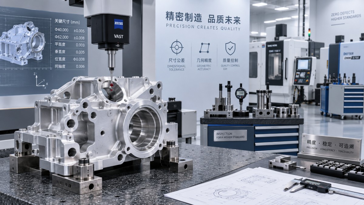
A diameter tolerance alone does not control where a hole is, whether it is perpendicular to a mounting face, or whether multiple holes form a usable pattern. Conversely, a very tight positional tolerance does not automatically ensure an appropriate fit if the feature size is poorly chosen.
Technical reviews should distinguish the controls by the function they protect.
The drawing should express the feature’s job, not merely describe its shape. A locating pin hole, for example, needs a size range compatible with the pin and a location requirement related to the surfaces that locate the assembled component. Treating either control as a substitute for the other often leads to inspection disputes and assembly variability.
Assign tolerance where the process can control it
Capability is not a property of “CNC machining” in the abstract. It depends on material condition, part rigidity, feature access, machine configuration, cutter reach, fixturing, tool wear, thermal behavior, finishing operations, and the measurement system.
A short, accessible bore in a stable aluminum part is a different manufacturing problem from a deep bore in a thin-walled stainless component. A tightly controlled datum face may be practical in one setup but difficult after the part is released and re-fixtured. Five-axis access can reduce some setup-related errors, yet it does not remove the effects of deflection, heat, vibration, or part distortion after material removal.
When reviewing a tolerance, ask which operation establishes it. Then ask whether that operation references the same datums used on the drawing. If the part is turned, milled, heat-treated, coated, and then inspected, the final tolerance must account for the change introduced at each stage. A requirement that is achievable before finishing may be unsuitable after coating growth, stress relief, or surface treatment.
Features that interact should also be considered together. Tightening the position of holes may demand a more stable primary datum. Tightening a bearing-seat diameter may require a corresponding decision about cylindricity, surface finish, shoulder perpendicularity, and post-process handling. Isolating one callout can create a false sense of control.
Cost rises at tolerance transitions, not only at tight values
The relationship between tolerance and cost is rarely a smooth line. A modest change may have little effect while the existing process remains capable. Crossing a process boundary can change the economics sharply: an ordinary milling operation may require a finishing pass; a finish pass may require a different fixture; a different fixture may require more setup time and additional inspection.
For this reason, a tolerance review should identify the process change triggered by the requirement. Questions worth asking include:
- Can the feature be completed in the same setup as its functional datums?
- Does the requirement need roughing and finishing as separate operations?
- Will a special tool, grinding, honing, lapping, or controlled environment be required?
- Does the measurement uncertainty consume a meaningful share of the specified band?
- Will inspection require a fixture, coordinate measurement program, functional gauge, or full reporting?
- Does the tolerance increase rejection risk because normal process drift has little room left?
The lowest unit machining price is also not always the lowest system cost. A broader tolerance that forces selective assembly, rework, or lengthy incoming inspection can be more expensive than a controlled feature made correctly at the source. The best limit minimizes total cost across machining, quality control, assembly, field reliability, and supplier management.
Measurement capability must be part of the specification
A tolerance cannot be managed if the measurement method produces ambiguous results. This issue becomes serious when the acceptable variation is close to the repeatability of the gauge, fixture, operator method, or environmental condition.
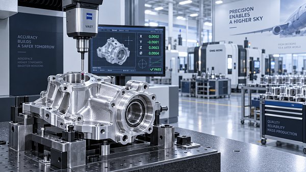
Technical evaluators should require agreement on how critical features will be verified before release to production. The inspection method must define the datum establishment, part restraint, probe or gauge access, sampling logic, reporting format, and treatment of temperature-sensitive measurements. A coordinate measuring machine can provide detailed data, but it is not automatically the best answer. A functional gauge may reflect the assembly condition more directly for high-volume interfaces, while in-process probing may help control a feature before it leaves the machine.
Measurement is especially important for geometric tolerances. Two teams can obtain different results from the same part if they establish datums differently or use incompatible filtering and evaluation practices. The drawing should therefore be clear enough that the intended functional interpretation is repeatable across the design, machining, and quality teams.
Use material condition and datum strategy deliberately
Material condition modifiers can be valuable when the function depends on a boundary rather than a fixed feature size. In appropriate applications, they allow a larger positional tolerance as a feature departs from its maximum material boundary, while preserving the functional assembly envelope. This can reduce unnecessary manufacturing difficulty without sacrificing fit.
They are not a universal cost-reduction device. Their use depends on the interface being genuinely governed by a material boundary and on inspection being able to verify the condition correctly. Applying modifiers to a feature because they provide more drawing tolerance, rather than because the function supports them, can make the specification harder to interpret and less reliable in use.
Datum selection deserves the same discipline. A datum feature should be stable, accessible, and functionally meaningful. Cosmetic faces, unfinished surfaces, thin flexible walls, and features that are not contacted in assembly are poor choices unless there is a clear reason. If a part is located in service by a bore and a mounting face, the tolerancing scheme should generally reflect that physical relationship.
Review common over-tolerancing patterns
Some drawing habits repeatedly add cost with limited functional value. Blanket tight general tolerances are a common example. They force attention onto dimensions that do not influence the part’s interface, while potentially obscuring the few features that truly drive performance.
Another pattern is dimensioning every feature from one arbitrary edge. This creates long tolerance chains and makes inspection less aligned with the assembly. Baseline or ordinate schemes can be more effective when they originate from functional datums, but only when the datum system itself matches how the part is located.
Calling out very tight profile tolerance across an entire complex part is also risky when only a few local surfaces matter. The supplier may need to inspect and control a large amount of geometry that has little product value. A better approach is to place stringent requirements on critical sealing, locating, or load-bearing regions and use reasonable general controls elsewhere.
Finally, do not confuse a narrow tolerance band with robust design. A design that only works at nominal dimensions is fragile. Robustness comes from preserving functional margin despite expected variation in parts, assembly, environment, and service load.
A release-ready tolerance review
Before releasing a machined component or assessing a supplier quotation, conduct a focused review of each critical interface. Confirm the functional requirement, mating-part limits, relevant stack, datum scheme, process route, inspection method, and failure consequence. Then challenge every unusually tight requirement: does it protect a defined risk, or does it simply express uncertainty?
For aerospace, medical-device, robotics, and high-reliability industrial work, traceability matters as much as the final number. Process capability evidence, first-article inspection, control plans, and revision discipline can be more informative than broad claims of precision. TSV’s engineering-benchmarking perspective is useful here: compare measurable process evidence and clearly defined limits, rather than relying on generic statements about manufacturing quality.
A toleranced drawing becomes commercially effective when design intent, process control, and verification all describe the same physical reality. That alignment is what allows a part to meet its function consistently without paying for precision that the product never uses.
Search News
Hot Articles
- Carbon Fiber StructuresHow to Specify Aerospace Carbon Fiber Assemblies for Lightweight, Load-Bearing PartsJul 11, 2026
- Machine VisionXiaomi, Alibaba DAMO Academy Drive Open-Source Robotics Model Ecosystem, Lowering Algorithm Development Barriers for Overseas SMEs Adopting Chinese Robotics SolutionsMar 30, 2026
- Cobots & ArmsShanxi 'AI+' Conference Showcases Embodied Intelligence with Multinational Buyer Engagement: Key Industry ImplicationsMar 30, 2026
Popular Tags
Recommended News
 Jul 11, 2026How to Specify Aerospace Carbon Fiber Assemblies for Lightweight, Load-Bearing PartsAerospace carbon fiber assemblies: learn how to specify laminate design, load data, joining methods, and inspection controls for lighter, reliable load-bearing aerospace parts.Elena Rostova (UAV Systems Researcher)
 Mar 30, 2026Xiaomi, Alibaba DAMO Academy Drive Open-Source Robotics Model Ecosystem, Lowering Algorithm Development Barriers for Overseas SMEs Adopting Chinese Robotics SolutionsXiaomi & Alibaba DAMO Academy's open-source robotics models lower algorithm barriers for global SMEs. Boost efficiency in manufacturing, logistics & smart retail with ROS 2 compatible solutions.TSV Data Lab
 Mar 30, 2026Shanxi 'AI+' Conference Showcases Embodied Intelligence with Multinational Buyer Engagement: Key Industry ImplicationsShanxi 'AI+' Conference highlights embodied intelligence with Tesla, Ubtech & Jiantao showcasing multimodal robotics. 40+ global buyers validated tech on-site, creating new B2B channels for industrial automation & AI solutions.Chen Wei (Automation Lead Engineer)
 Mar 30, 2026Zhongguancun Unveils 6G Integrated Sensing-Computing-Intelligence Platform to Empower Embodied Robots for Global Industrial ApplicationsZhongguancun's new 6G platform revolutionizes industrial robotics with <10ms latency, empowering global automotive, logistics & port automation. Discover how this tech boosts China's smart manufacturing exports.TSV Data Lab
 Mar 30, 2026Mech-Mind Tianjin Embodied Intelligence R&D and Production Base Goes Live, Cutting Delivery Time by 20%–30% for Global Customized AMR+Vision SolutionsMech-Mind's Tianjin AMR+Vision production base cuts delivery time by 20%-30% for欧美 & Latin American markets. Discover how this PLd-certified facility accelerates customized robotics solutions for smart manufacturing and logistics.Chen Wei (Automation Lead Engineer)
 Mar 30, 2026Boao Forum Reveals 'Co-evolution of Big and Small Brains' Trend in Humanoid Robots, China's Embodied Intelligence Accelerates Adaptation to Overseas Manufacturing Service ScenariosDiscover how China's humanoid robots, featuring 'Co-evolution of Big and Small Brains,' are revolutionizing global manufacturing. Learn about Embodied Tian Gong 3.0's ISO compliance and overseas deployment at Boao Forum 2026.Chen Wei (Automation Lead Engineer)
 Mar 30, 2026China Railway Industrial Secures Patent for Embodied Robotics in Material Handling, Boosting High-Precision Delivery Capabilities for Overseas Infrastructure and Manufacturing ProjectsChina Railway Industrial's new patent for embodied robotics in material handling boosts high-precision delivery for global infrastructure & manufacturing. Discover how this innovation enhances logistics accuracy in automotive, rail transit & EPC projects.Chen Wei (Automation Lead Engineer)
 Sep 26, 2026Machining Tolerance Analysis: How to Set Limits That Meet Function and Cost TargetsMachining tolerance analysis: learn how to set functional limits, control tolerance stacks, reduce inspection risk, and balance precision with production cost.Dr. Marcus Vance
 Sep 25, 2026How to Evaluate an Industrial Infrastructure Data Platform for Multi-Site OperationsIndustrial infrastructure data platform evaluation guide for multi-site operations: compare data quality, edge resilience, interoperability, governance, and scalable proof-of-value criteria.Victor Lin (Chief Software Architect)
 Sep 24, 2026How to Select Machine Vision Optics for Accurate Inspection at Different Working DistancesMachine vision optics selection guide for accurate inspection at every working distance. Compare FOV, pixel scale, DOF, distortion, lighting, and telecentric options.TSV Data Lab
 Sep 23, 2026How to Evaluate a Machine Vision System Integrator for High-Speed Inspection LinesChoose a machine vision system integrator with proven expertise in high-speed inspection, reliable reject timing, robust optics, and measurable acceptance criteria.TSV Data Lab
 Sep 25, 2026How a smart factory with Industrial IoT reduces production blind spotsDiscover how a smart factory with Industrial IoT turns real-time machine, quality, and workflow data into actionable insights that reduce production blind spots and delivery risks.Victor Lin (Chief Software Architect)
 Sep 24, 2026When does Industrial IoT make smart manufacturing easier to scale?Smart manufacturing Industrial IoT scales when trusted data, interoperable systems, and secure workflows turn connected assets into measurable gains.TSV Data Lab
 Sep 23, 2026What drives ultra-precision machining cost at 1-micron tolerance?Ultra precision machining cost per part at 1 micron tolerance depends on process, material, metrology, and yield. Learn how to compare quotes confidently.Dr. Marcus Vance
 Sep 22, 2026Drone Engine-T550CC Applications: Build the UAV Power System Around the MissionAn application guide for Drone Engine-T550CC integration, covering payload planning, airframe matching, cooling, fuel, vibration, test procedures, documentation, and service preparation.Elena Rostova (UAV Systems Researcher)
 Sep 22, 2026How to Evaluate Industrial Edge Computing Vendors for Factory DeploymentIndustrial edge computing vendor evaluation guide for factories: compare latency, protocol fit, reliability, security, and lifecycle support before deployment.TSV Data Lab
 Sep 21, 2026Drone Payload Integration: Matching Power, Data, and Center of Gravity for Reliable FlightsDrone payload integration made practical: balance power, data, center of gravity, and endurance to build safer, more reliable mission-ready flights.Elena Rostova (UAV Systems Researcher)
 Sep 20, 2026Autonomous Navigation Pricing: Cost Drivers and Budget Benchmarks for AMR ProjectsAutonomous navigation price explained: compare AMR cost drivers, software, sensors, integration, safety, and lifecycle budgets to build a scalable project plan.Chen Wei (Automation Lead Engineer)
 Sep 19, 2026How to Scope Automation Integration Services for Multi-System Factory ProjectsAutomation integration services: learn how to scope multi-system factory projects with clear workflows, interface contracts, safety boundaries, and acceptance criteria.Victor Lin (Chief Software Architect)
 Sep 18, 2026Selecting UAV Aerospace Structural Parts for Strength, Weight, and Fatigue LifeUAV aerospace structural parts guide: compare strength, weight, stiffness, fatigue life, joints, and traceability to select reliable flight-ready components.Elena Rostova (UAV Systems Researcher)
 Sep 17, 2026Selecting Commercial Drone Payloads for European Inspection ProjectsCommercial drone payloads Europe: learn how to select RGB, thermal and LiDAR systems for compliant, reliable inspection data and better project outcomes.Elena Rostova (UAV Systems Researcher)
 Sep 16, 2026Machining Tolerance Validation: How to Verify Critical Dimensions Before Production ReleaseMachining tolerance analysis validation: verify critical dimensions, measurement systems, process capability, and tolerance stacks before production release.Dr. Marcus Vance
 Sep 15, 2026AGV Tape Guidance vs Laser Navigation: Which Fits Your Warehouse Layout?AGV tape guidance comparison: discover how tape and laser navigation fit changing warehouse layouts, docking needs, floor conditions, maintenance, and route flexibility.Chen Wei (Automation Lead Engineer)
 Sep 14, 2026How Point Cloud Analytics Improves Asset Inspection Workflows Across GCC ProjectsPoint cloud analytics GCC helps project leaders improve asset inspections with accurate change detection, safer workflows, and faster maintenance decisions.TSV Data Lab