How to Evaluate a Machine Vision System Integrator for High-Speed Inspection Lines
Publication Date
author
A high-speed inspection line can look convincing in a controlled demonstration and still fail at production speed. The decisive question is not whether a machine vision system integrator can detect a defect in a static image. It is whether the complete system can make the correct decision, communicate it to the reject mechanism, preserve traceable evidence, and remain stable through normal production variation.
For project execution, the main risks are tightly connected: insufficient image quality creates false rejects; excessive processing latency shifts reject timing; unstable lighting changes inspection thresholds; incomplete mechanical integration turns a valid vision result into a missed reject. A credible integrator evaluates these dependencies as one engineered system rather than as a camera, software, and PLC package assembled near the end of the project.
Start with the inspection decision, not the camera specification
Before reviewing suppliers, define what the line must decide and what constitutes a production failure. “Inspect for defects” is not an adequate requirement. The specification should distinguish between critical defects that must never pass, cosmetic defects that may be subject to agreed limits, and process variations that should be logged without triggering rejection.
Each defect class needs a measurable definition. That can include minimum detectable size, contrast against the background, allowable position range, orientation, shape, print quality, fill level, seal condition, or presence of a component. It should also state whether the defect must be detected on every unit, within a statistically defined sampling plan, or only when a process alarm threshold is reached.
A capable integrator will challenge vague requirements early. If a scratch is visible to an operator under oblique light but invisible under the proposed diffuse illumination, the issue is not software sensitivity. It is an unresolved inspection condition. Similarly, a requirement to read a code on a curved, reflective, moving surface contains several separate engineering problems: optical distortion, glare control, motion blur, depth of field, decoding reliability, and line synchronization.
Ask prospective integrators to translate each inspection requirement into an inspection method. The response should identify the expected image feature, the selected lighting geometry, camera resolution, lens characteristics, triggering arrangement, image-processing logic, and reject action. This creates a traceable link between the quality requirement and the proposed architecture.
Throughput is a system-level calculation
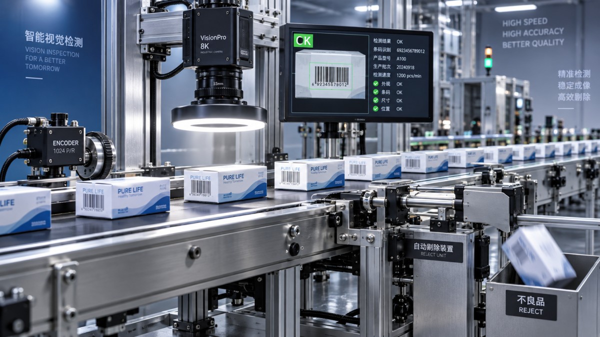
High-speed lines are often specified in units per minute, but vision performance must be assessed in distance and time. If product pitch is 150 mm and conveyor speed is 1.5 m/s, the interval between products is 100 milliseconds. Within that interval, the system may need to trigger an exposure, acquire an image, transfer data, process the image, send a result to the control system, and actuate a reject device at the correct downstream position.
These steps do not always occur sequentially; well-designed systems pipeline them. Even so, the total timing budget must be understood. The integrator should be able to document:
- maximum line speed, product spacing, and permitted speed variation;
- camera exposure time and the resulting motion blur at maximum speed;
- trigger-to-image acquisition delay and trigger repeatability;
- image transfer and processing latency under normal and peak load;
- PLC, industrial network, and output-response delay;
- distance from inspection point to reject point and reject-device response time;
- how the system handles products entering too closely, missing encoder counts, or missed triggers.
A statement such as “real-time processing” has little value without a defined maximum latency and a defined worst-case operating condition. The relevant figure is not the average inference or inspection time shown by a software dashboard. It is the upper-bound time from valid product trigger to available decision, including image acquisition and communications, while all required inspection stations are active.
Where product location is controlled by an encoder, evaluate how encoder pulses are acquired, filtered, and related to the reject queue. Where speed changes during operation, a fixed delay after image capture may be inadequate. The reject command may need position tracking rather than time tracking. For lines with frequent stops, starts, or accumulation behavior, the proposal should explain what happens to products already in the inspection-to-reject zone when the conveyor state changes.
Optics and lighting reveal whether the design is production-ready
Many inspection failures attributed to algorithms are actually imaging failures. The integrator should be able to explain why a particular lighting method makes the target defect distinguishable from acceptable product variation.
Diffuse dome or flat-field lighting can reduce reflections on curved or glossy surfaces. Low-angle dark-field lighting can make raised edges, scratches, and embossed features stand out. Backlighting is often appropriate for silhouette, dimensional, fill-level, or presence/absence checks. Coaxial illumination can be useful when viewing flat reflective surfaces through the same optical axis as the camera. None of these methods is universally superior; the correct choice depends on the physical feature being inspected.
Demand evidence that the proposed setup considers the production environment, not only laboratory samples. Relevant disturbances include ambient light from open guarding, vibration transmitted through frames, dust on protective windows, reflective changes caused by product moisture or surface treatment, and variation between incoming material lots. If the system depends on tightly controlled lighting, the enclosure, shielding, window maintenance, and illumination monitoring should be included in the scope.
Lens selection also deserves more scrutiny than it often receives. Standard lenses can introduce perspective or barrel distortion, especially near the image edge. Telecentric optics may be needed where dimensional measurement accuracy is sensitive to object distance or where the line must inspect parts with meaningful height variation. Depth of field must cover the actual movement range of the product, including belt runout, guide variation, and part tilt. A high-resolution camera does not create usable measurement accuracy if the image is blurred, distorted, poorly illuminated, or unstable from one cycle to the next.
Validate the detection claim with representative variation
The most useful supplier evaluation is a structured feasibility test using representative samples. This should include acceptable products across the expected manufacturing range, known defects near the detection limit, borderline samples, and variation caused by packaging, printing, material finish, or assembly position. A small set of ideal defects proves little about a system’s operating margin.
Test conditions should replicate the intended line as closely as practical: production speed, realistic orientation variation, operating distance, vibration, and surface condition. If those conditions cannot be reproduced before installation, the contract should clearly separate what has been demonstrated from what remains to be validated during site acceptance.
The evaluation should report more than a single accuracy percentage. At minimum, review the confusion between good and bad units:
- False accept: a defective unit classified as good. This is normally the highest quality risk.
- False reject: an acceptable unit classified as defective. This affects yield, operator workload, and confidence in automation.
- Inconclusive result: the system cannot make a valid decision because of image quality, positioning, communication, or another defined exception.
False rejects are not merely a nuisance. On a fast line, they can create reinspection queues, unnecessary scrap, or operators bypassing the vision system to maintain output. The integrator should state how inspection thresholds are established, who can change them, how changes are logged, and whether a threshold adjustment requires revalidation.
For measurement applications, review the complete measurement system rather than only pixel resolution. Calibration method, reference artifacts, mounting rigidity, thermal effects, lens distortion correction, part presentation, and repeatability all influence the usable result. A pixel-to-millimeter conversion shown during commissioning is not equivalent to demonstrated measurement capability over the required operating range.
Assess the architecture behind the inspection screen
A high-speed vision cell should be evaluated as an operational technology asset with defined interfaces and failure behavior. The proposed architecture should show cameras, lighting controllers, industrial PCs or smart cameras, network switches, PLC interfaces, encoder inputs, HMI functions, reject devices, and data storage. Ambiguity between the machine builder, controls contractor, and vision supplier is a common source of late-stage integration gaps.
Clarify the control logic for degraded conditions. If a camera disconnects, disk space is exhausted, a light source falls outside its expected output range, or an AI model service fails, does the line stop, divert all products, allow manual operation, or continue with inspection disabled? The answer depends on the criticality of the inspected characteristic, but it must be designed deliberately and accepted by the quality and operations functions.
Data retention needs similar discipline. Saving every full-resolution image may be valuable for investigations but can create storage, network, and retrieval burdens. A practical design may retain all failed images, periodic accepted-image samples, decision metadata, recipe version, operator changes, and system alarms, while storing full image sets only for a defined period. The retention policy should support root-cause analysis without quietly overwhelming the local computer or plant network.
If remote support, centralized monitoring, or connection to manufacturing systems is included, responsibility for network segmentation, account management, patching, and remote-access approval should be explicit. Industrial cybersecurity requirements vary by site and sector. Where an organization uses IEC 62443-based controls or comparable internal requirements, the integrator must show how the solution can fit the required zones, access rules, and asset-management process rather than treating the vision computer as an unmanaged exception.
Examine maintainability before approving the layout
Inspection performance gradually degrades when routine service is difficult. Camera mounts drift, lens windows collect contamination, lighting intensity changes over time, and product changeovers alter the inspection geometry. The proposed station should allow safe cleaning, repeatable camera adjustment, protected cable routing, and access to spare parts without disturbing calibrated components.
Ask how recipes are managed when the line handles multiple SKUs or formats. A recipe should control the relevant parameters—exposure, lighting settings, region of interest, tolerances, model version, reject timing, and product-specific geometry—without allowing uncontrolled edits. The system should identify the active recipe and prevent a product from running under the wrong inspection configuration where that creates a quality risk.
Training must cover more than HMI navigation. Site personnel need a defined method to distinguish a true defect trend from a vision-system issue, confirm that a reject action occurred, inspect failed images, perform cleaning and verification checks, and escalate faults with usable diagnostic information. The integrator’s documentation should include electrical drawings, network details, backup and restoration procedures, calibration instructions, spare-parts lists, and source or configuration ownership terms that match the buyer’s support model.
Use acceptance criteria that cannot be reinterpreted at handover
A project can become contentious when “successful commissioning” is left undefined. Factory acceptance testing and site acceptance testing should be tied to measurable conditions: product types, line speed, sample composition, required inspection functions, reject verification, alarm behavior, data capture, and allowed exception handling. If the system uses machine learning, the approved model version, training-data responsibility, retraining process, and performance requalification trigger should be documented.
Acceptance should also verify the full reject chain. A correct classification is not sufficient if the wrong product is ejected, a reject confirmation sensor is absent, or rejected units can re-enter the good-product stream. On tightly spaced products, testing must demonstrate that the reject mechanism does not affect adjacent units.
Commercial comparison should therefore look beyond initial hardware cost. A lower-priced proposal may exclude line-side mechanics, guarding modifications, electrical installation, sample testing, controls programming, data interfaces, commissioning support, or post-acceptance tuning. Compare scope boundaries, assumptions, exclusions, and change-control terms line by line. The cost of resolving an undefined interface during ramp-up is usually higher than clarifying it before purchase order release.
The strongest machine vision system integrator is not necessarily the one presenting the sharpest demo images or the broadest list of camera brands. It is the one that can convert a quality requirement into a quantified imaging, timing, controls, validation, and support design—and can identify the conditions under which that design will no longer be reliable. That discipline is what protects throughput, product quality, and project schedule when the inspection line moves from demonstration to continuous production.
Search News
Hot Articles
- Carbon Fiber StructuresHow to Specify Aerospace Carbon Fiber Assemblies for Lightweight, Load-Bearing PartsJul 11, 2026
- Machine VisionXiaomi, Alibaba DAMO Academy Drive Open-Source Robotics Model Ecosystem, Lowering Algorithm Development Barriers for Overseas SMEs Adopting Chinese Robotics SolutionsMar 30, 2026
- Cobots & ArmsShanxi 'AI+' Conference Showcases Embodied Intelligence with Multinational Buyer Engagement: Key Industry ImplicationsMar 30, 2026
Popular Tags
Recommended News
 Jul 11, 2026How to Specify Aerospace Carbon Fiber Assemblies for Lightweight, Load-Bearing PartsAerospace carbon fiber assemblies: learn how to specify laminate design, load data, joining methods, and inspection controls for lighter, reliable load-bearing aerospace parts.Elena Rostova (UAV Systems Researcher)
 Mar 30, 2026Xiaomi, Alibaba DAMO Academy Drive Open-Source Robotics Model Ecosystem, Lowering Algorithm Development Barriers for Overseas SMEs Adopting Chinese Robotics SolutionsXiaomi & Alibaba DAMO Academy's open-source robotics models lower algorithm barriers for global SMEs. Boost efficiency in manufacturing, logistics & smart retail with ROS 2 compatible solutions.TSV Data Lab
 Mar 30, 2026Shanxi 'AI+' Conference Showcases Embodied Intelligence with Multinational Buyer Engagement: Key Industry ImplicationsShanxi 'AI+' Conference highlights embodied intelligence with Tesla, Ubtech & Jiantao showcasing multimodal robotics. 40+ global buyers validated tech on-site, creating new B2B channels for industrial automation & AI solutions.Chen Wei (Automation Lead Engineer)
 Mar 30, 2026Zhongguancun Unveils 6G Integrated Sensing-Computing-Intelligence Platform to Empower Embodied Robots for Global Industrial ApplicationsZhongguancun's new 6G platform revolutionizes industrial robotics with <10ms latency, empowering global automotive, logistics & port automation. Discover how this tech boosts China's smart manufacturing exports.TSV Data Lab
 Mar 30, 2026Mech-Mind Tianjin Embodied Intelligence R&D and Production Base Goes Live, Cutting Delivery Time by 20%–30% for Global Customized AMR+Vision SolutionsMech-Mind's Tianjin AMR+Vision production base cuts delivery time by 20%-30% for欧美 & Latin American markets. Discover how this PLd-certified facility accelerates customized robotics solutions for smart manufacturing and logistics.Chen Wei (Automation Lead Engineer)
 Mar 30, 2026Boao Forum Reveals 'Co-evolution of Big and Small Brains' Trend in Humanoid Robots, China's Embodied Intelligence Accelerates Adaptation to Overseas Manufacturing Service ScenariosDiscover how China's humanoid robots, featuring 'Co-evolution of Big and Small Brains,' are revolutionizing global manufacturing. Learn about Embodied Tian Gong 3.0's ISO compliance and overseas deployment at Boao Forum 2026.Chen Wei (Automation Lead Engineer)
 Mar 30, 2026China Railway Industrial Secures Patent for Embodied Robotics in Material Handling, Boosting High-Precision Delivery Capabilities for Overseas Infrastructure and Manufacturing ProjectsChina Railway Industrial's new patent for embodied robotics in material handling boosts high-precision delivery for global infrastructure & manufacturing. Discover how this innovation enhances logistics accuracy in automotive, rail transit & EPC projects.Chen Wei (Automation Lead Engineer)
 Sep 23, 2026How to Evaluate a Machine Vision System Integrator for High-Speed Inspection LinesChoose a machine vision system integrator with proven expertise in high-speed inspection, reliable reject timing, robust optics, and measurable acceptance criteria.TSV Data Lab
 Sep 23, 2026What drives ultra-precision machining cost at 1-micron tolerance?Ultra precision machining cost per part at 1 micron tolerance depends on process, material, metrology, and yield. Learn how to compare quotes confidently.Dr. Marcus Vance
 Sep 22, 2026Drone Engine-T550CC Applications: Build the UAV Power System Around the MissionAn application guide for Drone Engine-T550CC integration, covering payload planning, airframe matching, cooling, fuel, vibration, test procedures, documentation, and service preparation.Elena Rostova (UAV Systems Researcher)
 Sep 22, 2026How to Evaluate Industrial Edge Computing Vendors for Factory DeploymentIndustrial edge computing vendor evaluation guide for factories: compare latency, protocol fit, reliability, security, and lifecycle support before deployment.TSV Data Lab
 Sep 21, 2026Drone Payload Integration: Matching Power, Data, and Center of Gravity for Reliable FlightsDrone payload integration made practical: balance power, data, center of gravity, and endurance to build safer, more reliable mission-ready flights.Elena Rostova (UAV Systems Researcher)
 Sep 20, 2026Autonomous Navigation Pricing: Cost Drivers and Budget Benchmarks for AMR ProjectsAutonomous navigation price explained: compare AMR cost drivers, software, sensors, integration, safety, and lifecycle budgets to build a scalable project plan.Chen Wei (Automation Lead Engineer)
 Sep 19, 2026How to Scope Automation Integration Services for Multi-System Factory ProjectsAutomation integration services: learn how to scope multi-system factory projects with clear workflows, interface contracts, safety boundaries, and acceptance criteria.Victor Lin (Chief Software Architect)
 Sep 18, 2026Selecting UAV Aerospace Structural Parts for Strength, Weight, and Fatigue LifeUAV aerospace structural parts guide: compare strength, weight, stiffness, fatigue life, joints, and traceability to select reliable flight-ready components.Elena Rostova (UAV Systems Researcher)
 Sep 17, 2026Selecting Commercial Drone Payloads for European Inspection ProjectsCommercial drone payloads Europe: learn how to select RGB, thermal and LiDAR systems for compliant, reliable inspection data and better project outcomes.Elena Rostova (UAV Systems Researcher)
 Sep 16, 2026Machining Tolerance Validation: How to Verify Critical Dimensions Before Production ReleaseMachining tolerance analysis validation: verify critical dimensions, measurement systems, process capability, and tolerance stacks before production release.Dr. Marcus Vance
 Sep 15, 2026AGV Tape Guidance vs Laser Navigation: Which Fits Your Warehouse Layout?AGV tape guidance comparison: discover how tape and laser navigation fit changing warehouse layouts, docking needs, floor conditions, maintenance, and route flexibility.Chen Wei (Automation Lead Engineer)
 Sep 14, 2026How Point Cloud Analytics Improves Asset Inspection Workflows Across GCC ProjectsPoint cloud analytics GCC helps project leaders improve asset inspections with accurate change detection, safer workflows, and faster maintenance decisions.TSV Data Lab
 Sep 13, 2026How Aerospace Manufacturers Can Build a Digital Thread From Design to Certified ProductionDigital manufacturing for aerospace: learn how to build a traceable digital thread from design through certified production, supplier control, and audit-ready compliance.Victor Lin (Chief Software Architect)
 Sep 12, 2026How to Select a Thermal Sensor for Mapping Drones in Surveying ProjectsMapping drone thermal sensor selection made simple: compare GSD, radiometric data, NETD, calibration, and workflow fit for accurate, survey-ready thermal maps.Elena Rostova (UAV Systems Researcher)
 Sep 11, 2026Integrating Photogrammetry Workflows into Digital Twin Projects Without Data BottlenecksPhotogrammetry workflow integration for digital twins: learn how to streamline capture, validation, versioning, and delivery to prevent data bottlenecks.Victor Lin (Chief Software Architect)
 Sep 10, 2026Hard-Tech Supply Chain Procurement: Qualifying Suppliers to Cut Lead-Time RiskHard-tech supply chain procurement guide: qualify suppliers with proven process, traceability, capacity, and change control to reduce lead-time risk.Chen Wei (Automation Lead Engineer)
 Sep 09, 2026Industrial Application Notes: Cost Factors That Shape Automation Project BudgetsIndustrial application notes cost factors explained: uncover the engineering, safety, integration, and commissioning variables that shape accurate automation budgets.Victor Lin (Chief Software Architect)