ToF camera depth accuracy in millimeters depends on surface type
Publication Date
author
When engineers ask whether ToF camera depth accuracy in millimeters is truly achievable, the practical answer is yes—but only under controlled conditions, and surface type is one of the biggest reasons lab performance fails to match production reality. Glossy plastics, dark rubber, brushed metal, transparent films, and angled parts can all distort depth readings in different ways. For R&D teams, operators, procurement specialists, and decision-makers, the real question is not whether a vendor claims millimeter accuracy, but on which surfaces, at what distance, under what lighting, and with what failure rate. That is the level of detail that matters when selecting and validating a ToF camera for robotics, industrial inspection, logistics, and edge AI deployments.
Why surface type changes ToF camera depth accuracy more than many buyers expect
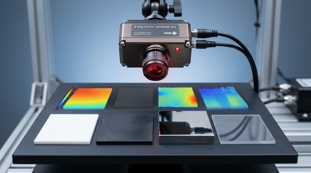
A time-of-flight camera measures distance by emitting light and calculating how long that light takes to return. In theory, this sounds straightforward. In practice, the returning signal is shaped by the object surface before the sensor ever calculates depth. That is why ToF camera depth accuracy in millimeters depends on surface type far more than many specification sheets suggest.
The main issue is that different materials reflect or scatter light differently:
- Matte, bright, diffuse surfaces usually produce the most stable depth results.
- Dark surfaces absorb more light, reducing signal strength and increasing noise.
- Glossy or specular surfaces can reflect light away from the sensor or create misleading returns.
- Transparent or translucent materials may transmit or scatter light through the material rather than from the true outer surface.
- Textured surfaces can improve or destabilize measurement depending on pattern scale and lighting interaction.
- Steep surface angles often weaken the return signal and increase error at edges.
For users comparing systems, this means a vendor’s “±1 mm” or “millimeter-level” claim is incomplete unless it is tied to a specific target type, working distance, field of view, integration time, ambient light condition, and confidence threshold.
What engineers, operators, and buyers actually need to know before trusting millimeter claims
Most target readers are not looking for a basic textbook explanation of ToF. They want to know whether the camera will work on their parts, in their line, with their throughput constraints. The most useful way to evaluate depth performance is to focus on a few operational questions.
- What material is being measured? Painted metal, black polymer, PCB surfaces, composite panels, and packaged goods behave differently.
- At what distance is millimeter accuracy required? A sensor may perform well at 300 mm and degrade sharply at 1,500 mm.
- Is the measurement static or dynamic? Motion introduces exposure tradeoffs and multipath artifacts.
- What are the lighting conditions? Sunlight, factory lighting, and reflective surroundings can reduce stability.
- Is the application looking at flat planes, edges, holes, or mixed materials? Edge transitions are often where depth errors become unacceptable.
- What is the acceptable failure mode? Is occasional noise acceptable, or does the process require deterministic pass/fail measurement?
For procurement teams and decision-makers, the key takeaway is simple: do not buy on headline accuracy alone. Buy on validated accuracy for your actual surface set.
How different surface types affect real-world ToF depth results
Below is the practical behavior many teams see during evaluation and deployment.
1. Matte white or light gray surfaces
These are generally the easiest targets for ToF systems. They provide strong diffuse reflection and usually support the best signal-to-noise ratio. If a supplier reports excellent millimeter performance, there is a good chance the test target looked like this.
2. Black rubber, dark plastics, and low-reflectivity coatings
These surfaces absorb more emitted light, so the return signal is weaker. The result can be noisier depth maps, more missing pixels, and lower repeatability. In automation systems, this often shows up as unstable edge detection, fluctuating height values, or reduced confidence under faster cycle times.
3. Glossy metal, polished parts, and reflective packaging
Specular reflection is one of the biggest causes of unexpected depth error. The reflected light may bounce away from the sensor, saturate certain areas, or create multipath effects from surrounding structures. This can produce false depth, holes in the point map, or unreliable measurement near corners and curved features.
4. Transparent films, glass, and translucent materials
These are difficult for most ToF systems because the emitted light may partially pass through the material, reflect from internal layers, or scatter unpredictably. If the application involves bottles, protective covers, films, adhesives, or glass components, a ToF camera may need careful filtering, angle control, or even a different sensing method altogether.
5. Rough or textured industrial surfaces
Texture can help by breaking up specular highlights, but it can also create local depth variation if the texture scale is large relative to the required tolerance. Cast parts, woven composites, machined surfaces, and powder-coated finishes should be tested directly, not approximated from a “similar” sample.
6. Angled surfaces and edge regions
Even on otherwise cooperative materials, depth accuracy often degrades as the angle increases. At edges, mixed pixels and reduced return strength can cause systematic error. If the use case involves bin picking, pallet profiling, pose estimation, or part alignment, angle-dependent testing is mandatory.
Why lab accuracy and factory accuracy are often not the same
The gap between brochure performance and deployment performance usually comes from test conditions that are too favorable. A camera can achieve excellent depth precision in a controlled bench setup with:
- short fixed working distance
- matte calibration target
- stable temperature
- minimal ambient light
- longer integration time
- static object positioning
Production environments are rarely that forgiving. Real installations introduce conveyor motion, mixed surfaces, vibration, changing illumination, thermal drift, contamination, and parts that are not always presented at the ideal angle. For this reason, teams should separate three different performance concepts:
- Resolution: how many depth pixels the sensor provides.
- Precision: how repeatable the measurement is under the same condition.
- Accuracy: how close the measurement is to the true physical distance.
A ToF camera can have high resolution and decent repeatability while still missing true millimeter-level accuracy on difficult surfaces.
How to validate whether millimeter-level ToF depth accuracy is realistic for your application
For R&D teams and technical buyers, the best approach is a structured validation plan rather than a single demo. A practical evaluation should include:
- Build a surface matrix. Test all relevant materials: dark, bright, glossy, matte, coated, transparent, and worn production samples.
- Test across the full distance range. Do not validate only at the ideal midpoint.
- Measure flatness, edges, and angled targets. Many systems pass flat-target tests but fail at geometry transitions.
- Evaluate repeatability over time. Run short-term and long-duration trials to expose drift.
- Include ambient light variation. If the system will operate near windows, skylights, or strong LEDs, test those conditions.
- Quantify invalid-pixel rate. Missing or low-confidence data matters as much as average error.
- Compare against a reference instrument. Use a calibrated gauge, CMM, laser profiler, or certified target setup.
Most importantly, record results by surface type + distance + angle + exposure setting + error distribution. That creates decision-grade data instead of anecdotal impressions.
When ToF is the right choice—and when another depth technology may be better
ToF cameras are often an excellent choice when users need compact depth sensing, real-time output, broad-area coverage, and reasonable integration cost. They are particularly useful in robotics, occupancy measurement, pallet dimensioning, gesture sensing, and general 3D scene understanding.
However, if the application requires highly consistent sub-millimeter or tightly bounded millimeter accuracy on difficult surfaces, another technology may be more suitable, such as:
- Laser triangulation for high-precision profile measurement
- Structured light for detailed surface reconstruction in controlled environments
- Confocal or chromatic sensing for demanding precision metrology
- Industrial 3D line scanners for moving inspection tasks with challenging tolerances
For decision-makers, this is a business issue as much as a technical one. Choosing an underqualified ToF sensor can lead to integration delays, false rejects, lower throughput, or expensive redesigns. Choosing an overqualified metrology system can inflate cost and complexity unnecessarily. The right decision depends on matching the surface physics to the measurement requirement.
What to ask a ToF camera supplier before shortlisting a sensor
If a vendor claims millimeter performance, ask for evidence in terms that matter operationally:
- On which exact surface types was the accuracy measured?
- At what working distances and incidence angles?
- What was the ambient light condition?
- What percentage of pixels were invalid or low confidence?
- How was ground truth established?
- What was the repeatability over 8-hour or 24-hour tests?
- How does performance change on black, reflective, and transparent targets?
- Is there application data from similar industries or part materials?
These questions help buyers filter out marketing language and focus on engineering truth—especially important when the sensor will influence production quality, robot guidance reliability, or inspection yield.
Conclusion: millimeter-level ToF depth accuracy is possible, but only when surface behavior is treated as a first-order design variable
The core answer is clear: ToF camera depth accuracy in millimeters depends on surface type, and that dependency is strong enough to make or break an application. Matte diffuse targets may support excellent performance, while dark, reflective, transparent, or sharply angled surfaces can introduce significant error, noise, or data loss.
For engineers and operators, the practical priority is validation on real parts, not ideal samples. For procurement teams, the right buying standard is evidence by material class and operating condition, not generic accuracy claims. For business decision-makers, the strategic takeaway is that depth sensing performance should be qualified against deployment risk, rework cost, and process tolerance—not brochure language.
If millimeter accuracy matters, surface-aware testing is not optional. It is the baseline for making a sound technical and commercial decision.
Search News
Hot Articles
- Carbon Fiber StructuresHow to Specify Aerospace Carbon Fiber Assemblies for Lightweight, Load-Bearing PartsJul 11, 2026
- Machine VisionXiaomi, Alibaba DAMO Academy Drive Open-Source Robotics Model Ecosystem, Lowering Algorithm Development Barriers for Overseas SMEs Adopting Chinese Robotics SolutionsMar 30, 2026
- Cobots & ArmsShanxi 'AI+' Conference Showcases Embodied Intelligence with Multinational Buyer Engagement: Key Industry ImplicationsMar 30, 2026
Popular Tags
Recommended News
 Jul 11, 2026How to Specify Aerospace Carbon Fiber Assemblies for Lightweight, Load-Bearing PartsAerospace carbon fiber assemblies: learn how to specify laminate design, load data, joining methods, and inspection controls for lighter, reliable load-bearing aerospace parts.Elena Rostova (UAV Systems Researcher)
 Mar 30, 2026Xiaomi, Alibaba DAMO Academy Drive Open-Source Robotics Model Ecosystem, Lowering Algorithm Development Barriers for Overseas SMEs Adopting Chinese Robotics SolutionsXiaomi & Alibaba DAMO Academy's open-source robotics models lower algorithm barriers for global SMEs. Boost efficiency in manufacturing, logistics & smart retail with ROS 2 compatible solutions.TSV Data Lab
 Mar 30, 2026Shanxi 'AI+' Conference Showcases Embodied Intelligence with Multinational Buyer Engagement: Key Industry ImplicationsShanxi 'AI+' Conference highlights embodied intelligence with Tesla, Ubtech & Jiantao showcasing multimodal robotics. 40+ global buyers validated tech on-site, creating new B2B channels for industrial automation & AI solutions.Chen Wei (Automation Lead Engineer)
 Mar 30, 2026Zhongguancun Unveils 6G Integrated Sensing-Computing-Intelligence Platform to Empower Embodied Robots for Global Industrial ApplicationsZhongguancun's new 6G platform revolutionizes industrial robotics with <10ms latency, empowering global automotive, logistics & port automation. Discover how this tech boosts China's smart manufacturing exports.TSV Data Lab
 Mar 30, 2026Mech-Mind Tianjin Embodied Intelligence R&D and Production Base Goes Live, Cutting Delivery Time by 20%–30% for Global Customized AMR+Vision SolutionsMech-Mind's Tianjin AMR+Vision production base cuts delivery time by 20%-30% for欧美 & Latin American markets. Discover how this PLd-certified facility accelerates customized robotics solutions for smart manufacturing and logistics.Chen Wei (Automation Lead Engineer)
 Mar 30, 2026Boao Forum Reveals 'Co-evolution of Big and Small Brains' Trend in Humanoid Robots, China's Embodied Intelligence Accelerates Adaptation to Overseas Manufacturing Service ScenariosDiscover how China's humanoid robots, featuring 'Co-evolution of Big and Small Brains,' are revolutionizing global manufacturing. Learn about Embodied Tian Gong 3.0's ISO compliance and overseas deployment at Boao Forum 2026.Chen Wei (Automation Lead Engineer)
 Mar 30, 2026China Railway Industrial Secures Patent for Embodied Robotics in Material Handling, Boosting High-Precision Delivery Capabilities for Overseas Infrastructure and Manufacturing ProjectsChina Railway Industrial's new patent for embodied robotics in material handling boosts high-precision delivery for global infrastructure & manufacturing. Discover how this innovation enhances logistics accuracy in automotive, rail transit & EPC projects.Chen Wei (Automation Lead Engineer)
 Oct 21, 2026China’s Industrial Robot Exports Near RMB 10 Billion in First Nine Months of 2026China’s industrial robot exports neared RMB 10 billion in January–September 2026, with value rising faster than volume. Explore the data and what it could mean for suppliers.Chen Wei (Automation Lead Engineer)
 Oct 21, 2026Low-Latency Industrial Data Processing: Pricing and Key Cost DriversExplore industrial data latency price drivers, from edge hardware to integration and support. Learn how to compare quotes, verify performance, and avoid unnecessary costs.TSV Data Lab
 Oct 20, 2026KUKA Launches iiQKA.AI Vision to Simplify Industrial Image ProcessingKUKA iiQKA.AI Vision simplifies industrial image processing with controller-based 2D and 3D vision. Explore drag-and-drop setup for vision-guided automation.TSV Data Lab
 Oct 20, 2026Smart Industrial Edge Devices: Key Criteria for Legacy PLC IntegrationChoose smart industrial edge devices for legacy PLC integration. Discover key criteria for compatibility, data quality, security, and reliable collection without disrupting control.TSV Data Lab
 Oct 19, 2026Choosing a Radar Sensor by Application: Range, Resolution, and Field of ViewSimplify radar sensor application based product selection. Compare range, resolution, and field of view to avoid blind spots and choose with confidence. Explore the guide.TSV Data Lab
 Oct 18, 2026Comparing Material Options for Procurement: Specs, Costs, and Supply RisksExplore procurement oriented technical content on material options, specs, costs, and supply risks. Compare alternatives to cut hidden expenses and make confident sourcing decisions.Dr. Marcus Vance
 Oct 17, 20265-Axis CNC Positioning Accuracy: How to Interpret ISO 230-2 Test ResultsAssess 5 axis CNC machining positioning accuracy with ISO 230-2. Learn to interpret repeatability, reversal error, and test conditions to compare suppliers and make confident acceptance decisions.Dr. Marcus Vance
 Oct 16, 2026Choosing a Rugged Edge AI Box Supplier: Thermal Tests and Lifecycle SupportChoose a rugged edge AI box supplier with proven thermal performance and reliable lifecycle support. Discover the tests and commitments to verify before you buy.TSV Data Lab
 Oct 15, 2026R&D Cost Reduction Services: How to Evaluate Fees, Savings, and ROIEvaluate R&D cost reduction services with confidence. Compare fees, verify savings, and calculate ROI without compromising performance. Discover how to choose a provider that delivers real value.Chen Wei (Automation Lead Engineer)
 Oct 21, 2026How Should You Balance Cobot Payload Against Reach?Explore cobot payload versus reach to choose the right robot. Learn how tooling, load limits, workspace, and cycle time affect performance—and avoid costly selection mistakes.Chen Wei (Automation Lead Engineer)
 Oct 20, 2026How Do You Measure Industrial IoT Gateway Latency Under Load?Measure industrial IoT gateway latency under load with reliable timestamps, realistic traffic, and tail-latency analysis. Discover how to expose bottlenecks and choose the right gateway.TSV Data Lab
 Oct 19, 2026How Do You Verify That Precision Machined Parts Meet Tolerances?Master precision machining tolerance verification with the right tools, datum setups, and acceptance rules. Learn how to validate parts confidently and reduce costly inspection errors.Dr. Marcus Vance
 Oct 18, 2026What Should an AS9100 Machining Supplier Checklist Include?Build an AS9100 machining supplier checklist that verifies capability, traceability, inspection, and outsourced processes. Discover what to check before approving your next aerospace supplier.Dr. Marcus Vance
 Oct 17, 2026How Should You Interpret Industrial Robot Repeatability Specs?Decode industrial robot repeatability specifications, understand ISO 9283 test conditions, and avoid costly selection mistakes. Learn how to verify performance for your process.Chen Wei (Automation Lead Engineer)
 Oct 16, 2026How Can You Fairly Compare MTBF Across Industrial Servo Motors?Make a fair industrial servo motor MTBF comparison with matched operating profiles, failure criteria, and confidence bounds. Discover how to assess reliability beyond advertised numbers.Chen Wei (Automation Lead Engineer)
 Oct 15, 2026How Should You Compare TechStat Vanguard 5-Axis CNC Tolerances?TechStat Vanguard 5-axis CNC tolerance comparison: learn how to verify part accuracy, assess inspection evidence, and choose suppliers that reliably meet your drawing requirements.Dr. Marcus Vance
 Oct 14, 2026Drone Frame Composites: Carbon Fiber vs. Fiberglass for Weight and StiffnessExplore drone structural materials composites: compare carbon fiber and fiberglass for weight, stiffness, cost, and antenna compatibility. Find the right material for your drone frame.Elena Rostova (UAV Systems Researcher)