Drone Frame Composites: Carbon Fiber vs. Fiberglass for Weight and Stiffness
Publication Date
author
Carbon fiber is generally the stronger choice when a drone frame must resist bending and twisting with limited structural mass. Fiberglass becomes attractive when the frame can tolerate additional weight or a larger section, and when material cost, electrical insulation, or radio-frequency transparency carries substantial value. The useful comparison is the mass required to meet a defined stiffness requirement—not simply the weight of two frames with different dimensions.
That distinction matters because a lightweight frame can still be too flexible for its motors, payload, or flight-control system. A heavier fiberglass structure may meet the same requirement through thicker walls or deeper sections. Conversely, a carbon frame can lose much of its expected advantage through unsuitable fiber orientation, flexible joints, or poor manufacturing quality. Material selection should begin with the frame’s load path and acceptable movement, then test which construction meets those limits.
Compare stiffness at a defined mass and geometry
For drone structural materials, composites should be evaluated as complete laminates. The stiffness of the reinforcement alone does not describe the stiffness of a finished arm or center plate. Fiber direction, fiber content, resin properties, voids, and the arrangement of layers all influence the result. A supplier’s fiber tensile-strength figure cannot establish how far an assembled motor mount will deflect under thrust.
Carbon reinforcement generally provides higher stiffness along the fiber direction than conventional glass reinforcement. Carbon-fiber composites also generally have lower density than comparable glass-fiber composites using similar resin systems and fiber fractions. Together, these characteristics give carbon a useful advantage in specific stiffness: stiffness relative to material density.
However, specific stiffness does not translate directly into a fixed percentage of frame-weight reduction. The answer depends on what the design holds constant. Three comparisons lead to different conclusions:
- Same geometry: With comparable laminate construction, carbon will generally produce a lighter, stiffer component. This comparison is useful when packaging dimensions are fixed.
- Same component mass: Fiberglass can use more material volume, potentially allowing thicker walls or a deeper section. The resulting stiffness depends on where that material sits.
- Same required stiffness: Each material should be sized independently, with both designs checked for strength, joints, damage tolerance, and manufacturing limits.
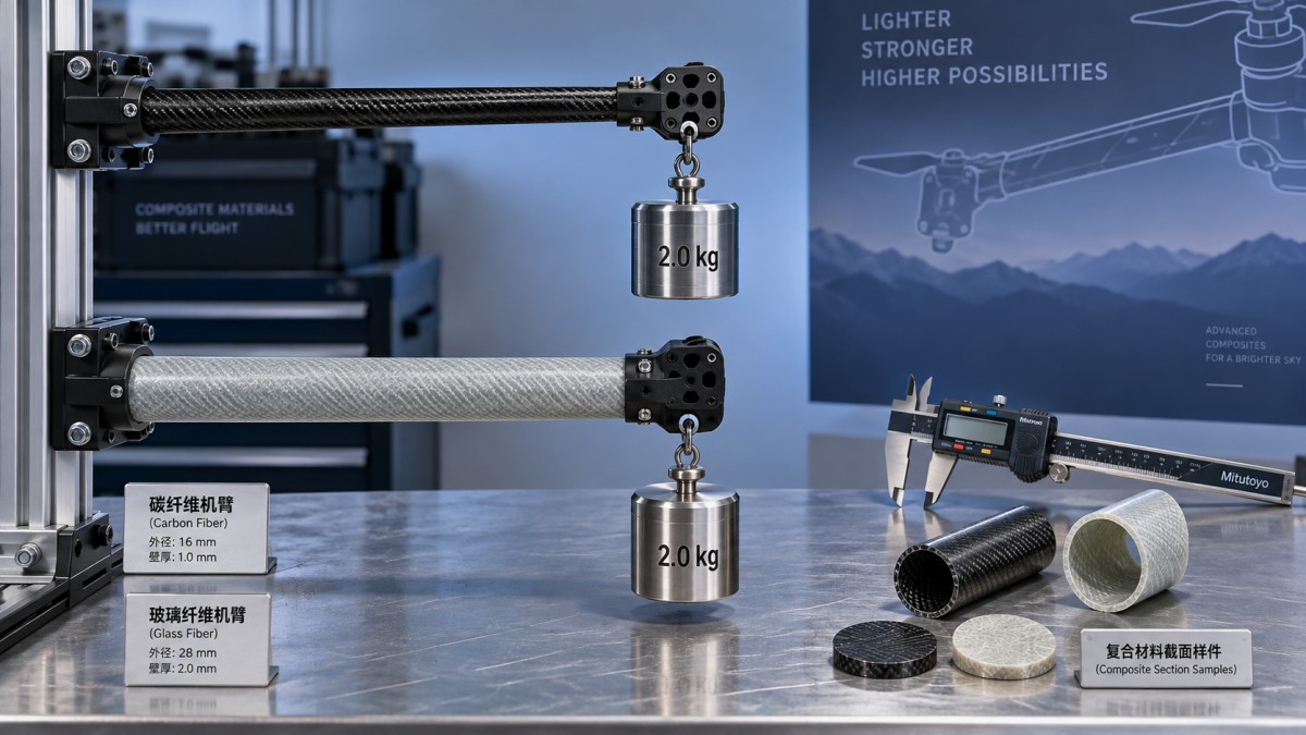
For a simple beam, bending stiffness depends on both elastic modulus and the second moment of area of its cross-section. Increasing section depth can substantially increase bending resistance. A fiberglass tube with a larger outside diameter may therefore compete with a smaller carbon tube, provided the larger tube fits the aircraft and its wall remains suitable for local loads.
Flat plates illustrate why equal-mass comparisons need care. In a simplified, geometrically similar plate comparison, bending stiffness rises strongly with thickness. Extra thickness can partly offset fiberglass’s lower modulus. An actual laminate requires directional bending properties, however, and a plate that resists vertical bending may still perform poorly under torsion or around fastener holes.
The practical starting point is to establish the available structural envelope. If arm diameter, plate thickness, folding clearance, or motor-mount height is tightly constrained, carbon’s material advantage becomes more valuable. If section dimensions can grow, fiberglass deserves a geometry-specific comparison before it is excluded on weight grounds.
Fiber placement and connections determine usable stiffness
A drone arm carries more than a vertical thrust load. Depending on the configuration, it must resist motor torque, lateral forces, maneuver loads, vibration, and handling or landing events. Longitudinal fibers contribute strongly to bending stiffness along the arm. Angled fibers help carry shear and torsion, while transverse reinforcement supports crosswise loads and local structural integrity.
A laminate dominated by longitudinal carbon fibers can look impressive in a bending calculation yet remain inadequate in torsion or at its attachment points. Adding fibers in other directions reduces the proportion available for longitudinal stiffness, but it can improve the performance of the complete component. A balanced woven plate is therefore not interchangeable with a predominantly unidirectional tube, even when both are sold as “carbon fiber.”
Request the reinforcement form and stacking sequence when evaluating candidate parts. The comparison should distinguish woven fabric, unidirectional reinforcement, and other constructions. A visible carbon weave establishes little about the layers beneath it. Likewise, a fiberglass part with a well-designed laminate can outperform a poorly specified carbon part in a particular load case without overturning carbon’s underlying specific-stiffness advantage.
The center-frame connection often limits how much of the arm’s stiffness reaches the assembled aircraft. Clamp slip, bolt clearance, local plate bending, and compliant inserts can allow motor movement even when the arm itself is sufficiently rigid. Reinforcing the arm further may add cost without meaningfully reducing that movement.
Measure displacement at the motor mount with the arm attached to a representative center structure. Include the intended fasteners, tightening procedure, inserts, and interface materials. This captures connection compliance that a coupon test or isolated-arm calculation misses. For folding frames, the hinge and locking mechanism belong in the same measurement.
Fastener regions also impose limits on weight reduction. Composite laminates can fail through bearing damage, splitting, delamination, or fastener pull-through. Thin carbon sections may need additional plies, load-spreading features, or inserts at these locations. Include those additions in the mass comparison, along with adhesive and attachment hardware.
Static deflection is only part of the flight requirement
A stiff frame can still transmit troublesome vibration if a structural mode is excited within the operating range. Natural frequencies depend on stiffness, mass distribution, and boundary conditions. Motors, batteries, landing gear, and payload mounts can change the response enough that testing an empty frame gives a misleading picture.
Higher stiffness generally raises a structure’s natural frequency when mass and boundary conditions remain fixed. Changing from fiberglass to carbon also changes mass, and redesigning the section changes both. The resulting modal behavior should be measured or modeled for the assembled configuration rather than inferred from material names.
Damping deserves separate attention. Resin selection, interfaces, mounting details, and laminate architecture affect how vibration decays. Claims that fiberglass always damps better, or that carbon always produces cleaner sensor data, are too broad to guide a purchase. Evaluate vibration at the flight controller and payload locations under representative excitation. For an imaging aircraft, motor-mount rigidity and camera-mount behavior may impose different requirements.
Where fiberglass remains a credible choice
Fiberglass is a reasonable candidate when its required thickness and mass fit comfortably within the aircraft’s limits. Protective frames, covers with modest structural duties, and components with generous section depth can offer more design freedom than long, slender motor arms. In those cases, paying for carbon may produce little operational value if fiberglass already meets the displacement and vibration requirements.
Glass reinforcement can also support electrical insulation and antenna integration. Carbon-fiber composites are electrically conductive and can affect antenna performance through shielding, absorption, or changes to the antenna’s electromagnetic environment. Fiberglass is generally more suitable for structures near antennas, although its resin, thickness, moisture condition, coatings, and fillers still affect radio-frequency behavior. Verify performance with the actual antenna placement and frequency band.
These differences can justify a mixed-material frame. Carbon arms may carry the primary flight loads while fiberglass serves in antenna covers or selected insulating interfaces. Hybrid construction adds interfaces and assembly work, so its value depends on whether those functions are significant enough to justify the complexity.
Contact with metal requires attention as well. Conductive carbon can contribute to galvanic corrosion when coupled to susceptible metals in the presence of an electrolyte. Appropriate isolation and sealing are relevant for exposed assemblies. Fiberglass can help provide electrical separation, but a nominal insulating layer is only effective if fasteners, edges, and damaged areas do not bypass it.
Glass reinforcement generally offers a lower material-cost starting point than carbon reinforcement. Finished-part cost still depends on tooling, layup labor, curing, machining, inspection, and rejection rates. A thicker fiberglass design may consume more material or require different hardware. Compare the cost of acceptable, finished assemblies, including any mass-related effect on payload capacity or endurance.
Neither material has a universal advantage after an impact. Damage depends on impact energy, laminate construction, support conditions, and the location of the strike. Carbon’s high stiffness does not guarantee damage tolerance, while fiberglass’s greater deformation capacity does not guarantee continued serviceability. Surface appearance alone may miss internal separation between layers.
Turn the comparison into an acceptance test
A useful specification gives suppliers a measurable component requirement. “High-strength carbon frame” leaves too much undefined. State the geometry constraints, installed mass limit, load cases, allowable deflection, and relevant environmental conditions. Identify where displacement is measured and how the part is supported. For a motor arm, include bending and torsional loading where both affect operation.
Separate normal-operation stiffness from structural survival. A frame may remain intact under a load while moving too far to preserve motor alignment or payload stability. It may also satisfy a static deflection limit but develop local damage after repeated loading. Each requirement needs evidence appropriate to the failure or performance concern.
A focused evaluation can use the following sequence:
- Confirm the construction: Record reinforcement type, resin system, laminate arrangement, thickness, finished mass, and the manufacturing process. Establish which details must remain consistent in production.
- Measure assembled stiffness: Apply defined loads through representative interfaces and record motor-mount displacement and twist. Observe joint movement as well as laminate deformation.
- Check dynamic response: Assess relevant structural modes and vibration with representative motors, battery, and payload mass installed.
- Assess retained performance: Repeat the important measurements after the specified loading cycles, environmental exposure, or damage events relevant to the application.
Fatigue comparisons require particular restraint. Neither carbon nor fiberglass supports a universal service-life claim based solely on its fiber type. Repeated-load behavior depends on stress level, load direction, resin, defects, interfaces, and environment. Matrix cracking or delamination can reduce stiffness before complete failure occurs, making stiffness retention a useful evaluation measure alongside visible damage and ultimate strength.
Environmental conditioning should reflect the aircraft’s expected service. Resin behavior and moisture exposure can affect laminate properties; elevated temperature can be especially relevant near heat sources or during storage. Room-temperature data should not automatically represent the worst operating condition. Specify the conditions that matter and evaluate the component after suitable conditioning.
Production consistency completes the comparison. A successful prototype does not establish that every delivered arm has the same fiber alignment, wall thickness, bond quality, or hole condition. Agree on dimensional checks, mass limits, material traceability, and inspection appropriate to the component’s role. Sample testing should use the construction and process intended for delivery.
Choose carbon when a constrained structural envelope and tight mass budget make its specific stiffness valuable, and when the assembled design demonstrates that advantage. Choose fiberglass when a larger or heavier section meets the same functional limits at an acceptable cost, or when electrical and antenna requirements favor it. The deciding evidence is the finished frame’s mass, displacement, twist, and retained stiffness under the conditions it must actually withstand.
Search News
Hot Articles
- Carbon Fiber StructuresHow to Specify Aerospace Carbon Fiber Assemblies for Lightweight, Load-Bearing PartsJul 11, 2026
- Machine VisionXiaomi, Alibaba DAMO Academy Drive Open-Source Robotics Model Ecosystem, Lowering Algorithm Development Barriers for Overseas SMEs Adopting Chinese Robotics SolutionsMar 30, 2026
- Cobots & ArmsShanxi 'AI+' Conference Showcases Embodied Intelligence with Multinational Buyer Engagement: Key Industry ImplicationsMar 30, 2026
Popular Tags
Recommended News
 Jul 11, 2026How to Specify Aerospace Carbon Fiber Assemblies for Lightweight, Load-Bearing PartsAerospace carbon fiber assemblies: learn how to specify laminate design, load data, joining methods, and inspection controls for lighter, reliable load-bearing aerospace parts.Elena Rostova (UAV Systems Researcher)
 Mar 30, 2026Xiaomi, Alibaba DAMO Academy Drive Open-Source Robotics Model Ecosystem, Lowering Algorithm Development Barriers for Overseas SMEs Adopting Chinese Robotics SolutionsXiaomi & Alibaba DAMO Academy's open-source robotics models lower algorithm barriers for global SMEs. Boost efficiency in manufacturing, logistics & smart retail with ROS 2 compatible solutions.TSV Data Lab
 Mar 30, 2026Shanxi 'AI+' Conference Showcases Embodied Intelligence with Multinational Buyer Engagement: Key Industry ImplicationsShanxi 'AI+' Conference highlights embodied intelligence with Tesla, Ubtech & Jiantao showcasing multimodal robotics. 40+ global buyers validated tech on-site, creating new B2B channels for industrial automation & AI solutions.Chen Wei (Automation Lead Engineer)
 Mar 30, 2026Zhongguancun Unveils 6G Integrated Sensing-Computing-Intelligence Platform to Empower Embodied Robots for Global Industrial ApplicationsZhongguancun's new 6G platform revolutionizes industrial robotics with <10ms latency, empowering global automotive, logistics & port automation. Discover how this tech boosts China's smart manufacturing exports.TSV Data Lab
 Mar 30, 2026Mech-Mind Tianjin Embodied Intelligence R&D and Production Base Goes Live, Cutting Delivery Time by 20%–30% for Global Customized AMR+Vision SolutionsMech-Mind's Tianjin AMR+Vision production base cuts delivery time by 20%-30% for欧美 & Latin American markets. Discover how this PLd-certified facility accelerates customized robotics solutions for smart manufacturing and logistics.Chen Wei (Automation Lead Engineer)
 Mar 30, 2026Boao Forum Reveals 'Co-evolution of Big and Small Brains' Trend in Humanoid Robots, China's Embodied Intelligence Accelerates Adaptation to Overseas Manufacturing Service ScenariosDiscover how China's humanoid robots, featuring 'Co-evolution of Big and Small Brains,' are revolutionizing global manufacturing. Learn about Embodied Tian Gong 3.0's ISO compliance and overseas deployment at Boao Forum 2026.Chen Wei (Automation Lead Engineer)
 Mar 30, 2026China Railway Industrial Secures Patent for Embodied Robotics in Material Handling, Boosting High-Precision Delivery Capabilities for Overseas Infrastructure and Manufacturing ProjectsChina Railway Industrial's new patent for embodied robotics in material handling boosts high-precision delivery for global infrastructure & manufacturing. Discover how this innovation enhances logistics accuracy in automotive, rail transit & EPC projects.Chen Wei (Automation Lead Engineer)
 Oct 14, 2026Drone Frame Composites: Carbon Fiber vs. Fiberglass for Weight and StiffnessExplore drone structural materials composites: compare carbon fiber and fiberglass for weight, stiffness, cost, and antenna compatibility. Find the right material for your drone frame.Elena Rostova (UAV Systems Researcher)
 Oct 13, 2026Smart Cameras vs. PC-Based Machine Vision: Which Fits High-Speed Inspection?This industrial product comparison for machine vision weighs smart cameras vs. PC-based systems on latency, throughput, and cost. Discover your best fit for high-speed inspection.TSV Data Lab
 Oct 12, 2026How to Verify RoHS Compliance in Industrial Sensing Systems Before DeploymentRoHS compliant sensing systems: learn how to verify materials, supplier declarations, testing, and configuration controls before industrial deployment.TSV Data Lab
 Oct 11, 2026How Procurement-Oriented Content Taxonomy Improves B2B Buying JourneysProcurement-oriented content taxonomy streamlines B2B buying journeys with clearer evidence, supplier comparisons, risk visibility, and faster approvals.TSV Data Lab
 Oct 10, 2026How to Select a Machine Performance Monitoring Platform for OEE and Downtime ReductionMachine performance monitoring platform selection guide: validate machine states, OEE data, downtime reasons, integrations, and scalability to reduce losses with confidence.TSV Data Lab
 Oct 08, 2026How to Machine Inconel 625 Blades Without Heat Cracks or Edge ChippingInconel 625 blade machining guide: prevent heat cracks, edge chipping, chatter, and work hardening with proven tooling, cooling, fixturing, and inspection strategies.Dr. Marcus Vance
 Oct 07, 2026How to Evaluate an HMI Panel Distributor for Industrial Automation ProjectsHMI panel distributor evaluation guide: verify technical compatibility, traceability, supply reliability, lifecycle support, and total cost for automation projects.Victor Lin (Chief Software Architect)
 Oct 06, 2026Navigation Fault Tolerance Standards for AMRs: What Safety Teams Must VerifyNavigation fault tolerance standards: learn what AMR safety teams must verify, from localization loss and sensor faults to stopping distance, safe restart, and site-specific validation.Chen Wei (Automation Lead Engineer)
 Oct 05, 2026Calculating Edge Computing Total Cost of Ownership Across Distributed SitesEdge computing ownership cost explained: calculate deployment, energy, connectivity, security, remote support, and refresh costs across distributed sites.TSV Data Lab
 Oct 04, 2026CAD/CAM Benchmarking in the GCC: What Manufacturers Should Ask a ConsultantCAD CAM benchmark consultant GCC guide: learn the key questions manufacturers should ask to validate post-processors, workflows, machine performance, and production risk.Victor Lin (Chief Software Architect)
 Oct 03, 2026Selecting Automotive Radar Sensor Modules for ADAS Range, Resolution, and IntegrationAutomotive radar sensor module selection guide for ADAS: compare range, resolution, field of view, latency, and integration to build safer, reliable vehicle systems.TSV Data Lab
 Oct 02, 2026How to Qualify Machined Parts Suppliers for Hard Tech ProgramsHard tech supply chain machined parts demand rigorous supplier qualification. Learn how to assess capability, traceability, quality controls, and delivery resilience.Dr. Marcus Vance
 Oct 01, 2026How to Select an Outdoor Security Radar Sensor for Perimeter Detection?Outdoor security radar sensor selection guide: compare range, accuracy, false-alarm control, integration, and field testing for reliable perimeter detection.TSV Data Lab
 Sep 30, 2026How to Evaluate Solid-State LiDAR Hardware for Outdoor Autonomous VehiclesSolid state LiDAR hardware evaluation guide for outdoor autonomous vehicles—compare range, point-cloud quality, environmental resilience, integration, and safety.TSV Data Lab
 Sep 29, 2026ISO 9283 Repeatability: How to Evaluate Cobot Positioning PerformanceISO 9283 cobot repeatability explained: learn how payload, reach, approach direction, and test conditions affect positioning performance and cell capability.Chen Wei (Automation Lead Engineer)
 Oct 14, 2026How tight can micro machining aerospace tolerances be in production?Micro machining aerospace tolerances can reach low-micron levels in production. Learn what controls repeatability, inspection confidence, and flight-critical quality.Dr. Marcus Vance
 Oct 13, 2026How to keep an industrial robotic integration project on scheduleIndustrial robotic integration project management: keep automation on schedule with proven controls for interfaces, suppliers, FAT, commissioning, and change risk.Victor Lin (Chief Software Architect)