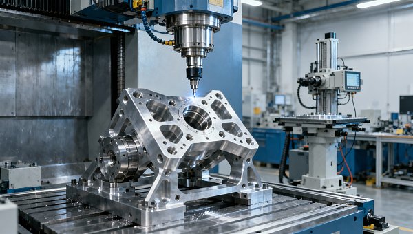
How Should You Compare TechStat Vanguard 5-Axis CNC Tolerances?
Publication Date
author
How Should You Compare TechStat Vanguard 5-Axis CNC Tolerances?
A quoted tolerance means little without the conditions behind it. For engineering and procurement teams, a TechStat Vanguard 5-axis CNC tolerance comparison should distinguish machine positioning accuracy from verified part tolerances—and account for material, geometry, thermal stability, fixturing, and inspection methods. Neither AS9100 nor ISO 13485 certification alone proves a supplier can hold your drawing requirements. The useful comparison is not which supplier advertises the smallest number, but which can demonstrate repeatable compliance with your application’s acceptance criteria.
TechStat Vanguard’s stated approach, “Engineering Truth Through Data,” provides a practical starting point: strip away unsupported claims and examine the evidence. TSV is positioned as an engineering benchmarking platform, not a machine manufacturer. Its name should therefore frame how capabilities are evaluated, rather than imply a proprietary CNC tolerance specification.
Start by asking what the tolerance actually describes
“Accuracy,” “repeatability,” and “tolerance” are often used interchangeably in quotations. They describe different things. A machine can return consistently to a commanded position while remaining offset from the intended position. It can also perform well during an unloaded positioning test yet produce unacceptable parts under cutting forces.
The drawing defines permitted variation in the finished component. Machine specifications describe equipment performance under stated test conditions. Process capability concerns the distribution of results produced by a particular manufacturing process. None of these is a substitute for the others.
Be particularly careful with a blanket statement such as “micron-level machining.” Without identifying the feature, material, component size, and inspection method, it is not a meaningful acceptance commitment. A supplier should be able to connect its claim to specific drawing characteristics.
Compare the same features under the same drawing rules
A close-tolerance bore is not equivalent to a tightly controlled freeform surface. Bore size, cylindricity, surface profile, and true position describe different requirements. Even when their numerical limits look similar, their manufacturing and inspection demands can differ substantially.
Before comparing suppliers, identify the characteristics that control function. On a robotic assembly, these might be bearing-seat geometry and the relationship between mounting faces. On an aerospace bracket, hole position relative to the datum structure may matter more than a nonfunctional outside dimension. A sensor housing may depend on alignment between an optical mounting surface and a locating feature.
The applicable drawing convention also matters. ASME Y14.5 and ISO geometrical product specification standards should not be treated as interchangeable shorthand. Confirm the specified standard and edition, datum definitions, material-condition modifiers, and any drawing-specific exceptions. Suppliers must price and inspect against the same interpretation.
Separate tolerance from surface texture as well. A smooth surface can be dimensionally incorrect; a conforming dimension can still fail a roughness requirement. Where both affect function, request distinct evidence rather than allowing a surface-finish claim to stand in for geometric conformity.
Five-axis motion changes the error picture
Five-axis machining can reduce setups and improve access to complex features. That can help preserve relationships between surfaces that would otherwise require reclamping. It does not automatically make every feature more accurate.
Rotary-axis errors, pivot-location errors, tool-length uncertainty, and machine kinematic calibration all affect tool-tip position. An angular error creates a larger positional effect as distance from the relevant rotation center increases. Consequently, a result achieved on a compact test piece may not transfer directly to a larger component with long tool reach.
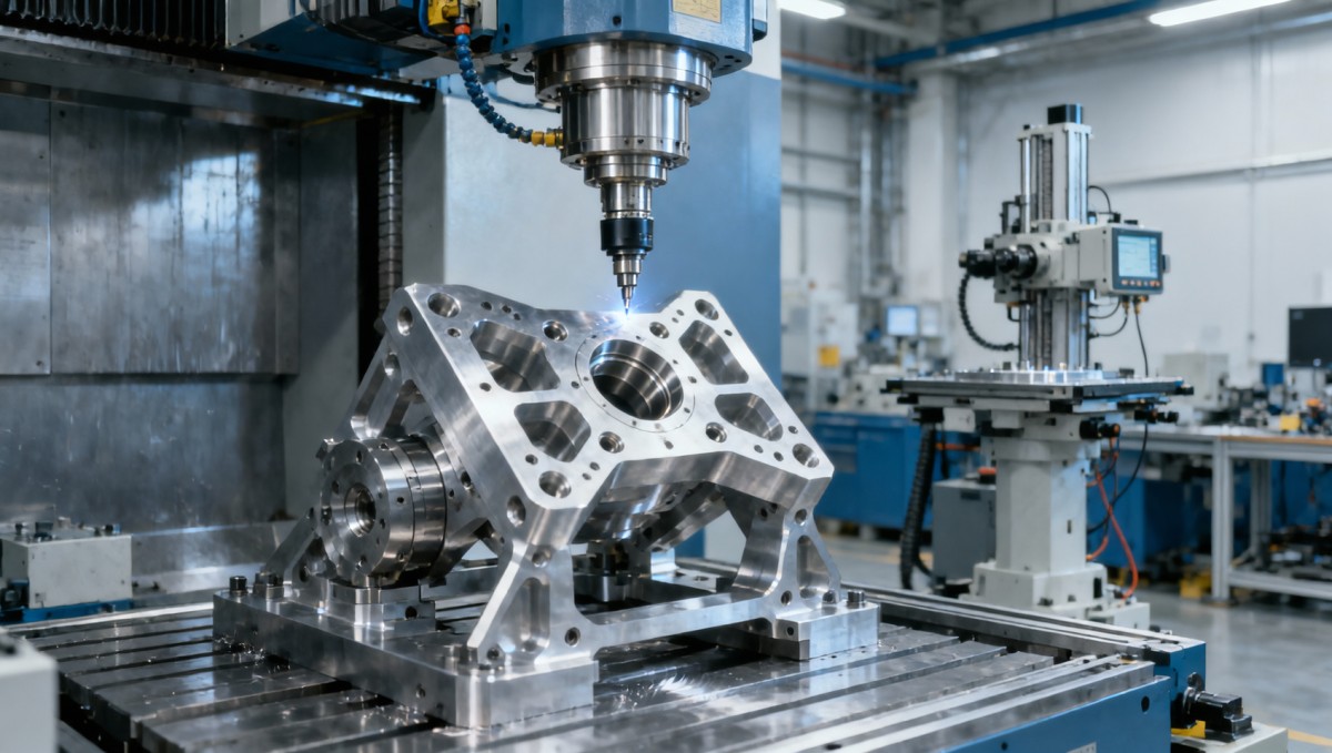
Ask whether the quoted process uses indexed 3+2 machining, simultaneous five-axis motion, or a combination. Indexed machining holds the rotary axes in position during a cutting operation. Simultaneous machining coordinates movement across multiple axes, making performance during coordinated motion more relevant. Neither approach is universally superior; the right choice depends on access, geometry, tool engagement, and required feature relationships.
Machine acceptance evidence can support the assessment. Relevant parts of ISO 230 address machine-tool testing, while ISO 10791 covers machining-center test conditions. Request the specific part and test used, not merely a claim that testing followed “ISO standards.” These results help characterize equipment but do not replace inspection of representative parts.
Material, temperature, and workholding belong in the comparison
A supplier’s demonstrated performance on a rigid aluminum block says little about a thin-walled titanium component or a distortion-prone stainless-steel housing. Cutting forces, heat generation, residual stress, tool wear, and stiffness change with material and geometry. Capability evidence should resemble the proposed work closely enough to support a decision.
Thermal conditions deserve particular attention when tolerances are tight. ISO 1 establishes 20°C as the standard reference temperature for geometrical and dimensional properties. That does not mean every inspection must physically occur at exactly that temperature, but deviations require appropriate treatment. Ask how part temperature, stabilization time, and thermal compensation are handled.
A part can also pass inspection while clamped and move outside tolerance after release. Thin walls, slender ribs, and large pockets are especially worth reviewing. Clarify whether acceptance measurements represent the free-state component or a specified restrained condition. Fixture design, clamping force, and the order of roughing and finishing should support that requirement.
Finally, establish when compliance is required. Heat treatment, anodizing, plating, polishing, and other downstream operations can alter dimensions or geometry. A report for the as-machined condition is insufficient if the drawing applies to the finished, treated part. The quotation should identify who owns post-processing verification and corrective action.
Inspection evidence must be strong enough to resolve the tolerance
A coordinate measuring machine report is useful, but the instrument’s name alone proves little. Probe configuration, access, point distribution, alignment strategy, software evaluation, and temperature can influence the result. Sparse sampling may miss local surface deviations, particularly on complex profiles.
For each critical characteristic, agree on the measurement method before production. The inspection plan should explain how datums are established, which surfaces are sampled, and how results are evaluated. Where measurement uncertainty is significant relative to the allowed variation, agree on the conformity decision rule, including any guard band. Borderline measurements should not become a dispute after shipment.
On-machine probing is valuable for setup, offset adjustment, and process monitoring. However, it can share error sources with the machine that produced the part. Independent verification is especially important when the risk involves machine geometry or calibration. Use probing as part of the control strategy, not automatic proof of final conformity.
Request traceable measurement records rather than a screenshot showing “pass.” A usable report links the drawing revision, part identity, characteristic, measured value, acceptance limit, inspection method, and disposition. Calibration status and relevant uncertainty information should be available for review.
One good part is not a production capability study
A first article demonstrates what was achieved on the inspected article. It does not, by itself, establish consistency across tool changes, shifts, material lots, or production runs. This distinction matters when a supplier uses extensive manual adjustment to achieve a successful sample.
Capability indices such as Cp and Cpk can help evaluate production variation, but only when their assumptions and data are appropriate. Ask for the sample size, collection period, subgrouping, process conditions, and evidence of stability. Non-normal data and one-sided specifications need suitable treatment. An index without its underlying context is another unsupported headline number.
For low-volume aerospace or medical work, there may not be enough comparable observations for a credible capability estimate. Do not force a statistical claim from insufficient data. A stronger approach may combine representative trials, feature-level inspection, documented process controls, and a risk-based sampling plan agreed with the customer.
AS9100 and ISO 13485 certification can support confidence in the relevant quality-management system. They do not prescribe universal five-axis machining tolerances or certify that every feature is achievable. Check the certificate’s scope, covered site, and validity, then assess machining and inspection capability separately.
Turn the comparison into a qualification decision
A useful TechStat Vanguard 5-axis CNC tolerance comparison begins with a common evidence package: the controlled drawing, material and treatment requirements, critical characteristics, inspection expectations, and expected production volume. Give each supplier the same information and ask it to identify exceptions explicitly.
Then compare demonstrated capability, not just promised limits. Prefer evidence from comparable features and materials. Review the proposed setup sequence, downstream processing, inspection resources, and response to drift or nonconformance. A supplier that explains its constraints clearly may be easier to qualify than one that accepts every requirement without technical review.
This is where TSV’s data-driven benchmarking position is most useful: connecting a claimed parameter to its test conditions, traceability, and relevance to the application. The objective is not to select the smallest advertised tolerance. It is to establish which process can meet the drawing reliably, at the required delivery rate, with evidence sufficient for acceptance.
Before approving production, resolve any disagreement over datum interpretation, finished-part condition, measurement uncertainty, and sampling. Put those decisions into the inspection and acceptance plan. A tolerance comparison becomes actionable when both parties know exactly what will be measured—and what happens if the result falls outside the agreed limits.
Search News
Hot Articles
- Carbon Fiber StructuresHow to Specify Aerospace Carbon Fiber Assemblies for Lightweight, Load-Bearing PartsJul 11, 2026
- Machine VisionXiaomi, Alibaba DAMO Academy Drive Open-Source Robotics Model Ecosystem, Lowering Algorithm Development Barriers for Overseas SMEs Adopting Chinese Robotics SolutionsMar 30, 2026
- Cobots & ArmsShanxi 'AI+' Conference Showcases Embodied Intelligence with Multinational Buyer Engagement: Key Industry ImplicationsMar 30, 2026
Popular Tags
Recommended News
 Jul 11, 2026How to Specify Aerospace Carbon Fiber Assemblies for Lightweight, Load-Bearing PartsAerospace carbon fiber assemblies: learn how to specify laminate design, load data, joining methods, and inspection controls for lighter, reliable load-bearing aerospace parts.Elena Rostova (UAV Systems Researcher)
 Mar 30, 2026Xiaomi, Alibaba DAMO Academy Drive Open-Source Robotics Model Ecosystem, Lowering Algorithm Development Barriers for Overseas SMEs Adopting Chinese Robotics SolutionsXiaomi & Alibaba DAMO Academy's open-source robotics models lower algorithm barriers for global SMEs. Boost efficiency in manufacturing, logistics & smart retail with ROS 2 compatible solutions.TSV Data Lab
 Mar 30, 2026Shanxi 'AI+' Conference Showcases Embodied Intelligence with Multinational Buyer Engagement: Key Industry ImplicationsShanxi 'AI+' Conference highlights embodied intelligence with Tesla, Ubtech & Jiantao showcasing multimodal robotics. 40+ global buyers validated tech on-site, creating new B2B channels for industrial automation & AI solutions.Chen Wei (Automation Lead Engineer)
 Mar 30, 2026Zhongguancun Unveils 6G Integrated Sensing-Computing-Intelligence Platform to Empower Embodied Robots for Global Industrial ApplicationsZhongguancun's new 6G platform revolutionizes industrial robotics with <10ms latency, empowering global automotive, logistics & port automation. Discover how this tech boosts China's smart manufacturing exports.TSV Data Lab
 Mar 30, 2026Mech-Mind Tianjin Embodied Intelligence R&D and Production Base Goes Live, Cutting Delivery Time by 20%–30% for Global Customized AMR+Vision SolutionsMech-Mind's Tianjin AMR+Vision production base cuts delivery time by 20%-30% for欧美 & Latin American markets. Discover how this PLd-certified facility accelerates customized robotics solutions for smart manufacturing and logistics.Chen Wei (Automation Lead Engineer)
 Mar 30, 2026Boao Forum Reveals 'Co-evolution of Big and Small Brains' Trend in Humanoid Robots, China's Embodied Intelligence Accelerates Adaptation to Overseas Manufacturing Service ScenariosDiscover how China's humanoid robots, featuring 'Co-evolution of Big and Small Brains,' are revolutionizing global manufacturing. Learn about Embodied Tian Gong 3.0's ISO compliance and overseas deployment at Boao Forum 2026.Chen Wei (Automation Lead Engineer)
 Mar 30, 2026China Railway Industrial Secures Patent for Embodied Robotics in Material Handling, Boosting High-Precision Delivery Capabilities for Overseas Infrastructure and Manufacturing ProjectsChina Railway Industrial's new patent for embodied robotics in material handling boosts high-precision delivery for global infrastructure & manufacturing. Discover how this innovation enhances logistics accuracy in automotive, rail transit & EPC projects.Chen Wei (Automation Lead Engineer)
 Oct 15, 2026R&D Cost Reduction Services: How to Evaluate Fees, Savings, and ROIEvaluate R&D cost reduction services with confidence. Compare fees, verify savings, and calculate ROI without compromising performance. Discover how to choose a provider that delivers real value.Chen Wei (Automation Lead Engineer)
 Oct 15, 2026How Should You Compare TechStat Vanguard 5-Axis CNC Tolerances?TechStat Vanguard 5-axis CNC tolerance comparison: learn how to verify part accuracy, assess inspection evidence, and choose suppliers that reliably meet your drawing requirements.Dr. Marcus Vance
 Oct 14, 2026Drone Frame Composites: Carbon Fiber vs. Fiberglass for Weight and StiffnessExplore drone structural materials composites: compare carbon fiber and fiberglass for weight, stiffness, cost, and antenna compatibility. Find the right material for your drone frame.Elena Rostova (UAV Systems Researcher)
 Oct 13, 2026Smart Cameras vs. PC-Based Machine Vision: Which Fits High-Speed Inspection?This industrial product comparison for machine vision weighs smart cameras vs. PC-based systems on latency, throughput, and cost. Discover your best fit for high-speed inspection.TSV Data Lab
 Oct 12, 2026How to Verify RoHS Compliance in Industrial Sensing Systems Before DeploymentRoHS compliant sensing systems: learn how to verify materials, supplier declarations, testing, and configuration controls before industrial deployment.TSV Data Lab
 Oct 11, 2026How Procurement-Oriented Content Taxonomy Improves B2B Buying JourneysProcurement-oriented content taxonomy streamlines B2B buying journeys with clearer evidence, supplier comparisons, risk visibility, and faster approvals.TSV Data Lab
 Oct 10, 2026How to Select a Machine Performance Monitoring Platform for OEE and Downtime ReductionMachine performance monitoring platform selection guide: validate machine states, OEE data, downtime reasons, integrations, and scalability to reduce losses with confidence.TSV Data Lab
 Oct 08, 2026How to Machine Inconel 625 Blades Without Heat Cracks or Edge ChippingInconel 625 blade machining guide: prevent heat cracks, edge chipping, chatter, and work hardening with proven tooling, cooling, fixturing, and inspection strategies.Dr. Marcus Vance
 Oct 07, 2026How to Evaluate an HMI Panel Distributor for Industrial Automation ProjectsHMI panel distributor evaluation guide: verify technical compatibility, traceability, supply reliability, lifecycle support, and total cost for automation projects.Victor Lin (Chief Software Architect)
 Oct 06, 2026Navigation Fault Tolerance Standards for AMRs: What Safety Teams Must VerifyNavigation fault tolerance standards: learn what AMR safety teams must verify, from localization loss and sensor faults to stopping distance, safe restart, and site-specific validation.Chen Wei (Automation Lead Engineer)
 Oct 05, 2026Calculating Edge Computing Total Cost of Ownership Across Distributed SitesEdge computing ownership cost explained: calculate deployment, energy, connectivity, security, remote support, and refresh costs across distributed sites.TSV Data Lab
 Oct 04, 2026CAD/CAM Benchmarking in the GCC: What Manufacturers Should Ask a ConsultantCAD CAM benchmark consultant GCC guide: learn the key questions manufacturers should ask to validate post-processors, workflows, machine performance, and production risk.Victor Lin (Chief Software Architect)
 Oct 03, 2026Selecting Automotive Radar Sensor Modules for ADAS Range, Resolution, and IntegrationAutomotive radar sensor module selection guide for ADAS: compare range, resolution, field of view, latency, and integration to build safer, reliable vehicle systems.TSV Data Lab
 Oct 02, 2026How to Qualify Machined Parts Suppliers for Hard Tech ProgramsHard tech supply chain machined parts demand rigorous supplier qualification. Learn how to assess capability, traceability, quality controls, and delivery resilience.Dr. Marcus Vance
 Oct 01, 2026How to Select an Outdoor Security Radar Sensor for Perimeter Detection?Outdoor security radar sensor selection guide: compare range, accuracy, false-alarm control, integration, and field testing for reliable perimeter detection.TSV Data Lab
 Sep 30, 2026How to Evaluate Solid-State LiDAR Hardware for Outdoor Autonomous VehiclesSolid state LiDAR hardware evaluation guide for outdoor autonomous vehicles—compare range, point-cloud quality, environmental resilience, integration, and safety.TSV Data Lab
 Sep 29, 2026ISO 9283 Repeatability: How to Evaluate Cobot Positioning PerformanceISO 9283 cobot repeatability explained: learn how payload, reach, approach direction, and test conditions affect positioning performance and cell capability.Chen Wei (Automation Lead Engineer)