How Should You Balance Cobot Payload Against Reach?
Publication Date
author
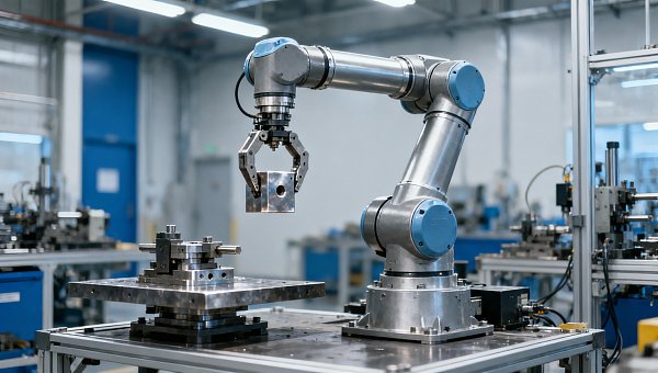
A cobot that reaches every station can still fail the application if its tooling and workpiece exceed the allowable load for the required motion. The right balance is not the highest payload combined with the longest reach. It is sufficient usable reach with a verified load configuration, acceptable cycle time, and safe operation throughout the task.
Balancing cobot payload versus reach therefore requires more than comparing two headline specifications. End-effector mass, center-of-gravity offsets, load inertia, robot posture, and acceleration determine whether a candidate can perform the job. A shorter arm with a well-positioned base may outperform a longer arm operating near its workspace boundary; a higher-payload model may be necessary even when the workpiece itself is light.
Payload and reach are linked, but not by a universal trade-off
Rated payload describes the load a robot can carry under the manufacturer’s specified conditions. Published reach describes a geometric extent, generally referenced to the robot’s mounting frame and a defined point on the arm. Neither number alone establishes whether the robot can handle a particular workpiece at a particular station.
Longer links increase the lever arm through which gravity and acceleration load the joints. However, robot designs differ in joint torque capability, link mass, geometry, transmission design, and controller limits. There is no reliable rule that doubling reach halves payload, nor should a payload rating automatically be assumed to decrease in direct proportion to extension.
Some robots support their rated payload across a broad workspace when the load meets specified center-of-gravity and inertia conditions. Others have operating restrictions tied to configuration or motion. The relevant evidence is the manufacturer’s load documentation and application-validation tools—not an inferred relationship between kilograms and millimeters.
Count everything the robot carries
The workpiece is only part of the payload. The load calculation should include the gripper or process tool, adapter plates, tool changers, sensors, brackets, and other flange-mounted equipment. Account for cables and hoses according to their mounting and the manufacturer’s guidance; externally routed services can also apply forces that a simple mass total misses.
Consider an illustrative handling task with a 5 kg workpiece, a 2.5 kg gripper, a 0.8 kg adapter, and 0.7 kg of carried accessories. The combined load is 9 kg. A 10 kg-rated cobot passes an initial mass check, but that does not yet establish suitability. The load’s position and rotational inertia may be more restrictive than its total mass.
Use the heaviest credible production configuration rather than an average. A dual gripper may temporarily hold two parts. A dispensing tool may change mass as material is consumed. Different product variants can move the combined center of gravity even when their masses are similar. The controlling condition may occur during transfer rather than at pickup.
A blanket payload reserve percentage is not a substitute for this calculation. Additional capacity can accommodate uncertainty or planned tooling changes, but it cannot make an out-of-limit center of gravity acceptable. Specify the reserve against an identified need, such as a heavier product variant, rather than treating it as proof of dynamic capability.
A light load can still be difficult to move
The distance between the flange and the combined load’s center of gravity affects the moment applied to the wrist. For a simple static illustration, the gravitational moment is M = m × g × d, where d is the perpendicular distance from the relevant axis to the weight’s line of action.
A 9 kg load with a 0.15 m perpendicular offset produces approximately 13.2 N·m of gravitational moment. At 0.30 m, that moment becomes approximately 26.5 N·m. These figures illustrate the effect of offset; they are not allowable wrist limits, and they do not include acceleration, process forces, or the robot’s own link loads.
This explains why a compact gripper holding a part close to the flange can be easier to accommodate than a lighter tool with a long extension. Reducing tool offset may resolve a load-limit problem without changing the robot. Increasing reach by fitting a long tool, however, can simply move the constraint from arm geometry to wrist loading.
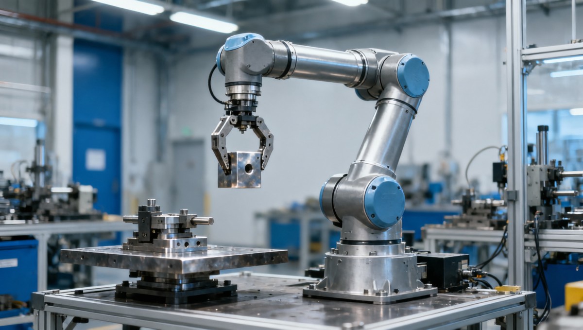
Rotational inertia adds another distinction. Two loads with identical mass and center of gravity can resist angular acceleration differently if their mass is distributed differently. A broad panel or long shaft can demand more wrist torque during rotation than a compact block. In a simplified point-mass model, inertia increases with the square of the distance from the rotation axis.
Check the combined tool-and-part center of gravity and inertia against the manufacturer’s permitted values, using the required coordinate system. Enter the correct load data into the controller and update it when the carried configuration changes. Controller compensation does not authorize operation outside mechanical limits.
Usable reach is smaller than a simple radius suggests
A station located inside the published reach envelope is not necessarily accessible. The robot must reach the tool center point with the correct orientation, avoid obstacles, and retain a valid joint configuration. A machine-tending gripper may need to enter a door opening, align with a chuck, and withdraw along a constrained path. Touching the target position is only one requirement.
Evaluate the full path: approach, engagement, process motion, withdrawal, and transfer. Include part dimensions, gripper opening, fixtures, machine doors, and service routing. A pickup point may be reachable while the clearance position above it is not. Similarly, a palletizing arm may reach a pallet corner at one height but lack a suitable configuration for another layer.
Operation near a workspace boundary can leave little flexibility for orientation changes or obstacle avoidance. Near a kinematic singularity, certain tool motions can require high joint speeds, leading to controller slowdown or an alternative path. Longer reach does not inherently eliminate this problem; robot geometry and the mounting location determine where it occurs.
Base placement is therefore part of robot selection. Moving the pedestal closer to the demanding station, adjusting its height, or changing fixture orientation can reduce both reach requirements and unfavorable posture. Compare these layout changes before committing to a larger arm. Verify the proposed mounting orientation and supporting structure against the robot’s installation requirements.
Compare candidates at the required cycle time
A robot may carry a load and reach every station yet still miss the production target. Acceleration and deceleration generate additional joint demands. Long offsets and high inertia can restrict motion performance, while precision placement may require settling time before release or process engagement.
Headline maximum speed is particularly weak evidence for short handling cycles. The arm may spend much of each movement accelerating and decelerating without reaching that speed. Gripper actuation, sensing, machine handshakes, and dwell time also contribute to the complete cycle.
For the illustrative 9 kg application, three configurations deserve different judgments:
- A longer-reach, 10 kg-rated arm: It may satisfy geometry and mass, but needs close verification of load offset, inertia, and loaded trajectory performance.
- A shorter-reach, higher-payload arm: It may offer suitable load capability, provided a revised base position gives access to all required poses.
- A longer-reach, higher-payload arm: It may satisfy both constraints, but its larger physical envelope and mounting demands must also fit the cell.
These are alternatives to validate, not a ranking. A higher payload rating does not automatically mean better cycle time, and a longer arm does not automatically mean poor precision. Compare the candidates using the same tooling model, workpiece configurations, trajectory, process requirements, and safety assumptions.
Simulation is useful for rejecting infeasible layouts and estimating motion performance. A representative application trial provides stronger evidence for loaded cycle time, settling, cable behavior, and process quality. Where a purchase depends on a tight performance target, define acceptance conditions before ordering.
Mechanical capacity and collaborative safety are separate limits
A robot’s ability to carry a payload does not establish that it can move that payload safely beside people. The application requires a risk assessment that includes the tool, workpiece, motion, surrounding structures, and foreseeable access. Relevant robot-system safety requirements include the ISO 10218 series; ISO/TS 15066 provides guidance for collaborative applications where applicable.
A heavier carried load can affect stopping behavior and potential contact consequences. Sharp workpieces, rigid tooling, and trapping points may be decisive hazards even at low mass. Power-and-force-limited operation may require speeds below those needed for production, or the application may need separation monitoring or guarding instead.
Reach also changes the safety problem. A longer arm can access more stations, but it can sweep through more space and create additional trapping locations against fixed equipment. Compare achievable cycle time under the intended protective measures—not under unrestricted motion settings that the installed cell cannot use.
Turn the comparison into an acceptance decision
A useful selection specification describes the application rather than requesting only a minimum payload and reach. It records the combined load configurations, center-of-gravity coordinates, inertia data, target poses and orientations, mounting arrangement, clearance constraints, process forces, and required complete cycle time.
Ask for evidence that addresses those conditions directly. Manufacturer load charts establish whether the load is permitted; reach studies establish whether the poses and paths are feasible; motion evaluation establishes whether throughput is achievable. Precision processes also need confirmation of tool-tip performance under the actual load and posture. Published repeatability alone does not establish absolute positioning accuracy or loaded stiffness.
If no candidate comfortably meets both payload and reach requirements, reconsider the application geometry before increasing robot size. A lighter tool, shorter adapter, relocated fixture, or better base position may remove the limiting condition. A linear axis can extend coverage, but adds coordinated motion, installation, and safety requirements that must be evaluated as part of the system.
The selection is defensible when every required pose is accessible, every carried configuration remains within documented load limits, and the complete task meets its timing and process requirements under the intended safety conditions. That is the practical balance: not trading kilograms against millimeters on a specification sheet, but matching load capability and usable workspace to the same validated job.
Search News
Hot Articles
- Carbon Fiber StructuresHow to Specify Aerospace Carbon Fiber Assemblies for Lightweight, Load-Bearing PartsJul 11, 2026
- Machine VisionXiaomi, Alibaba DAMO Academy Drive Open-Source Robotics Model Ecosystem, Lowering Algorithm Development Barriers for Overseas SMEs Adopting Chinese Robotics SolutionsMar 30, 2026
- Cobots & ArmsShanxi 'AI+' Conference Showcases Embodied Intelligence with Multinational Buyer Engagement: Key Industry ImplicationsMar 30, 2026
Popular Tags
Recommended News
 Jul 11, 2026How to Specify Aerospace Carbon Fiber Assemblies for Lightweight, Load-Bearing PartsAerospace carbon fiber assemblies: learn how to specify laminate design, load data, joining methods, and inspection controls for lighter, reliable load-bearing aerospace parts.Elena Rostova (UAV Systems Researcher)
 Mar 30, 2026Xiaomi, Alibaba DAMO Academy Drive Open-Source Robotics Model Ecosystem, Lowering Algorithm Development Barriers for Overseas SMEs Adopting Chinese Robotics SolutionsXiaomi & Alibaba DAMO Academy's open-source robotics models lower algorithm barriers for global SMEs. Boost efficiency in manufacturing, logistics & smart retail with ROS 2 compatible solutions.TSV Data Lab
 Mar 30, 2026Shanxi 'AI+' Conference Showcases Embodied Intelligence with Multinational Buyer Engagement: Key Industry ImplicationsShanxi 'AI+' Conference highlights embodied intelligence with Tesla, Ubtech & Jiantao showcasing multimodal robotics. 40+ global buyers validated tech on-site, creating new B2B channels for industrial automation & AI solutions.Chen Wei (Automation Lead Engineer)
 Mar 30, 2026Zhongguancun Unveils 6G Integrated Sensing-Computing-Intelligence Platform to Empower Embodied Robots for Global Industrial ApplicationsZhongguancun's new 6G platform revolutionizes industrial robotics with <10ms latency, empowering global automotive, logistics & port automation. Discover how this tech boosts China's smart manufacturing exports.TSV Data Lab
 Mar 30, 2026Mech-Mind Tianjin Embodied Intelligence R&D and Production Base Goes Live, Cutting Delivery Time by 20%–30% for Global Customized AMR+Vision SolutionsMech-Mind's Tianjin AMR+Vision production base cuts delivery time by 20%-30% for欧美 & Latin American markets. Discover how this PLd-certified facility accelerates customized robotics solutions for smart manufacturing and logistics.Chen Wei (Automation Lead Engineer)
 Mar 30, 2026Boao Forum Reveals 'Co-evolution of Big and Small Brains' Trend in Humanoid Robots, China's Embodied Intelligence Accelerates Adaptation to Overseas Manufacturing Service ScenariosDiscover how China's humanoid robots, featuring 'Co-evolution of Big and Small Brains,' are revolutionizing global manufacturing. Learn about Embodied Tian Gong 3.0's ISO compliance and overseas deployment at Boao Forum 2026.Chen Wei (Automation Lead Engineer)
 Mar 30, 2026China Railway Industrial Secures Patent for Embodied Robotics in Material Handling, Boosting High-Precision Delivery Capabilities for Overseas Infrastructure and Manufacturing ProjectsChina Railway Industrial's new patent for embodied robotics in material handling boosts high-precision delivery for global infrastructure & manufacturing. Discover how this innovation enhances logistics accuracy in automotive, rail transit & EPC projects.Chen Wei (Automation Lead Engineer)
 Oct 21, 2026China’s Industrial Robot Exports Near RMB 10 Billion in First Nine Months of 2026China’s industrial robot exports neared RMB 10 billion in January–September 2026, with value rising faster than volume. Explore the data and what it could mean for suppliers.Chen Wei (Automation Lead Engineer)
 Oct 21, 2026Low-Latency Industrial Data Processing: Pricing and Key Cost DriversExplore industrial data latency price drivers, from edge hardware to integration and support. Learn how to compare quotes, verify performance, and avoid unnecessary costs.TSV Data Lab
 Oct 20, 2026KUKA Launches iiQKA.AI Vision to Simplify Industrial Image ProcessingKUKA iiQKA.AI Vision simplifies industrial image processing with controller-based 2D and 3D vision. Explore drag-and-drop setup for vision-guided automation.TSV Data Lab
 Oct 20, 2026Smart Industrial Edge Devices: Key Criteria for Legacy PLC IntegrationChoose smart industrial edge devices for legacy PLC integration. Discover key criteria for compatibility, data quality, security, and reliable collection without disrupting control.TSV Data Lab
 Oct 19, 2026Choosing a Radar Sensor by Application: Range, Resolution, and Field of ViewSimplify radar sensor application based product selection. Compare range, resolution, and field of view to avoid blind spots and choose with confidence. Explore the guide.TSV Data Lab
 Oct 18, 2026Comparing Material Options for Procurement: Specs, Costs, and Supply RisksExplore procurement oriented technical content on material options, specs, costs, and supply risks. Compare alternatives to cut hidden expenses and make confident sourcing decisions.Dr. Marcus Vance
 Oct 17, 20265-Axis CNC Positioning Accuracy: How to Interpret ISO 230-2 Test ResultsAssess 5 axis CNC machining positioning accuracy with ISO 230-2. Learn to interpret repeatability, reversal error, and test conditions to compare suppliers and make confident acceptance decisions.Dr. Marcus Vance
 Oct 16, 2026Choosing a Rugged Edge AI Box Supplier: Thermal Tests and Lifecycle SupportChoose a rugged edge AI box supplier with proven thermal performance and reliable lifecycle support. Discover the tests and commitments to verify before you buy.TSV Data Lab
 Oct 15, 2026R&D Cost Reduction Services: How to Evaluate Fees, Savings, and ROIEvaluate R&D cost reduction services with confidence. Compare fees, verify savings, and calculate ROI without compromising performance. Discover how to choose a provider that delivers real value.Chen Wei (Automation Lead Engineer)
 Oct 21, 2026How Should You Balance Cobot Payload Against Reach?Explore cobot payload versus reach to choose the right robot. Learn how tooling, load limits, workspace, and cycle time affect performance—and avoid costly selection mistakes.Chen Wei (Automation Lead Engineer)
 Oct 20, 2026How Do You Measure Industrial IoT Gateway Latency Under Load?Measure industrial IoT gateway latency under load with reliable timestamps, realistic traffic, and tail-latency analysis. Discover how to expose bottlenecks and choose the right gateway.TSV Data Lab
 Oct 19, 2026How Do You Verify That Precision Machined Parts Meet Tolerances?Master precision machining tolerance verification with the right tools, datum setups, and acceptance rules. Learn how to validate parts confidently and reduce costly inspection errors.Dr. Marcus Vance
 Oct 18, 2026What Should an AS9100 Machining Supplier Checklist Include?Build an AS9100 machining supplier checklist that verifies capability, traceability, inspection, and outsourced processes. Discover what to check before approving your next aerospace supplier.Dr. Marcus Vance
 Oct 17, 2026How Should You Interpret Industrial Robot Repeatability Specs?Decode industrial robot repeatability specifications, understand ISO 9283 test conditions, and avoid costly selection mistakes. Learn how to verify performance for your process.Chen Wei (Automation Lead Engineer)
 Oct 16, 2026How Can You Fairly Compare MTBF Across Industrial Servo Motors?Make a fair industrial servo motor MTBF comparison with matched operating profiles, failure criteria, and confidence bounds. Discover how to assess reliability beyond advertised numbers.Chen Wei (Automation Lead Engineer)
 Oct 15, 2026How Should You Compare TechStat Vanguard 5-Axis CNC Tolerances?TechStat Vanguard 5-axis CNC tolerance comparison: learn how to verify part accuracy, assess inspection evidence, and choose suppliers that reliably meet your drawing requirements.Dr. Marcus Vance
 Oct 14, 2026Drone Frame Composites: Carbon Fiber vs. Fiberglass for Weight and StiffnessExplore drone structural materials composites: compare carbon fiber and fiberglass for weight, stiffness, cost, and antenna compatibility. Find the right material for your drone frame.Elena Rostova (UAV Systems Researcher)