Can a ToF camera really hold millimeter depth accuracy?
Publication Date
author
Can a ToF camera truly deliver millimeter-grade depth in real industrial conditions? For engineers, buyers, and decision-makers, the answer depends on more than marketing claims. This article examines tof camera depth accuracy millimeter alongside machine vision sub-pixel accuracy, lidar sunlight interference resistance, and solid state lidar point cloud density to reveal what real measurement performance looks like.
What does millimeter depth accuracy really mean for a ToF camera?
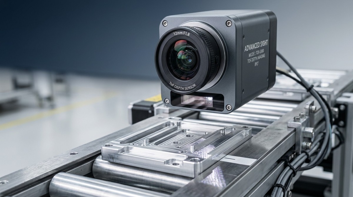
In procurement discussions, “millimeter accuracy” is often treated as a single number, but in practice it is a layered specification. A ToF camera may show depth repeatability within a narrow range under controlled lab conditions, yet that does not automatically translate into absolute depth accuracy across a full working distance of 0.3 m to 5 m. For industrial users, the key issue is whether the system can maintain stable error bounds at the distance, angle, reflectivity, and ambient light level that the application actually demands.
A more useful way to interpret tof camera depth accuracy millimeter is to separate three questions. First, what is the minimum depth step the sensor can resolve? Second, what is the repeatability over repeated captures at the same position? Third, what is the absolute error after calibration when the target moves across the field of view? A vendor may promote a small resolution figure, while the usable system error in production remains several millimeters larger due to optics, thermal drift, and signal processing limits.
This is why engineering teams should ask for test conditions before trusting any headline claim. Was the result measured on a matte target or a reflective metal surface? Was the camera operating indoors at 20°C to 25°C, or near a machine cell where temperature changes by 10°C or more during a shift? Was the object stationary, or moving on a conveyor at 0.5 m/s to 1.5 m/s? These factors decide whether “millimeter-grade” means a usable production metric or only a controlled demonstration value.
At TechStat Vanguard, the engineering view is simple: parameters do not lie, but incomplete parameters mislead. For B2B buyers, the correct question is not whether a ToF camera can ever reach millimeter-level depth. It is whether the entire sensing chain can hold that performance in your defined tolerance window, across a realistic duty cycle, with acceptable calibration effort and total integration risk.
Three definitions procurement teams should separate
Before comparing sensor options, it helps to distinguish between measurement terms that are frequently mixed together in vendor sheets and distributor summaries.
- Depth resolution: the smallest measurable change in distance under signal-rich conditions. This is not the same as field accuracy.
- Repeatability: the spread of repeated readings at a fixed position, often important for process stability over 100 to 1,000 frames.
- Absolute accuracy: the gap between measured and true distance after calibration, usually the most relevant metric for metrology-like tasks.
- System accuracy: the final result after lens distortion, mounting tolerance, vibration, thermal change, and software filtering are included.
When these four terms are separated, many optimistic claims become easier to audit. A ToF camera can be excellent for volume detection, bin fill estimation, or robot approach guidance, while still being unsuitable for tight gauging tasks that expect consistent ±1 mm performance across the full scene.
Which factors most strongly affect real-world ToF camera depth accuracy?
The first major factor is target surface behavior. Dark, glossy, translucent, and highly reflective materials all change the returned light signal. In packaging, electronics, and precision machining environments, a camera may need to view black rubber, brushed aluminum, coated glass, or composite materials in the same cell. Each material can alter signal amplitude, introduce multipath effects, or reduce confidence in depth points. That means the same ToF camera can behave very differently between one SKU and the next.
The second factor is operating distance and field geometry. Many systems perform best in a central zone, then lose precision toward the edge of the field. If a supplier quotes strong tof camera depth accuracy millimeter performance at 0.5 m, buyers should verify whether the same camera still holds acceptable error at 1.5 m, 2 m, or 3 m. In robotics and material handling, a wider field of view often trades away local point precision, so the optical setup matters as much as the sensor principle.
The third factor is ambient light and interference. Outdoor, near-window, or high-bay industrial installations can expose the sensor to strong sunlight or variable infrared noise. This is where lidar sunlight interference resistance becomes a useful comparison point. Solid-state LiDAR and ToF systems both depend on active light, but their anti-interference behavior is not identical. Applications in agriculture, UAV payload sensing, and yard logistics should test under actual daytime conditions instead of relying on indoor benchmarks.
The fourth factor is calibration stability over time. A system may pass acceptance testing on day one, then drift after 2 to 4 weeks of thermal cycling, mechanical vibration, or enclosure contamination. Operators often underestimate the impact of lens contamination, mounting relaxation, and software updates on depth consistency. For a production line running 16 to 24 hours per day, maintainability can matter more than laboratory precision.
A practical parameter view for engineering review
The table below is not a brand ranking. It is a screening framework that helps information researchers, operators, procurement teams, and executives ask more precise technical questions during sourcing.
For decision-makers, this table turns vague sensor marketing into an audit path. If a vendor cannot explain how performance changes across these four factors, the procurement risk remains high, even if the brochure highlights millimeter-class depth performance.
ToF vs machine vision vs solid-state LiDAR: which technology fits which job?
A ToF camera is not automatically better or worse than machine vision or LiDAR. It depends on the measurement target. For many industrial tasks, machine vision sub-pixel accuracy can outperform ToF in 2D edge location, diameter inspection, or alignment of high-contrast features. If the requirement is to detect a boundary on a stable plane with good optics and lighting, sub-pixel methods may provide finer positional output than direct depth sensing. However, they rely on image contrast and usually need geometric assumptions.
By contrast, a ToF camera directly measures distance over an area and can simplify integration for depalletizing, presence verification, box dimensioning, and human-machine safety support. It is especially useful when the scene contains irregular shapes and the goal is spatial awareness instead of strict metrology. That said, claiming tof camera depth accuracy millimeter in these cases should always be linked to the actual region of interest, because full-frame averages can hide local weak zones.
Solid-state LiDAR often enters the conversation when working distance becomes larger, ambient light is harsher, or point cloud reach matters more than near-field compactness. In UAV, outdoor robotics, and logistics yard applications, solid state lidar point cloud density and lidar sunlight interference resistance can be more relevant than the small-form-factor advantage of a ToF camera. LiDAR may provide better range behavior in some deployments, but point spacing, scan pattern, and update rate must be evaluated against target size and motion.
For buyers, the critical insight is this: technologies should be compared by task economics, not only by headline precision. A camera that appears cheaper at component level may become more expensive after shielding, lighting control, recalibration, or rejection handling is added. A more expensive sensor may lower total cost if it cuts false measurements, commissioning time, or operator intervention over a 12 to 36 month lifecycle.
Comparison by application logic
The following matrix helps teams align sensing technology with process intent instead of broad marketing categories.
This comparison shows why isolated specs create confusion. Machine vision sub-pixel accuracy may outperform ToF for a single edge, while a ToF camera may outperform 2D vision for irregular object stacking. Solid state lidar point cloud density may support broader perception, but not always at the local close-range precision expected in compact inspection cells.
When a ToF camera is usually the right compromise
- The task needs full-field depth, not only 2D contours.
- The working range is typically within 0.3 m to 3 m.
- The acceptable process tolerance is broader than precision metrology thresholds.
- Integration simplicity and capture speed are more important than peak local precision.
When those conditions are present, a ToF camera can be a strong operational tool. When they are not, a hybrid approach combining 2D vision, structured methods, or LiDAR may be more dependable.
How should buyers validate claims before issuing a PO?
For procurement personnel and technical decision-makers, the safest path is a staged validation plan. A good supplier conversation should move through 3 phases: paper screening, sample verification, and on-site pilot review. In the first phase, ask for test conditions, calibration method, output format, frame rate, ingress protection level if relevant, and operating temperature range. If these basics are vague, the sourcing risk is already visible.
In the second phase, request a sample or proof-of-concept around your real targets. This is where information researchers should insist on parts that represent at least 3 classes of surface behavior: matte, reflective, and dark. If outdoor or mixed-light use is planned, the validation window should include more than one light condition across several hours. A single static bench result rarely captures operational variance.
In the third phase, define acceptance criteria that operations teams can live with. Many failed deployments happen because engineering measures only best-case error, while operators care about false reject rate, recalibration frequency, and maintenance burden. For a line that runs every shift, a sensor that needs frequent manual tuning may cost more in downtime than a sensor with a slightly higher nominal error but stronger stability.
TSV’s benchmarking perspective is that supplier qualification should reduce trial-and-error, not relocate it into the factory. A serious evaluation asks how the sensor behaves over 500 to 1,000 repeated captures, after warm-up, across target variation, and under the communication and compute conditions used by the PLC, IPC, or edge AI gateway in the final system.
A 6-point procurement checklist
- Define the real tolerance window in millimeters, not only the desired sensor spec.
- Map the working distance, target material set, and ambient light condition.
- Separate resolution, repeatability, and absolute accuracy in vendor discussions.
- Check integration details such as interface, latency, calibration workflow, and enclosure requirements.
- Run pilot tests long enough to expose thermal drift and contamination sensitivity.
- Estimate lifecycle cost over 12 to 24 months, including maintenance and process interruption.
This checklist is particularly important when comparing ToF against alternatives. Procurement teams often focus on unit price, but practical value depends on total implementation burden, operator training effort, and whether the sensor reduces or increases exception handling on the line.
What should be documented in a technical specification sheet?
A disciplined spec sheet should include the distance range, target material categories, ambient light envelope, expected frame rate, mounting geometry, calibration interval, and required data output. It should also define whether success is measured by average error, maximum error, repeatability, or pass/fail threshold at the point of use. Without this structure, the phrase tof camera depth accuracy millimeter can be interpreted differently by engineering, purchasing, and the supplier.
For multi-site organizations, standardizing these requirements can shorten supplier qualification cycles by several weeks. It also makes cross-comparison easier when one team proposes ToF, another proposes machine vision sub-pixel accuracy, and a third argues for solid-state LiDAR based on sunlight resistance or point cloud density needs.
Common misconceptions and FAQ for engineering and purchasing teams
Search behavior around industrial sensors often reveals the same confusion points. Teams want a simple yes-or-no answer, but the correct engineering answer depends on scene design, tolerance logic, and operating conditions. The FAQ below addresses the questions that most often affect project approval, sensor replacement, and supplier shortlisting.
Can a ToF camera replace a precision gauge?
Usually not in a direct one-to-one sense. A ToF camera can support dimensional estimation, object position confirmation, and 3D scene understanding, but precision gauging with tight tolerance bands may still require specialized machine vision, laser triangulation, contact measurement, or a structured optical setup. If the process requirement is closer to inspection-grade edge measurement than spatial perception, machine vision sub-pixel accuracy may be the more appropriate reference point.
Does higher resolution guarantee millimeter depth performance?
No. Pixel count alone does not guarantee depth fidelity. Depth precision also depends on modulation scheme, optics, exposure control, confidence filtering, and the target’s reflectivity. A higher-resolution depth image can still contain unstable or biased measurements, especially near edges or on reflective materials. Buyers should examine error distribution across the field, not only resolution numbers.
Is solid-state LiDAR always better outdoors?
Not always, but it is often worth evaluating when range and sunlight are major constraints. Lidar sunlight interference resistance and solid state lidar point cloud density should be checked against object size, scan coverage, and update frequency. In some outdoor logistics or UAV scenarios, LiDAR may offer stronger robustness. In compact near-field tasks, however, a ToF camera may still be simpler and more cost-effective if the lighting envelope is controlled.
How long should a realistic validation test run?
For many industrial evaluations, a useful screening test can be completed in 2 to 5 working days, but critical deployments should include repeated runs after warm-up and across multiple shifts. If the application is sensitive to temperature, vibration, or contamination, extending the pilot to 1 to 2 weeks can reveal failure modes that a short bench test misses. The correct duration depends on operational risk, not only on engineering convenience.
Why work with a data-driven benchmarking partner before final sensor selection?
When teams compare ToF, machine vision, and LiDAR, the hidden cost is rarely the component alone. The real cost appears in missed assumptions, repeated testing, integration rework, and delayed supplier approval. TechStat Vanguard approaches this problem from an engineering benchmarking angle: strip away generic adjectives, define the measurable envelope, and convert buying uncertainty into verifiable selection criteria.
For information researchers, this means faster access to parameter logic instead of fragmented marketing copy. For operators, it means recommendations grounded in maintenance and repeatability concerns. For procurement managers, it means clearer comparison across 3 to 5 shortlisted options. For enterprise decision-makers, it means lower risk when capital budgets, launch timing, and supplier qualification cycles are under pressure.
If your team is evaluating tof camera depth accuracy millimeter for automation, UAV sensing, machine vision integration, or edge AI perception, the most productive next step is a parameter-first review. That review should clarify target size, tolerance band, working distance, ambient light, output format, and calibration expectations before any final quote is approved.
You can contact TechStat Vanguard for structured support on parameter confirmation, technology comparison, supplier screening, validation planning, delivery-cycle discussion, sample evaluation criteria, and certification-related requirement mapping. If the choice is between ToF, machine vision sub-pixel accuracy, or solid-state LiDAR, we help define which metrics matter, which claims must be verified, and which solution is most defensible for your operating environment.
Search News
Hot Articles
- Carbon Fiber StructuresHow to Specify Aerospace Carbon Fiber Assemblies for Lightweight, Load-Bearing PartsJul 11, 2026
- Machine VisionXiaomi, Alibaba DAMO Academy Drive Open-Source Robotics Model Ecosystem, Lowering Algorithm Development Barriers for Overseas SMEs Adopting Chinese Robotics SolutionsMar 30, 2026
- Cobots & ArmsShanxi 'AI+' Conference Showcases Embodied Intelligence with Multinational Buyer Engagement: Key Industry ImplicationsMar 30, 2026
Popular Tags
Recommended News
 Jul 11, 2026How to Specify Aerospace Carbon Fiber Assemblies for Lightweight, Load-Bearing PartsAerospace carbon fiber assemblies: learn how to specify laminate design, load data, joining methods, and inspection controls for lighter, reliable load-bearing aerospace parts.Elena Rostova (UAV Systems Researcher)
 Mar 30, 2026Xiaomi, Alibaba DAMO Academy Drive Open-Source Robotics Model Ecosystem, Lowering Algorithm Development Barriers for Overseas SMEs Adopting Chinese Robotics SolutionsXiaomi & Alibaba DAMO Academy's open-source robotics models lower algorithm barriers for global SMEs. Boost efficiency in manufacturing, logistics & smart retail with ROS 2 compatible solutions.TSV Data Lab
 Mar 30, 2026Shanxi 'AI+' Conference Showcases Embodied Intelligence with Multinational Buyer Engagement: Key Industry ImplicationsShanxi 'AI+' Conference highlights embodied intelligence with Tesla, Ubtech & Jiantao showcasing multimodal robotics. 40+ global buyers validated tech on-site, creating new B2B channels for industrial automation & AI solutions.Chen Wei (Automation Lead Engineer)
 Mar 30, 2026Zhongguancun Unveils 6G Integrated Sensing-Computing-Intelligence Platform to Empower Embodied Robots for Global Industrial ApplicationsZhongguancun's new 6G platform revolutionizes industrial robotics with <10ms latency, empowering global automotive, logistics & port automation. Discover how this tech boosts China's smart manufacturing exports.TSV Data Lab
 Mar 30, 2026Mech-Mind Tianjin Embodied Intelligence R&D and Production Base Goes Live, Cutting Delivery Time by 20%–30% for Global Customized AMR+Vision SolutionsMech-Mind's Tianjin AMR+Vision production base cuts delivery time by 20%-30% for欧美 & Latin American markets. Discover how this PLd-certified facility accelerates customized robotics solutions for smart manufacturing and logistics.Chen Wei (Automation Lead Engineer)
 Mar 30, 2026Boao Forum Reveals 'Co-evolution of Big and Small Brains' Trend in Humanoid Robots, China's Embodied Intelligence Accelerates Adaptation to Overseas Manufacturing Service ScenariosDiscover how China's humanoid robots, featuring 'Co-evolution of Big and Small Brains,' are revolutionizing global manufacturing. Learn about Embodied Tian Gong 3.0's ISO compliance and overseas deployment at Boao Forum 2026.Chen Wei (Automation Lead Engineer)
 Mar 30, 2026China Railway Industrial Secures Patent for Embodied Robotics in Material Handling, Boosting High-Precision Delivery Capabilities for Overseas Infrastructure and Manufacturing ProjectsChina Railway Industrial's new patent for embodied robotics in material handling boosts high-precision delivery for global infrastructure & manufacturing. Discover how this innovation enhances logistics accuracy in automotive, rail transit & EPC projects.Chen Wei (Automation Lead Engineer)
 Oct 21, 2026China’s Industrial Robot Exports Near RMB 10 Billion in First Nine Months of 2026China’s industrial robot exports neared RMB 10 billion in January–September 2026, with value rising faster than volume. Explore the data and what it could mean for suppliers.Chen Wei (Automation Lead Engineer)
 Oct 21, 2026Low-Latency Industrial Data Processing: Pricing and Key Cost DriversExplore industrial data latency price drivers, from edge hardware to integration and support. Learn how to compare quotes, verify performance, and avoid unnecessary costs.TSV Data Lab
 Oct 20, 2026KUKA Launches iiQKA.AI Vision to Simplify Industrial Image ProcessingKUKA iiQKA.AI Vision simplifies industrial image processing with controller-based 2D and 3D vision. Explore drag-and-drop setup for vision-guided automation.TSV Data Lab
 Oct 20, 2026Smart Industrial Edge Devices: Key Criteria for Legacy PLC IntegrationChoose smart industrial edge devices for legacy PLC integration. Discover key criteria for compatibility, data quality, security, and reliable collection without disrupting control.TSV Data Lab
 Oct 19, 2026Choosing a Radar Sensor by Application: Range, Resolution, and Field of ViewSimplify radar sensor application based product selection. Compare range, resolution, and field of view to avoid blind spots and choose with confidence. Explore the guide.TSV Data Lab
 Oct 18, 2026Comparing Material Options for Procurement: Specs, Costs, and Supply RisksExplore procurement oriented technical content on material options, specs, costs, and supply risks. Compare alternatives to cut hidden expenses and make confident sourcing decisions.Dr. Marcus Vance
 Oct 17, 20265-Axis CNC Positioning Accuracy: How to Interpret ISO 230-2 Test ResultsAssess 5 axis CNC machining positioning accuracy with ISO 230-2. Learn to interpret repeatability, reversal error, and test conditions to compare suppliers and make confident acceptance decisions.Dr. Marcus Vance
 Oct 16, 2026Choosing a Rugged Edge AI Box Supplier: Thermal Tests and Lifecycle SupportChoose a rugged edge AI box supplier with proven thermal performance and reliable lifecycle support. Discover the tests and commitments to verify before you buy.TSV Data Lab
 Oct 15, 2026R&D Cost Reduction Services: How to Evaluate Fees, Savings, and ROIEvaluate R&D cost reduction services with confidence. Compare fees, verify savings, and calculate ROI without compromising performance. Discover how to choose a provider that delivers real value.Chen Wei (Automation Lead Engineer)
 Oct 20, 2026How Do You Measure Industrial IoT Gateway Latency Under Load?Measure industrial IoT gateway latency under load with reliable timestamps, realistic traffic, and tail-latency analysis. Discover how to expose bottlenecks and choose the right gateway.TSV Data Lab
 Oct 19, 2026How Do You Verify That Precision Machined Parts Meet Tolerances?Master precision machining tolerance verification with the right tools, datum setups, and acceptance rules. Learn how to validate parts confidently and reduce costly inspection errors.Dr. Marcus Vance
 Oct 18, 2026What Should an AS9100 Machining Supplier Checklist Include?Build an AS9100 machining supplier checklist that verifies capability, traceability, inspection, and outsourced processes. Discover what to check before approving your next aerospace supplier.Dr. Marcus Vance
 Oct 17, 2026How Should You Interpret Industrial Robot Repeatability Specs?Decode industrial robot repeatability specifications, understand ISO 9283 test conditions, and avoid costly selection mistakes. Learn how to verify performance for your process.Chen Wei (Automation Lead Engineer)
 Oct 16, 2026How Can You Fairly Compare MTBF Across Industrial Servo Motors?Make a fair industrial servo motor MTBF comparison with matched operating profiles, failure criteria, and confidence bounds. Discover how to assess reliability beyond advertised numbers.Chen Wei (Automation Lead Engineer)
 Oct 15, 2026How Should You Compare TechStat Vanguard 5-Axis CNC Tolerances?TechStat Vanguard 5-axis CNC tolerance comparison: learn how to verify part accuracy, assess inspection evidence, and choose suppliers that reliably meet your drawing requirements.Dr. Marcus Vance
 Oct 14, 2026Drone Frame Composites: Carbon Fiber vs. Fiberglass for Weight and StiffnessExplore drone structural materials composites: compare carbon fiber and fiberglass for weight, stiffness, cost, and antenna compatibility. Find the right material for your drone frame.Elena Rostova (UAV Systems Researcher)
 Oct 13, 2026Smart Cameras vs. PC-Based Machine Vision: Which Fits High-Speed Inspection?This industrial product comparison for machine vision weighs smart cameras vs. PC-based systems on latency, throughput, and cost. Discover your best fit for high-speed inspection.TSV Data Lab