LiDAR field of view comparison: where wider coverage backfires
Publication Date
author
In any lidar field of view comparison, wider coverage can look superior on paper—until blind trade-offs emerge in point cloud dilution, lidar sunlight interference resistance, and downstream edge computing power consumption. For engineers, buyers, and operators evaluating solid state lidar point cloud density or an agv lidar sensor supplier, the real question is not how wide the view is, but where wider coverage begins to undermine detection reliability, system efficiency, and deployment value.
Why a wider LiDAR field of view is not automatically better
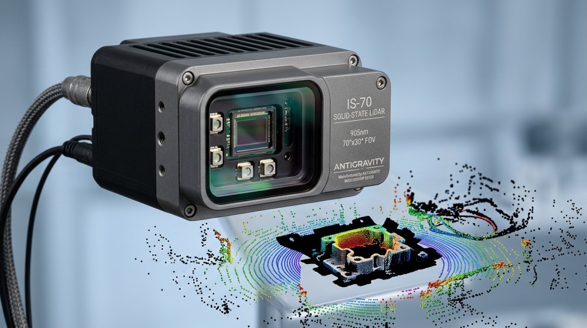
In hard-tech procurement, field of view is often treated like a headline metric. A sensor with 120° horizontal coverage may appear more capable than one with 70° or 90°. Yet any serious lidar field of view comparison must consider what happens to angular resolution, effective range, and usable point density when the same optical and processing budget is stretched across a wider scene.
For information researchers and enterprise decision-makers, the core issue is not marketing breadth but engineering sufficiency. In AGV, AMR, UAV, industrial perimeter sensing, and edge AI deployments, the best configuration is usually the one that matches the operational risk zone within a defined range such as 5–15 m, 20–50 m, or 80–200 m, rather than the one with the largest possible viewing angle.
A wider field of view can backfire in at least 3 ways: fewer points per degree, more irrelevant scene capture, and heavier processing demand on embedded compute. In practice, that means small obstacles can be represented by fewer returns, false positives can rise in cluttered environments, and thermal or power budgets at the edge can tighten during continuous operation over 8–24 hour duty cycles.
This is exactly where TechStat Vanguard’s engineering-first method matters. TSV examines parameters as interacting constraints, not isolated claims. In Sensors & Edge AI evaluations, field of view only becomes meaningful when read together with point cloud density, anti-interference behavior, scan architecture, latency window, and the workload pushed into downstream perception software.
What decision-makers should compare instead of viewing angle alone
A useful LiDAR comparison should separate coverage from detection quality. Buyers who skip that step often discover late in validation that wide-angle sensing reduced the consistency of object extraction. That creates avoidable rework in integration, mounting geometry, and software tuning during the next 2–6 weeks of system verification.
- Coverage zone: horizontal and vertical field of view matched to the actual hazard envelope, aisle width, flight corridor, or approach path.
- Detection granularity: whether the sensor keeps adequate point returns on small targets at the intended stand-off distance.
- Environmental robustness: lidar sunlight interference resistance, reflectivity tolerance, dust performance, and behavior under mixed indoor-outdoor transitions.
- Compute burden: the processing, memory, and thermal load created by a larger scene and denser perception pipeline.
For operators, this comparison also changes daily usability. A sensor that “sees more” but triggers more nuisance alarms or demands frequent recalibration can be less valuable than a narrower sensor optimized for the actual route, speed, and obstacle profile.
Where wider coverage backfires in real applications
The penalty of excessive field of view depends on application geometry. In warehouse AGV or AMR navigation, a very wide horizontal scan may capture shelving, pallets, cross-traffic, and reflective surfaces outside the path-planning relevance zone. That extra information is not free. It increases segmentation complexity and can reduce the stability of obstacle classification in dense logistics spaces.
In outdoor robotics and smart infrastructure, wider field coverage can expose the sensor to more direct solar angles, glints, and background clutter. When teams are already concerned about lidar sunlight interference resistance, increasing the visible scene can enlarge the interference opportunity set. This does not mean wide FoV is wrong; it means anti-interference validation must be tied to mounting angle, time-of-day exposure, and expected target reflectivity.
For UAV mapping or low-altitude autonomy, broad coverage may improve situational awareness, but only if the platform can absorb the added data load. On airframes with limited onboard compute and tight power margins, a larger FoV may compete with flight control, imaging payloads, and communication modules. In some deployments, 10%–20% extra perception load can force compromises elsewhere in the avionics stack.
In industrial safety zones, a wider vertical or diagonal view may also introduce blind trust. Teams assume broader sensing equals safer sensing, but safety integrity depends on detectable object size, response latency, and consistent zone behavior under vibration, dust, and ambient light swings. A sensor that captures more area but with lower confidence on edge targets can be harder to certify into a stable operating process.
Application-by-application judgment matters
The table below shows how wider coverage can help or hurt depending on task profile, distance window, and compute constraints. This is the practical lens TSV recommends for a procurement review.
The pattern is clear: wider FoV is usually justified when the scene has true lateral uncertainty. It becomes inefficient when the operational corridor is narrow, highly structured, or already known. That distinction helps buyers avoid paying for scene breadth that later undermines precision.
How field of view changes point cloud density, interference risk, and edge workload
A central mistake in lidar field of view comparison is assuming that wider optical coverage preserves the same quality of spatial representation. If the scan budget is fixed, distributing measurements across more degrees typically reduces returns per angular segment. For solid state lidar point cloud density, that can mean fewer effective hits on slim obstacles, partially occluded objects, or low-reflectivity surfaces.
This trade-off becomes more visible at longer ranges. A target that looks stable at 10 m may appear sparse at 30 m or fragmented at 50 m if point allocation is too thin. For operators, the outcome is simple: apparent detection instability. For procurement teams, the consequence is harder benchmarking, because headline FoV masks the real issue of usable data quality at the exact stand-off distance that the workflow requires.
Lidar sunlight interference resistance should also be read alongside field of view. A broader scan can expose the receiver and perception stack to a larger set of high-brightness angles, reflective facades, polished metal, and glass transitions. In edge deployments moving from warehouse docks to outdoor yards, interference events often cluster at these transitions rather than in steady-state indoor use.
Then there is edge compute. Wider coverage creates more spatial data to filter, classify, and fuse. If the platform relies on embedded SOCs, industrial gateways, or vehicle controllers with finite memory and thermal headroom, perception latency can drift upward. Even a shift from a 30 ms to a 60 ms perception cycle can matter in faster mobile platforms or in short stopping-distance scenarios.
A practical engineering comparison checklist
Instead of comparing only degrees of view, engineering teams should review the combined parameter stack below. This is especially useful when screening an agv lidar sensor supplier or validating a solid-state design against deployment conditions.
This table is valuable because it links parameter language to deployment consequences. That is how TSV approaches benchmarking: not “which sensor looks larger on paper,” but “which parameter combination remains reliable in the actual workflow.”
Three hidden trade-offs many teams discover too late
- A broad field of view can reduce effective detail where small hazards matter most, especially if obstacle size is modest and route speed is not low.
- The wider the scene, the more software filtering is usually needed, which may add engineering effort during integration and tuning.
- Single-sensor breadth is not always cheaper than a multi-sensor layout optimized by task zone, because compute, revalidation, and nuisance behavior carry real lifecycle cost.
How to choose the right FoV for AGV, robotics, and industrial procurement
For procurement teams, the practical question is not “Which LiDAR has the biggest field of view?” but “Which sensor achieves reliable detection with acceptable compute cost in our geometry?” A disciplined selection process usually takes 4 steps and can prevent expensive redesign after pilot deployment.
First, define the detection envelope. That includes operating speed, stop distance, target size, route width, mounting height, and environmental transitions. In many AGV projects, the relevant zone is narrower than assumed. When that happens, a moderate FoV with stronger point cloud concentration often outperforms a broader scan.
Second, test under interference, not only under ideal indoor lighting. If your route passes loading docks, skylights, reflective floor markings, or outdoor segments, evaluate lidar sunlight interference resistance over repeated cycles. A 2–3 day validation under changing light can reveal more than a static lab demo.
Third, compare system cost, not sensor price alone. A lower-cost wide FoV sensor may require more compute, more tuning hours, or more false-alarm management. By contrast, a better-matched FoV may reduce deployment friction, shorten commissioning time, and stabilize operations sooner.
A procurement checklist for evaluating an AGV LiDAR sensor supplier
- Request parameter sheets that show FoV together with range behavior, angular resolution, and point cloud characteristics, not FoV in isolation.
- Ask for validation guidance on sunlight, shiny surfaces, dark materials, and transition zones common to your facility.
- Confirm interface compatibility, latency expectations, and data throughput limits with your controller or edge gateway.
- Define a 3-stage acceptance path: bench test, pilot route test, and sustained operation test over at least one representative duty cycle.
- Review delivery realities such as sample lead time, integration support window, firmware update policy, and spare-part planning.
This process aligns with TSV’s broader mission across robotics, sensors, UAV systems, and precision industrial infrastructure: reducing trial-and-error cost by moving the conversation from vague superiority claims to testable engineering thresholds.
When narrower or segmented coverage is the better alternative
There are many cases where narrower coverage is not a compromise but the correct design decision. In straight corridors, machine approach lanes, dock guidance, and perimeter sectors with predictable intrusion paths, a focused detection zone often yields cleaner data and easier integration. Some teams also use segmented sensing, assigning different sensors or regions to different tasks rather than forcing one device to do everything.
That alternative can improve maintainability. Instead of one wide sensor capturing every possible scene element, you create 2 or more task-defined sensing zones: forward navigation, side awareness, or docking precision. The result is often better fault isolation and more transparent system tuning.
Common misconceptions, implementation risks, and what to ask before buying
One common misconception is that wider coverage automatically lowers hardware count and therefore reduces project cost. That can be true in some static monitoring cases, but in mobile robotics and edge AI systems the hidden cost often moves into compute, software complexity, and field debugging. Procurement teams should model total deployment effort across at least 3 layers: hardware, integration, and operations.
Another misconception is that point cloud density is a secondary metric. In reality, solid state lidar point cloud density is often the difference between stable object representation and intermittent detection, especially for irregular obstacles, pallet forks, low-profile objects, or partial edge targets. If the use case depends on fine geometry, density is not optional.
A third risk is overgeneralizing from a demo. A sensor may perform well in a clean aisle over 30 minutes and still struggle across 2 shifts in mixed light, dust, reflective packaging, and route congestion. Validation should include representative speed, duty cycle, and ambient conditions, not only controlled demonstrations.
For decision-makers balancing budget and reliability, the best question is often: where does additional coverage stop generating actionable detection value? Once that threshold is identified, the field of view comparison becomes a business tool instead of a marketing trap.
FAQ
How do I choose between wide FoV and higher point cloud density?
Start from the task geometry. If the scene is narrow, structured, or predictable, higher effective density in the required zone is often more valuable than wider coverage. If the scene has frequent lateral uncertainty, intersections, or open-space maneuvering, wider FoV may help. The decision should be checked at the real operating range, not only in near-field demos.
What should I prioritize for outdoor LiDAR use?
Prioritize lidar sunlight interference resistance, reflectivity tolerance, and stable performance through indoor-outdoor transitions. Wide FoV can be useful outdoors, but it should be validated against actual solar exposure angles, reflective surfaces, and target materials. If possible, test across several times of day rather than a single short session.
Is a single wide-angle LiDAR always better than multiple narrower sensors?
No. A single wide-angle unit may simplify mechanical layout, but it can also increase irrelevant data capture and processing burden. Multiple narrower sensors can sometimes provide cleaner task zoning, better redundancy, and easier troubleshooting. The right choice depends on route geometry, controller capacity, maintenance strategy, and acceptable integration complexity.
What is the typical supplier evaluation timeline?
A practical B2B evaluation often runs in 2–6 weeks: initial parameter review, sample or demo testing, route-level validation, and procurement alignment. More complex projects involving UAV payload integration, industrial certification review, or software adaptation may take longer. The key is to lock the acceptance criteria before testing starts.
Why work with TSV when evaluating LiDAR coverage trade-offs
TechStat Vanguard exists for teams that need engineering truth, not inflated language. In lidar field of view comparison, that means we help translate broad claims into structured evaluation logic: coverage versus point density, anti-interference behavior versus environment, and hardware convenience versus total system burden.
Our value is especially relevant to R&D engineers, procurement leads, CTOs, and operations teams working across robotics, UAV systems, Sensors & Edge AI, and advanced industrial infrastructure. We focus on parameter relationships that actually affect deployment outcomes, supplier qualification speed, and long-term maintainability.
If you are comparing solid state lidar point cloud density, reviewing lidar sunlight interference resistance, or screening an agv lidar sensor supplier, contact TSV for a more rigorous evaluation framework. We can support parameter confirmation, selection logic, application-fit analysis, delivery cycle review, integration risk mapping, and requirement drafting for your spec sheet or sourcing process.
Bring your target range, route geometry, mounting constraints, environmental conditions, compute budget, and procurement timeline. We will help you identify which FoV range is justified, what trade-offs need testing first, which acceptance checkpoints belong in a pilot, and where a narrower or segmented architecture may deliver better value.
Search News
Hot Articles
- Carbon Fiber StructuresHow to Specify Aerospace Carbon Fiber Assemblies for Lightweight, Load-Bearing PartsJul 11, 2026
- Machine VisionXiaomi, Alibaba DAMO Academy Drive Open-Source Robotics Model Ecosystem, Lowering Algorithm Development Barriers for Overseas SMEs Adopting Chinese Robotics SolutionsMar 30, 2026
- Cobots & ArmsShanxi 'AI+' Conference Showcases Embodied Intelligence with Multinational Buyer Engagement: Key Industry ImplicationsMar 30, 2026
Popular Tags
Recommended News
 Jul 11, 2026How to Specify Aerospace Carbon Fiber Assemblies for Lightweight, Load-Bearing PartsAerospace carbon fiber assemblies: learn how to specify laminate design, load data, joining methods, and inspection controls for lighter, reliable load-bearing aerospace parts.Elena Rostova (UAV Systems Researcher)
 Mar 30, 2026Xiaomi, Alibaba DAMO Academy Drive Open-Source Robotics Model Ecosystem, Lowering Algorithm Development Barriers for Overseas SMEs Adopting Chinese Robotics SolutionsXiaomi & Alibaba DAMO Academy's open-source robotics models lower algorithm barriers for global SMEs. Boost efficiency in manufacturing, logistics & smart retail with ROS 2 compatible solutions.TSV Data Lab
 Mar 30, 2026Shanxi 'AI+' Conference Showcases Embodied Intelligence with Multinational Buyer Engagement: Key Industry ImplicationsShanxi 'AI+' Conference highlights embodied intelligence with Tesla, Ubtech & Jiantao showcasing multimodal robotics. 40+ global buyers validated tech on-site, creating new B2B channels for industrial automation & AI solutions.Chen Wei (Automation Lead Engineer)
 Mar 30, 2026Zhongguancun Unveils 6G Integrated Sensing-Computing-Intelligence Platform to Empower Embodied Robots for Global Industrial ApplicationsZhongguancun's new 6G platform revolutionizes industrial robotics with <10ms latency, empowering global automotive, logistics & port automation. Discover how this tech boosts China's smart manufacturing exports.TSV Data Lab
 Mar 30, 2026Mech-Mind Tianjin Embodied Intelligence R&D and Production Base Goes Live, Cutting Delivery Time by 20%–30% for Global Customized AMR+Vision SolutionsMech-Mind's Tianjin AMR+Vision production base cuts delivery time by 20%-30% for欧美 & Latin American markets. Discover how this PLd-certified facility accelerates customized robotics solutions for smart manufacturing and logistics.Chen Wei (Automation Lead Engineer)
 Mar 30, 2026Boao Forum Reveals 'Co-evolution of Big and Small Brains' Trend in Humanoid Robots, China's Embodied Intelligence Accelerates Adaptation to Overseas Manufacturing Service ScenariosDiscover how China's humanoid robots, featuring 'Co-evolution of Big and Small Brains,' are revolutionizing global manufacturing. Learn about Embodied Tian Gong 3.0's ISO compliance and overseas deployment at Boao Forum 2026.Chen Wei (Automation Lead Engineer)
 Mar 30, 2026China Railway Industrial Secures Patent for Embodied Robotics in Material Handling, Boosting High-Precision Delivery Capabilities for Overseas Infrastructure and Manufacturing ProjectsChina Railway Industrial's new patent for embodied robotics in material handling boosts high-precision delivery for global infrastructure & manufacturing. Discover how this innovation enhances logistics accuracy in automotive, rail transit & EPC projects.Chen Wei (Automation Lead Engineer)
 Oct 21, 2026China’s Industrial Robot Exports Near RMB 10 Billion in First Nine Months of 2026China’s industrial robot exports neared RMB 10 billion in January–September 2026, with value rising faster than volume. Explore the data and what it could mean for suppliers.Chen Wei (Automation Lead Engineer)
 Oct 21, 2026Low-Latency Industrial Data Processing: Pricing and Key Cost DriversExplore industrial data latency price drivers, from edge hardware to integration and support. Learn how to compare quotes, verify performance, and avoid unnecessary costs.TSV Data Lab
 Oct 20, 2026KUKA Launches iiQKA.AI Vision to Simplify Industrial Image ProcessingKUKA iiQKA.AI Vision simplifies industrial image processing with controller-based 2D and 3D vision. Explore drag-and-drop setup for vision-guided automation.TSV Data Lab
 Oct 20, 2026Smart Industrial Edge Devices: Key Criteria for Legacy PLC IntegrationChoose smart industrial edge devices for legacy PLC integration. Discover key criteria for compatibility, data quality, security, and reliable collection without disrupting control.TSV Data Lab
 Oct 19, 2026Choosing a Radar Sensor by Application: Range, Resolution, and Field of ViewSimplify radar sensor application based product selection. Compare range, resolution, and field of view to avoid blind spots and choose with confidence. Explore the guide.TSV Data Lab
 Oct 18, 2026Comparing Material Options for Procurement: Specs, Costs, and Supply RisksExplore procurement oriented technical content on material options, specs, costs, and supply risks. Compare alternatives to cut hidden expenses and make confident sourcing decisions.Dr. Marcus Vance
 Oct 17, 20265-Axis CNC Positioning Accuracy: How to Interpret ISO 230-2 Test ResultsAssess 5 axis CNC machining positioning accuracy with ISO 230-2. Learn to interpret repeatability, reversal error, and test conditions to compare suppliers and make confident acceptance decisions.Dr. Marcus Vance
 Oct 16, 2026Choosing a Rugged Edge AI Box Supplier: Thermal Tests and Lifecycle SupportChoose a rugged edge AI box supplier with proven thermal performance and reliable lifecycle support. Discover the tests and commitments to verify before you buy.TSV Data Lab
 Oct 15, 2026R&D Cost Reduction Services: How to Evaluate Fees, Savings, and ROIEvaluate R&D cost reduction services with confidence. Compare fees, verify savings, and calculate ROI without compromising performance. Discover how to choose a provider that delivers real value.Chen Wei (Automation Lead Engineer)
 Oct 21, 2026How Should You Balance Cobot Payload Against Reach?Explore cobot payload versus reach to choose the right robot. Learn how tooling, load limits, workspace, and cycle time affect performance—and avoid costly selection mistakes.Chen Wei (Automation Lead Engineer)
 Oct 20, 2026How Do You Measure Industrial IoT Gateway Latency Under Load?Measure industrial IoT gateway latency under load with reliable timestamps, realistic traffic, and tail-latency analysis. Discover how to expose bottlenecks and choose the right gateway.TSV Data Lab
 Oct 19, 2026How Do You Verify That Precision Machined Parts Meet Tolerances?Master precision machining tolerance verification with the right tools, datum setups, and acceptance rules. Learn how to validate parts confidently and reduce costly inspection errors.Dr. Marcus Vance
 Oct 18, 2026What Should an AS9100 Machining Supplier Checklist Include?Build an AS9100 machining supplier checklist that verifies capability, traceability, inspection, and outsourced processes. Discover what to check before approving your next aerospace supplier.Dr. Marcus Vance
 Oct 17, 2026How Should You Interpret Industrial Robot Repeatability Specs?Decode industrial robot repeatability specifications, understand ISO 9283 test conditions, and avoid costly selection mistakes. Learn how to verify performance for your process.Chen Wei (Automation Lead Engineer)
 Oct 16, 2026How Can You Fairly Compare MTBF Across Industrial Servo Motors?Make a fair industrial servo motor MTBF comparison with matched operating profiles, failure criteria, and confidence bounds. Discover how to assess reliability beyond advertised numbers.Chen Wei (Automation Lead Engineer)
 Oct 15, 2026How Should You Compare TechStat Vanguard 5-Axis CNC Tolerances?TechStat Vanguard 5-axis CNC tolerance comparison: learn how to verify part accuracy, assess inspection evidence, and choose suppliers that reliably meet your drawing requirements.Dr. Marcus Vance
 Oct 14, 2026Drone Frame Composites: Carbon Fiber vs. Fiberglass for Weight and StiffnessExplore drone structural materials composites: compare carbon fiber and fiberglass for weight, stiffness, cost, and antenna compatibility. Find the right material for your drone frame.Elena Rostova (UAV Systems Researcher)