How to Choose Collaborative Robots for Electronics Assembly by Task, Reach, and Payload
Publication Date
author
Selecting collaborative robots for electronics assembly sounds simple until real process limits show up. Reach, payload, and speed matter, but they only matter in context.
For electronics lines, the better question is not “Which cobot is strongest?” It is “Which robot fits the exact task, workstation, and quality window without creating new validation risk?”
That is the standard TechStat Vanguard applies across hard-tech benchmarking. Parameters matter more than slogans. In electronics assembly, repeatability, ESD behavior, mounting flexibility, and actual tool load usually decide success faster than brochure claims.
Start with the task before the robot
The first filter for collaborative robots for electronics assembly should always be task definition. If the task is unclear, every later comparison becomes noisy and expensive.
A PCB screwdriving cell, a conformal coating station, and a tray-to-fixture pick-and-place cell may all use cobots, but they need very different motion profiles and tool integration logic.
A simple engineering screen helps cut through that noise:
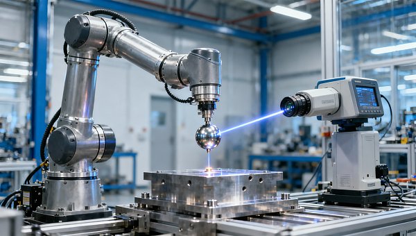
Use the image above as a mental model. Start from the workpiece and process path, then move outward to arm envelope, payload, cabling, and cell constraints.
- Define the exact operation first, including handling, insertion, fastening, dispensing, or inspection, because each motion pattern changes ideal arm stiffness, speed limits, and end-effector integration needs.
- Map the true part presentation method, such as tray, reel, pallet, or conveyor, since feed orientation often drives wrist access and collision risk more than nominal reach.
- Measure takt time by sub-step, not by total cycle only, because electronics assembly often loses throughput in settle time, vision correction, and tool confirmation.
- Separate process-critical accuracy from transport motion, because a cobot may move parts reliably yet still miss insertion windows once connector tolerance stacks tighten.
Why task mapping changes model selection
For light pick-and-place, payload may stay below 1 kg. Yet the better model may still be a higher-rated arm if the wrist must carry vision, a compliant gripper, and routed cables.
By contrast, fine insertion of board-level connectors often depends less on payload and more on repeatability under slow approach, stable force behavior, and low vibration after deceleration.
Check reach in the real workstation, not on paper
Reach is one of the most misunderstood filters when comparing collaborative robots for electronics assembly. Catalog reach only shows the maximum kinematic envelope. It does not show useful reach under safe tooling angles.
In electronics assembly, useful reach usually shrinks because of feeder racks, guarding edges, vision brackets, solder fume extraction, and fixture height offsets.
- Model the working envelope with the actual tool length attached, because long screwdrivers, dispensers, and grippers can create wrist singularities near deep or narrow fixtures.
- Check vertical clearance as carefully as horizontal reach, since electronics benches often stack feeders, ESD mats, and fixtures that reduce safe approach angles.
- Verify reach at the furthest repeatable process point, not the furthest touch point, because end-of-stroke positions often lose precision and practical cycle speed.
- Review mounting options early, including table, wall, or inverted placement, because a different base position may solve reach limits without moving to a larger cobot.
A short workstation example
A benchtop screwdriving cell may look reachable with a 900 mm arm. Then the feeder bowl shifts left, the controller cabinet takes floor space, and the wrist loses the angle needed for the rear fastener.
At that point, a slightly longer arm or overhead mount can outperform a heavier robot. This is why TSV-style evaluation starts with usable geometry, not broad marketing labels.
Treat payload as a dynamic number
Payload is rarely just the part weight. For collaborative robots for electronics assembly, the real load includes gripper mass, brackets, tool changers, vacuum generators, cable drag, and moment load at the wrist.
This matters because many electronics tasks run fast, stop often, and need stable path recovery. A robot near its practical load limit may still work, but cycle consistency can degrade.
- Calculate total moving mass at the flange, then add cable and hose effects, because published payload alone does not capture dynamic wrist loading.
- Leave margin for acceleration and future tooling changes, because electronics cells often evolve from simple handling to inspection or fastening within one validation cycle.
- Check torque and moment limits, not payload only, since a light but long end effector can overload the wrist faster than a compact heavier tool.
Do not skip the hidden electronics constraints
This is where many comparisons of collaborative robots for electronics assembly go off track. The robot may fit the motion task, yet still fail the line environment.
Electronics assembly adds constraints that are easy to underestimate: ESD sensitivity, clean cable routing, low particle generation, vision lighting stability, and software handshake reliability with testers or MES layers.
- Confirm ESD compatibility for the robot, tooling, and workstation interfaces, because one weak grounding path can turn a valid automation cell into a latent quality risk.
- Review cable routing around the wrist and forearm, since exposed loops can snag fixtures, block cameras, or introduce repeatability drift during fine motion.
- Check controller communication options early, including fieldbus and API behavior, because integration delays often come from data handshake issues rather than mechanics.
- Test vision and lighting interaction with robot surfaces and motion, because glare, shadowing, and vibration can quietly lower inspection confidence.
Where small oversights become large delays
A cobot may pass a demo using manual tray loading, then struggle once inline barcode verification, torque traceability, and reject handling are added. The mechanical choice was not wrong, but the system definition was incomplete.
That is why TSV emphasizes engineering truth through data. The useful spec is the validated spec inside the real process chain.
Match the robot to common electronics assembly situations
Small-part pick and place
For trays, reels, and compact fixtures, low payload is normal, but smooth motion and stable vision correction matter more. Favor compact arms with good repeatability and clean integration with vacuum tooling.
Watch approach angles near dense fixtures. If wrist access is awkward, theoretical throughput disappears into micro-pauses and recovery moves.
Screwdriving and fastening
This task often pushes teams toward higher payload models, but the bigger factor is stiffness under tool reaction and positional stability over repeated cycles.
Check screwdriver mass, bit extension length, torque reaction control, and traceability interface. A robot that merely reaches the fastener is not enough.
Dispensing, solder support, or test handling
These tasks need path consistency and easy process synchronization. Reach and payload still matter, but software integration, path smoothing, and maintenance access often decide long-term usability.
If the cell must switch product variants often, prioritize fast recipe management and simple re-teach workflows alongside the core robot specifications.
Use a short decision path before final validation
A practical decision path keeps collaborative robots for electronics assembly selection grounded in measurable fit instead of generic preference.
- Rank candidate robots by task fit first, then screen for reach, payload, repeatability, and interface compatibility, because process success starts with function, not brand familiarity.
- Build a simple risk matrix for ESD, cycle time, tooling mass, and integration effort, because hidden engineering gaps usually appear before purchase, not after installation.
- Request validation using your own part geometry and path data, since demo wins with generic objects say little about real electronics assembly performance.
- Compare maintainability, spare support, and software openness alongside hardware specs, because the best cobot choice should remain practical after the first deployment phase.
In the end, choosing collaborative robots for electronics assembly is less about chasing the biggest reach or payload number. It is about matching the robot to the exact motion, tool, environment, and data requirements of the cell.
A clear task definition, realistic workstation model, and honest load calculation will usually narrow the field quickly. From there, ESD behavior, integration detail, and repeatable process performance become the real decision makers.
If the next step is model comparison, start with one workstation, one tool stack, and one cycle target. That approach produces cleaner data, faster validation, and a much stronger decision than any headline spec sheet.
Search News
Hot Articles
- Carbon Fiber StructuresHow to Specify Aerospace Carbon Fiber Assemblies for Lightweight, Load-Bearing PartsJul 11, 2026
- Machine VisionXiaomi, Alibaba DAMO Academy Drive Open-Source Robotics Model Ecosystem, Lowering Algorithm Development Barriers for Overseas SMEs Adopting Chinese Robotics SolutionsMar 30, 2026
- Cobots & ArmsShanxi 'AI+' Conference Showcases Embodied Intelligence with Multinational Buyer Engagement: Key Industry ImplicationsMar 30, 2026
Popular Tags
Recommended News
 Jul 11, 2026How to Specify Aerospace Carbon Fiber Assemblies for Lightweight, Load-Bearing PartsAerospace carbon fiber assemblies: learn how to specify laminate design, load data, joining methods, and inspection controls for lighter, reliable load-bearing aerospace parts.Elena Rostova (UAV Systems Researcher)
 Mar 30, 2026Xiaomi, Alibaba DAMO Academy Drive Open-Source Robotics Model Ecosystem, Lowering Algorithm Development Barriers for Overseas SMEs Adopting Chinese Robotics SolutionsXiaomi & Alibaba DAMO Academy's open-source robotics models lower algorithm barriers for global SMEs. Boost efficiency in manufacturing, logistics & smart retail with ROS 2 compatible solutions.TSV Data Lab
 Mar 30, 2026Shanxi 'AI+' Conference Showcases Embodied Intelligence with Multinational Buyer Engagement: Key Industry ImplicationsShanxi 'AI+' Conference highlights embodied intelligence with Tesla, Ubtech & Jiantao showcasing multimodal robotics. 40+ global buyers validated tech on-site, creating new B2B channels for industrial automation & AI solutions.Chen Wei (Automation Lead Engineer)
 Mar 30, 2026Zhongguancun Unveils 6G Integrated Sensing-Computing-Intelligence Platform to Empower Embodied Robots for Global Industrial ApplicationsZhongguancun's new 6G platform revolutionizes industrial robotics with <10ms latency, empowering global automotive, logistics & port automation. Discover how this tech boosts China's smart manufacturing exports.TSV Data Lab
 Mar 30, 2026Mech-Mind Tianjin Embodied Intelligence R&D and Production Base Goes Live, Cutting Delivery Time by 20%–30% for Global Customized AMR+Vision SolutionsMech-Mind's Tianjin AMR+Vision production base cuts delivery time by 20%-30% for欧美 & Latin American markets. Discover how this PLd-certified facility accelerates customized robotics solutions for smart manufacturing and logistics.Chen Wei (Automation Lead Engineer)
 Mar 30, 2026Boao Forum Reveals 'Co-evolution of Big and Small Brains' Trend in Humanoid Robots, China's Embodied Intelligence Accelerates Adaptation to Overseas Manufacturing Service ScenariosDiscover how China's humanoid robots, featuring 'Co-evolution of Big and Small Brains,' are revolutionizing global manufacturing. Learn about Embodied Tian Gong 3.0's ISO compliance and overseas deployment at Boao Forum 2026.Chen Wei (Automation Lead Engineer)
 Mar 30, 2026China Railway Industrial Secures Patent for Embodied Robotics in Material Handling, Boosting High-Precision Delivery Capabilities for Overseas Infrastructure and Manufacturing ProjectsChina Railway Industrial's new patent for embodied robotics in material handling boosts high-precision delivery for global infrastructure & manufacturing. Discover how this innovation enhances logistics accuracy in automotive, rail transit & EPC projects.Chen Wei (Automation Lead Engineer)
 Oct 21, 2026China’s Industrial Robot Exports Near RMB 10 Billion in First Nine Months of 2026China’s industrial robot exports neared RMB 10 billion in January–September 2026, with value rising faster than volume. Explore the data and what it could mean for suppliers.Chen Wei (Automation Lead Engineer)
 Oct 21, 2026Low-Latency Industrial Data Processing: Pricing and Key Cost DriversExplore industrial data latency price drivers, from edge hardware to integration and support. Learn how to compare quotes, verify performance, and avoid unnecessary costs.TSV Data Lab
 Oct 20, 2026KUKA Launches iiQKA.AI Vision to Simplify Industrial Image ProcessingKUKA iiQKA.AI Vision simplifies industrial image processing with controller-based 2D and 3D vision. Explore drag-and-drop setup for vision-guided automation.TSV Data Lab
 Oct 20, 2026Smart Industrial Edge Devices: Key Criteria for Legacy PLC IntegrationChoose smart industrial edge devices for legacy PLC integration. Discover key criteria for compatibility, data quality, security, and reliable collection without disrupting control.TSV Data Lab
 Oct 19, 2026Choosing a Radar Sensor by Application: Range, Resolution, and Field of ViewSimplify radar sensor application based product selection. Compare range, resolution, and field of view to avoid blind spots and choose with confidence. Explore the guide.TSV Data Lab
 Oct 18, 2026Comparing Material Options for Procurement: Specs, Costs, and Supply RisksExplore procurement oriented technical content on material options, specs, costs, and supply risks. Compare alternatives to cut hidden expenses and make confident sourcing decisions.Dr. Marcus Vance
 Oct 17, 20265-Axis CNC Positioning Accuracy: How to Interpret ISO 230-2 Test ResultsAssess 5 axis CNC machining positioning accuracy with ISO 230-2. Learn to interpret repeatability, reversal error, and test conditions to compare suppliers and make confident acceptance decisions.Dr. Marcus Vance
 Oct 16, 2026Choosing a Rugged Edge AI Box Supplier: Thermal Tests and Lifecycle SupportChoose a rugged edge AI box supplier with proven thermal performance and reliable lifecycle support. Discover the tests and commitments to verify before you buy.TSV Data Lab
 Oct 15, 2026R&D Cost Reduction Services: How to Evaluate Fees, Savings, and ROIEvaluate R&D cost reduction services with confidence. Compare fees, verify savings, and calculate ROI without compromising performance. Discover how to choose a provider that delivers real value.Chen Wei (Automation Lead Engineer)
 Oct 20, 2026How Do You Measure Industrial IoT Gateway Latency Under Load?Measure industrial IoT gateway latency under load with reliable timestamps, realistic traffic, and tail-latency analysis. Discover how to expose bottlenecks and choose the right gateway.TSV Data Lab
 Oct 19, 2026How Do You Verify That Precision Machined Parts Meet Tolerances?Master precision machining tolerance verification with the right tools, datum setups, and acceptance rules. Learn how to validate parts confidently and reduce costly inspection errors.Dr. Marcus Vance
 Oct 18, 2026What Should an AS9100 Machining Supplier Checklist Include?Build an AS9100 machining supplier checklist that verifies capability, traceability, inspection, and outsourced processes. Discover what to check before approving your next aerospace supplier.Dr. Marcus Vance
 Oct 17, 2026How Should You Interpret Industrial Robot Repeatability Specs?Decode industrial robot repeatability specifications, understand ISO 9283 test conditions, and avoid costly selection mistakes. Learn how to verify performance for your process.Chen Wei (Automation Lead Engineer)
 Oct 16, 2026How Can You Fairly Compare MTBF Across Industrial Servo Motors?Make a fair industrial servo motor MTBF comparison with matched operating profiles, failure criteria, and confidence bounds. Discover how to assess reliability beyond advertised numbers.Chen Wei (Automation Lead Engineer)
 Oct 15, 2026How Should You Compare TechStat Vanguard 5-Axis CNC Tolerances?TechStat Vanguard 5-axis CNC tolerance comparison: learn how to verify part accuracy, assess inspection evidence, and choose suppliers that reliably meet your drawing requirements.Dr. Marcus Vance
 Oct 14, 2026Drone Frame Composites: Carbon Fiber vs. Fiberglass for Weight and StiffnessExplore drone structural materials composites: compare carbon fiber and fiberglass for weight, stiffness, cost, and antenna compatibility. Find the right material for your drone frame.Elena Rostova (UAV Systems Researcher)
 Oct 13, 2026Smart Cameras vs. PC-Based Machine Vision: Which Fits High-Speed Inspection?This industrial product comparison for machine vision weighs smart cameras vs. PC-based systems on latency, throughput, and cost. Discover your best fit for high-speed inspection.TSV Data Lab