Navigation Fault Tolerance Standards for AMRs: What Safety Teams Must Verify
Publication Date
author
Navigation fault tolerance is not a single certification item that can be confirmed by checking whether an AMR carries a CE mark, a safety laser scanner certificate, or a supplier’s safety claim. It is a system-level capability: when localization becomes unreliable, sensors are obscured, communications fail, or an obstacle appears in an unexpected location, the robot must detect that its assumptions are no longer valid and transition to a safe state before hazardous motion occurs.
For an AMR operating around pedestrians, forklifts, racks, dock doors, conveyors, and variable floor conditions, the critical question is not whether it can navigate under nominal conditions. It is whether its navigation architecture fails predictably, detects degradation early enough, and maintains separation from people and equipment during the transition. The evidence required for that judgment must connect the risk assessment, safety functions, sensing limits, control logic, validation tests, and operating controls.
There is no standalone “navigation fault tolerance” certificate
Standards governing industrial mobile robots establish safety requirements and risk-reduction principles, but they do not create a universal pass/fail certificate for navigation resilience in every facility. A compliant AMR may still be unsuitable for a specific site if its perception, localization, or operating assumptions are not validated against local hazards.
ISO 3691-4, Industrial trucks — Safety requirements and verification — Part 4: Driverless industrial trucks and their systems, is the central international reference for driverless industrial trucks, including many AMR and AGV applications. It addresses safety-related functions, protective fields, operating modes, stopping behavior, and system-level requirements. In the United States, ANSI/RIA R15.08 provides a related framework for industrial mobile robot safety, including requirements for manufacturers and for integration and use.
Neither standard removes the need for a documented application-specific risk assessment. ISO 12100 remains fundamental because risk depends on the actual intended use, reasonably foreseeable misuse, environment, payload, traffic interactions, and accessible hazardous zones. Navigation performance only becomes meaningful when evaluated against these real operating conditions.
The practical implication is important: a declaration that the robot “uses LiDAR SLAM,” “has obstacle avoidance,” or “can reroute autonomously” is not proof of safety. These are navigation features. Safety acceptance requires evidence that faults affecting those features are either controlled by a safety-rated architecture or bounded by validated operating restrictions.
Separate navigation performance from safety functions
AMR reviews often become confused because navigation and safety sensing may share physical sensors, maps, computing resources, or data streams. Their functions must nevertheless be separated conceptually and, where required by the safety design, functionally.
Navigation determines where the robot believes it is, where it should travel, and how it plans a path. It may rely on SLAM, reflectors, natural features, wheel odometry, inertial measurement units, cameras, 2D or 3D LiDAR, QR markers, or a combination of these inputs. Navigation can be highly capable while still being non-safety-rated.
Safety functions determine whether motion is permitted and how hazards are controlled. Typical functions include protective stop on intrusion into a safety field, speed reduction when people approach, prevention of motion outside a defined zone, emergency stop, safe braking, and prevention of restart after a protective stop until defined reset conditions are met. The safety-related parts of the control system should be designed and validated using an appropriate framework, commonly ISO 13849-1 and ISO 13849-2, or IEC 62061 where applicable.
A safety team should insist on a clear answer to a basic architecture question: if the navigation stack is wrong, delayed, frozen, or unavailable, what independent mechanism prevents unsafe motion? If the answer is merely that the robot will “recalculate its route,” the response is incomplete. Recalculation can be useful for availability, but it is not a substitute for a defined safety function.
Fault conditions that must be explicitly addressed
Fault tolerance should be evaluated against credible failure modes rather than treated as a generic product attribute. The relevant conditions vary by site, but several categories require direct examination.
Localization loss, drift, and map inconsistency
Localization failure is not limited to a complete “lost robot” event. More difficult cases include gradual pose drift, incorrect heading estimates, repeated map matching to similar rack aisles, unrecognized environmental changes, and sudden jumps in reported position. A robot that continues moving while its confidence estimate declines can create risk even when it has not declared a formal fault.
Verification should establish how localization confidence is calculated, what thresholds trigger restricted operation or stopping, and whether the threshold is linked to stopping distance and available clearance. The robot should not be allowed to continue normal-speed travel merely because a position estimate remains numerically available. Safety documentation should explain the response to loss of map match, conflicting sensor inputs, implausible odometry, and navigation software restart.
Safety sensor degradation and obstruction
Protective LiDAR scanners, safety-rated cameras, bumpers, and other safeguarding devices can be affected by dust, stretch wrap, condensation, direct sunlight, reflective surfaces, contamination, vibration, or physical misalignment. A sensor can remain powered and report no obvious hardware error while its effective detection capability has been reduced.
The required evidence is not simply a component certificate. The review should confirm how sensor obstruction, window contamination, field configuration errors, wiring faults, communication loss, and scanner mounting displacement are detected. It should also identify the resulting safe state. Depending on the risk assessment, the response may be a protective stop, a controlled stop, prevention of autonomous restart, or a restricted operating mode with separate controls. The response must be appropriate to the hazard; it cannot be inferred from the presence of a safety scanner.
Dynamic obstacles and atypical objects
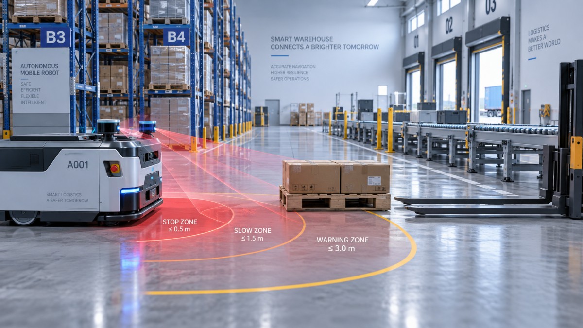
Protective-field performance should not be confused with general object-recognition performance. Safety scanners are designed to detect intrusion into a configured protective field, but the effective safety envelope depends on mounting height, field geometry, robot speed, braking performance, floor condition, load projection, and the object’s location relative to the sensing plane.
Low-profile items, overhanging loads, open forklift tines, transparent materials, suspended objects, and objects outside the scanner plane may create hazards that a standard horizontal scan cannot address. A site with pallet overhang or conveyors at variable elevations may require additional detection methods, mechanical segregation, speed restrictions, or route design changes. These conditions should appear in the hazard log, not only in informal operating guidance.
Communication and infrastructure loss
Wireless connectivity is often important for fleet dispatch, map updates, remote supervision, and traffic coordination. It should not be assumed that loss of Wi-Fi, cloud connectivity, or fleet-manager communication automatically creates an immediate safety hazard. The safety consequence depends on what the robot continues to do without that connection.
Key questions include whether the AMR can continue safely to a defined stopping point, whether it can enter intersections without coordination, whether remote commands can remain active after link degradation, and whether map or mission updates can occur while the vehicle is in motion. The expected degraded mode should be documented. A robot that relies on network coordination to avoid vehicle conflicts needs a particularly clear loss-of-communication strategy.
Power, braking, and control-system faults
Navigation resilience is irrelevant if a fault produces uncontrolled coast-down, delayed braking, or an unsafe restart. The safety file should identify the stop categories used, the braking assumptions used to calculate protective fields, battery-related behavior, safe torque-off arrangements where used, and fault detection for drive control. Stopping-distance validation must reflect the actual vehicle configuration, including payload, tire condition, floor friction, slope, and any attached cart or load-handling device.
What a credible validation package should contain
A satisfactory validation package is traceable. It links each identified hazard to a risk-reduction measure, then shows how the measure was verified under stated conditions. A product brochure, component certificate, or generic factory acceptance record cannot establish this link on its own.
Validation records should state test conditions precisely. “Obstacle detection passed” is too vague to be meaningful. A usable record identifies vehicle speed, load state, sensing configuration, obstacle position, ambient conditions where relevant, software and map version, braking state, expected stop response, measured result, and acceptance criterion. These details allow later incidents, layout changes, and software updates to be evaluated against a known baseline.
Stopping distance is a system calculation, not a scanner specification
Protective-field sizing must account for the total distance traveled from the moment a hazard enters the field until the AMR reaches a safe stop. This includes sensor response time, safety controller processing time, communication or interface delays within the safety chain, brake response time, and mechanical stopping distance. A margin is also needed for measurement uncertainty and expected operating variation.
ISO 13855 provides principles for positioning safeguards with respect to approach speeds, and its logic is useful when evaluating protective separation. However, applying a formula without validating the actual machine behavior can create false confidence. Braking behavior can change with payload, tire wear, floor contamination, battery state, gradients, and towing arrangements. Any change that affects the real stopping distance can affect the adequacy of configured safety fields.
This is especially significant where an AMR carries pallets extending beyond the chassis, has a raised load, or tows carts. The protective envelope must cover the actual hazard geometry, not just the base vehicle footprint shown in a navigation interface.
Restart behavior deserves the same scrutiny as stopping behavior
A protective stop is only half of the safety function. The system must also prevent hazardous automatic restart. ISO 13850 addresses emergency-stop function principles, while reset and restart requirements should be considered within the broader safety-control design and risk assessment.
After a protective field is interrupted, an AMR may need to remain stopped until the field is clear and a defined restart condition has been met. The appropriate reset arrangement depends on visibility, route design, and the possibility that a person remains in a hazardous area outside the sensor’s current field of view. Automatic resumption may be acceptable in some low-risk, well-controlled situations, but it should never be treated as a default convenience feature.
The review should distinguish among emergency stop, protective stop, operational stop, controlled stop for navigation uncertainty, and loss-of-communication stop. They may have different triggers, braking characteristics, reset permissions, and recovery procedures. Combining all of them under the label “the robot stops” conceals important safety differences.
Operational controls determine whether validated safety remains valid
Navigation fault tolerance can degrade after commissioning if the facility changes faster than the safety documentation. Rack reconfiguration, temporary staging, new reflective surfaces, floor repairs, altered pedestrian routes, different packaging materials, or a revised fleet-management rule can change the assumptions behind a safe deployment.
A controlled management-of-change process should apply to route maps, virtual zones, speed limits, safety field sets, payload envelopes, attachments, software versions, and charging or handoff locations. Changes should be classified by whether they alter hazards, safety-function performance, or stopping-distance assumptions. A seemingly minor map adjustment can become safety-relevant if it moves the AMR closer to a pedestrian crossing, a drop edge, or a congested work cell.
Periodic inspection also needs to go beyond checking that the AMR powers on and completes missions. It should include sensor cleanliness and alignment, bumper condition, wheel and brake condition, emergency-stop operation, warning devices, protective-field response, configuration integrity, and review of fault logs. Repeated localization warnings, protective stops in the same zone, or unplanned manual recoveries may indicate a changing risk condition rather than isolated operational inconvenience.
The approval decision should be based on bounded behavior under fault
The strongest evidence of navigation fault tolerance is not an assertion that the AMR can handle every abnormal event. It is proof that the system recognizes the limits of its perception and localization, reduces or stops motion within validated boundaries, prevents unsafe restart, and records the event for investigation.
ISO 3691-4 and related safety-control standards provide the necessary framework, but safe deployment depends on translating those requirements into site-specific acceptance criteria. The approval record should make clear what the AMR is permitted to do, under which environmental and operational conditions, what faults it can detect, what safe state follows each fault, and what changes invalidate the original validation.
Where those boundaries are explicit and tested, navigation resilience becomes a verifiable safety property rather than a marketing description.
Search News
Hot Articles
- Carbon Fiber StructuresHow to Specify Aerospace Carbon Fiber Assemblies for Lightweight, Load-Bearing PartsJul 11, 2026
- Machine VisionXiaomi, Alibaba DAMO Academy Drive Open-Source Robotics Model Ecosystem, Lowering Algorithm Development Barriers for Overseas SMEs Adopting Chinese Robotics SolutionsMar 30, 2026
- Cobots & ArmsShanxi 'AI+' Conference Showcases Embodied Intelligence with Multinational Buyer Engagement: Key Industry ImplicationsMar 30, 2026
Popular Tags
Recommended News
 Jul 11, 2026How to Specify Aerospace Carbon Fiber Assemblies for Lightweight, Load-Bearing PartsAerospace carbon fiber assemblies: learn how to specify laminate design, load data, joining methods, and inspection controls for lighter, reliable load-bearing aerospace parts.Elena Rostova (UAV Systems Researcher)
 Mar 30, 2026Xiaomi, Alibaba DAMO Academy Drive Open-Source Robotics Model Ecosystem, Lowering Algorithm Development Barriers for Overseas SMEs Adopting Chinese Robotics SolutionsXiaomi & Alibaba DAMO Academy's open-source robotics models lower algorithm barriers for global SMEs. Boost efficiency in manufacturing, logistics & smart retail with ROS 2 compatible solutions.TSV Data Lab
 Mar 30, 2026Shanxi 'AI+' Conference Showcases Embodied Intelligence with Multinational Buyer Engagement: Key Industry ImplicationsShanxi 'AI+' Conference highlights embodied intelligence with Tesla, Ubtech & Jiantao showcasing multimodal robotics. 40+ global buyers validated tech on-site, creating new B2B channels for industrial automation & AI solutions.Chen Wei (Automation Lead Engineer)
 Mar 30, 2026Zhongguancun Unveils 6G Integrated Sensing-Computing-Intelligence Platform to Empower Embodied Robots for Global Industrial ApplicationsZhongguancun's new 6G platform revolutionizes industrial robotics with <10ms latency, empowering global automotive, logistics & port automation. Discover how this tech boosts China's smart manufacturing exports.TSV Data Lab
 Mar 30, 2026Mech-Mind Tianjin Embodied Intelligence R&D and Production Base Goes Live, Cutting Delivery Time by 20%–30% for Global Customized AMR+Vision SolutionsMech-Mind's Tianjin AMR+Vision production base cuts delivery time by 20%-30% for欧美 & Latin American markets. Discover how this PLd-certified facility accelerates customized robotics solutions for smart manufacturing and logistics.Chen Wei (Automation Lead Engineer)
 Mar 30, 2026Boao Forum Reveals 'Co-evolution of Big and Small Brains' Trend in Humanoid Robots, China's Embodied Intelligence Accelerates Adaptation to Overseas Manufacturing Service ScenariosDiscover how China's humanoid robots, featuring 'Co-evolution of Big and Small Brains,' are revolutionizing global manufacturing. Learn about Embodied Tian Gong 3.0's ISO compliance and overseas deployment at Boao Forum 2026.Chen Wei (Automation Lead Engineer)
 Mar 30, 2026China Railway Industrial Secures Patent for Embodied Robotics in Material Handling, Boosting High-Precision Delivery Capabilities for Overseas Infrastructure and Manufacturing ProjectsChina Railway Industrial's new patent for embodied robotics in material handling boosts high-precision delivery for global infrastructure & manufacturing. Discover how this innovation enhances logistics accuracy in automotive, rail transit & EPC projects.Chen Wei (Automation Lead Engineer)
 Oct 06, 2026Navigation Fault Tolerance Standards for AMRs: What Safety Teams Must VerifyNavigation fault tolerance standards: learn what AMR safety teams must verify, from localization loss and sensor faults to stopping distance, safe restart, and site-specific validation.Chen Wei (Automation Lead Engineer)
 Oct 05, 2026Calculating Edge Computing Total Cost of Ownership Across Distributed SitesEdge computing ownership cost explained: calculate deployment, energy, connectivity, security, remote support, and refresh costs across distributed sites.TSV Data Lab
 Oct 04, 2026CAD/CAM Benchmarking in the GCC: What Manufacturers Should Ask a ConsultantCAD CAM benchmark consultant GCC guide: learn the key questions manufacturers should ask to validate post-processors, workflows, machine performance, and production risk.Victor Lin (Chief Software Architect)
 Oct 03, 2026Selecting Automotive Radar Sensor Modules for ADAS Range, Resolution, and IntegrationAutomotive radar sensor module selection guide for ADAS: compare range, resolution, field of view, latency, and integration to build safer, reliable vehicle systems.TSV Data Lab
 Oct 02, 2026How to Qualify Machined Parts Suppliers for Hard Tech ProgramsHard tech supply chain machined parts demand rigorous supplier qualification. Learn how to assess capability, traceability, quality controls, and delivery resilience.Dr. Marcus Vance
 Oct 01, 2026How to Select an Outdoor Security Radar Sensor for Perimeter Detection?Outdoor security radar sensor selection guide: compare range, accuracy, false-alarm control, integration, and field testing for reliable perimeter detection.TSV Data Lab
 Sep 30, 2026How to Evaluate Solid-State LiDAR Hardware for Outdoor Autonomous VehiclesSolid state LiDAR hardware evaluation guide for outdoor autonomous vehicles—compare range, point-cloud quality, environmental resilience, integration, and safety.TSV Data Lab
 Sep 29, 2026ISO 9283 Repeatability: How to Evaluate Cobot Positioning PerformanceISO 9283 cobot repeatability explained: learn how payload, reach, approach direction, and test conditions affect positioning performance and cell capability.Chen Wei (Automation Lead Engineer)
 Oct 05, 2026What Causes Machine Vision Systems to Miss Small Defects?What causes machine vision systems to miss small defects? Discover how lighting, optics, motion, and AI thresholds affect detection—and prevent costly escapes.TSV Data Lab
 Oct 04, 2026How Should You Compare 5-Axis CNC Machine Accuracy Claims?How do I compare 5-axis CNC machine accuracy claims? Learn how to assess standards, thermal stability, TCP accuracy, and real-world test evidence.Dr. Marcus Vance
 Oct 03, 2026Is Edge Computing Necessary for Real-Time Quality Inspection?Is industrial edge computing necessary for real-time quality inspection? Explore how latency, data volume, reliability, and control integration shape the right architecture.TSV Data Lab
 Oct 02, 2026What Documents Prove a Precision Machining Supplier Can Hold Tolerance?What documents prove a precision machining supplier can hold tolerance? Explore certificates, FAI reports, calibration, SPC, and traceability evidence to qualify suppliers with confidence.Dr. Marcus Vance
 Oct 01, 2026Can a Machining Supplier Meet Aerospace Fatigue Testing Requirements?Can a machining supplier meet aerospace fatigue testing requirements? Learn the traceability, process control, and test evidence needed for reliable aerospace parts.Dr. Marcus Vance
 Sep 30, 2026Which Industrial Robot Specifications Matter for High-Precision Assembly?Which industrial robot specifications matter most for high-precision assembly? Explore repeatability, accuracy, stiffness, vibration, calibration, and force control for reliable yields.Chen Wei (Automation Lead Engineer)
 Sep 29, 2026How Do You Verify Servo Motor Torque Under Continuous Load?How do I verify servo motor torque under continuous load? Learn RMS torque checks, torque-speed limits, thermal derating, and real-machine testing.Chen Wei (Automation Lead Engineer)
 Oct 02, 2026ZD330 Software Configuration: Verifying Cut-List Import Before PurchaseZD330 software and machine configuration: verify cut-list imports, data mapping, labels, and workflow before purchase to reduce errors and choose with confidence.Victor Lin (Chief Software Architect)
 Sep 28, 2026Spindle Runout Measurement in Germany: DIN Standards, Methods, and Acceptance LimitsSpindle runout measurement Germany: explore DIN standards, proven methods, acceptance limits, and audit-ready practices for reliable machining quality.Dr. Marcus Vance