What Causes Machine Vision Systems to Miss Small Defects?
Publication Date
author
A machine vision system can miss small defects even when the camera has ample resolution on paper. The failure usually occurs because the defect does not produce a stable, distinguishable signal at the sensor under real production conditions. A scratch may reflect like the surrounding surface, a chip may occupy too few useful pixels, a moving part may blur, or an inspection algorithm may reject a borderline indication to avoid excessive false alarms.
For manufacturers inspecting coatings, machined edges, electronics, seals, printed codes, or precision assemblies, this is more than a tuning inconvenience. A missed defect is a false accept: the system has classified a nonconforming part as good. Before replacing cameras or adding more AI, teams should determine where the visual signal is being lost: at illumination, optics, motion, image acquisition, image processing, or the definition of the defect itself.
Resolution Is Necessary, but It Does Not Define Detectability
The most common assumption is that a higher-resolution camera will find smaller defects. Resolution matters, but pixel count alone does not establish inspection capability.
A defect must span enough pixels to be separated from normal texture, sensor noise, compression artifacts, and variation in the part itself. If a 30-micron pit maps to one or two pixels, the system may register a brightness change, but it cannot reliably determine whether that change is a pit, a dust particle, a surface grain, or an imaging fluctuation. Raising camera resolution can increase the number of pixels on the feature, yet the result may still be weak if the optical contrast is poor.
The calculation also depends on field of view. A camera inspecting an entire wide panel distributes its pixels across a large area; a camera inspecting a narrow weld bead can allocate the same sensor resolution across a much smaller area. This is why an inspection specification should begin with the smallest defect that must be detected, the required field of view, and the minimum number of usable pixels across that defect. “High resolution” is not a meaningful acceptance criterion without those three conditions.
There is a further limitation: sensor pixels do not see objects directly. They receive light after it has passed through a lens, interacted with the target surface, and been affected by exposure settings and motion. If any of those stages suppresses the defect signal, additional pixels merely produce a sharper image of an ambiguous surface.
Lighting Often Determines Whether the Defect Exists in the Image
Small defects are frequently lighting problems disguised as camera problems. The relevant question is not whether the part looks clear to a human observer under general room lighting. It is whether the illumination geometry makes the defect visibly different from an acceptable area in a repeatable image.
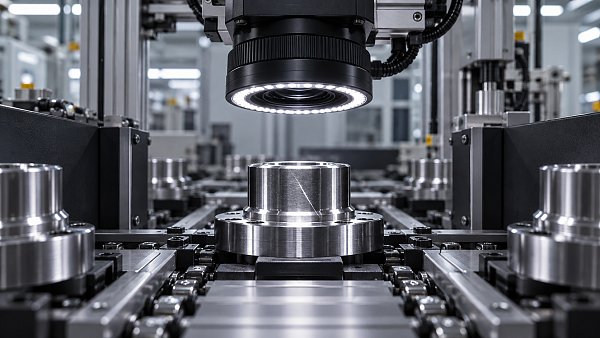
A shallow scratch on polished metal may vanish under diffuse frontal illumination because both the damaged and undamaged surface return similar light to the camera. The same scratch can become highly visible under low-angle dark-field lighting, where its edges scatter light into the lens. Conversely, a glossy raised feature may create distracting reflections under directional lighting and inspect more reliably under a diffuse dome or coaxial arrangement.
Surface type changes the lighting decision. Transparent films, black rubber, textured castings, reflective machined components, printed packaging, and solder joints can each require a different approach. Lighting wavelength can matter as well. A colored mark that has little contrast in visible white light may separate better under a selected monochromatic wavelength; infrared or ultraviolet approaches may help in specialised material conditions, though they bring their own safety, optics, and validation requirements.
Uniformity matters as much as contrast. A lighting system that produces a bright region at one end of the field and a dark region at the other forces inspection software to use broad thresholds. Those broader thresholds can let weak defects disappear. Variations caused by LED aging, heat, contamination on protective windows, or changes in working distance can steadily reduce detection performance after a system has been commissioned.
For a suspected miss, examine image samples of both known-good and known-defective parts under the exact installed lighting condition. Compare the grayscale or color separation in the defect area, not just the visual appeal of the full image. If the defect does not consistently stand apart before image processing begins, algorithm adjustments will have limited value.
Lens Selection Can Remove Detail Before the Camera Receives It
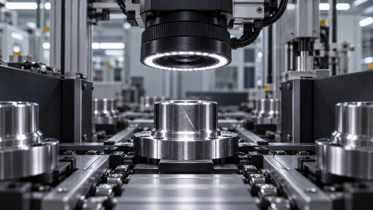
The lens is often treated as a passive accessory, yet it sets the usable sharpness, contrast, depth of field, and geometric fidelity of the inspection. A lens that is acceptable for presence/absence checking may be inadequate for small-defect detection.
One issue is optical resolution. Every lens has a practical limit on the detail and contrast it can transfer to the sensor. Pairing a high-pixel-count camera with a lens that cannot resolve the required feature creates an expensive mismatch. Fine defects may appear soft or merge into adjacent texture, even though the pixel scale suggests they should be detectable.
Aperture selection creates a trade-off between light and depth of field. Opening the aperture admits more light and can support a shorter exposure, but it reduces depth of field. On parts with height variation, warped surfaces, uneven fixturing, or multiple inspection planes, a small defect may sit outside the sharp focal range. Closing the aperture increases depth of field but may require more illumination or longer exposure, both of which can introduce other problems.
Working distance and viewing angle also affect consistency. If the part position changes slightly and the lens has significant perspective distortion, the feature may shift, scale, or warp in the image. Telecentric optics can reduce magnification changes caused by depth variation and are useful in some dimensional and edge-inspection tasks, but they are not a universal cure. They add cost, impose constraints on field of view and lighting layout, and still require suitable contrast.
Lens cleanliness should not be dismissed as routine maintenance. Oil mist, dust, residue, and scratches on a lens cover can scatter light and lower local contrast. In a system designed near its detection limit, a small optical degradation can change a marginal inspection into an unreliable one.
Motion, Vibration, and Timing Turn Small Features into Noise
At production speed, a vision system must capture the defect while the part, camera, lighting, and trigger sequence remain sufficiently stable. Small defects are especially vulnerable because even modest blur can erase their edges.
Exposure time should be assessed against actual part velocity, not nominal conveyor speed. Speed changes during starts, stops, indexing, or load transitions can make a camera setting that works during trials fail during normal operation. A short exposure freezes motion but demands enough light. A longer exposure improves brightness but may smear fine scratches, print defects, or edge chips across several pixels.
Mechanical vibration can cause similar degradation, particularly where cameras are mounted on machine frames, conveyor structures, or robot cells. It may not be obvious in a single captured image. Reviewing a burst of images can reveal frame-to-frame movement, focus shifts, or changing reflections. Vibration also affects lighting geometry, which can make a defect visible in one frame and nearly invisible in the next.
Trigger timing deserves the same attention. If a sensor triggers a camera before the part reaches the intended inspection zone, or if encoder feedback does not match actual motion, the region of interest may be misplaced. Systems that inspect continuously moving material need robust synchronization between transport position, line speed, illumination pulse, and acquisition. A correctly configured algorithm cannot detect a defect outside its inspected area.
Part Variation Can Be Larger Than the Defect Signal
Machine vision succeeds when the visual difference between acceptable and unacceptable conditions is larger and more consistent than normal variation. In many applications, that condition is not met at first.
Material texture, lot-to-lot color differences, changing surface finish, mold-release residue, oil films, print density shifts, and fixture variation can all look like defects. To avoid rejecting too many good parts, a system may be tuned conservatively. The consequence is predictable: subtle genuine defects are also accepted.
This is particularly difficult for cosmetic inspection. A defect definition such as “minor scratch” or “surface blemish” may be clear to a quality reviewer who can rotate the part under changing light, but it is not yet a machine-inspectable criterion. The engineering team needs to translate it into observable conditions: length, width, orientation, contrast, location, surface zone, and acceptable severity. Some defects may only be visible from a specific angle or under a specific illumination arrangement. Others may be functionally significant but visually indistinguishable from allowable texture.
Reference images must reflect the real range of good production. A narrow sample set can make an algorithm appear accurate during development and unstable after deployment. Likewise, defect samples should include the smallest relevant defects, not only obvious reject examples. Training or tuning around clear defects produces an optimistic result that does not represent the inspection threshold.
Thresholds and AI Models Can Be Tuned to Miss Defects Deliberately
Every automated inspection balances false accepts against false rejects. Raising sensitivity may expose more small defects, but it can also reject parts because of harmless surface variation, lighting noise, or debris. Reducing nuisance rejects can therefore create a hidden increase in missed defects.
Rule-based systems often fail through overly broad grayscale, color, edge, area, or shape thresholds. A minimum-area filter may remove small true defects because it was added to suppress dust. A region mask may exclude a critical edge because of part-position variation. Image smoothing may reduce random noise while also weakening the tiny high-frequency feature that indicates damage.
AI-based systems introduce different failure modes. A model trained mostly on normal parts may learn that subtle defects are normal texture. A classifier trained on defect categories that are visually dramatic may have poor sensitivity to borderline conditions. An anomaly-detection model can be useful where defect types are diverse, but its performance depends heavily on whether the training images represent genuine normal variation.
Model confidence should not be confused with detection reliability. A highly confident decision can still be wrong when the input image has poor contrast, shifted lighting, an unseen surface condition, or a defect type absent from the training set. Inspection teams should validate performance using controlled challenge samples and production-representative variation, then monitor drift after commissioning.
Processing Capacity Can Cause Misses Even When Images Are Good
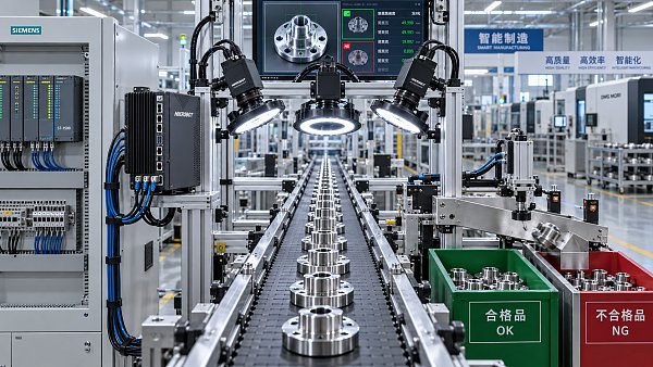
In high-speed inspection, the image can be captured correctly but never evaluated in time. Edge devices, industrial PCs, network links, storage policies, and PLC handshakes all affect whether an inspection result reaches the reject mechanism before the part leaves the rejection point.
Latency problems are sometimes misdiagnosed as detection failures. The software detects the defect, but the reject signal arrives too late, targets the wrong part, or is discarded when queues fill during peak throughput. Frame drops, skipped analysis jobs, and trigger overruns can have the same effect. A dashboard showing an acceptable average processing time does not rule this out; the important measure is the worst-case processing and communication path under operating load.
System design should account for the full sequence: image acquisition, transfer, preprocessing, inspection, decision, traceability record, output signal, and physical rejection. Where the process runs close to hardware capacity, a temporary spike in inference time or network congestion can produce intermittent escapes that are difficult to reproduce later.
A Practical Way to Diagnose Small-Defect Escapes
When a machine vision system misses a defect, changing many parameters at once usually delays the diagnosis. Start by separating visibility from classification and classification from actuation.
- Collect the original images for accepted defective parts, including trigger data, exposure settings, line speed, and part position where available.
- Check whether the defect is visually separable in the raw image. If it is absent or ambiguous, investigate lighting, optics, focus, motion, and part presentation before changing the algorithm.
- Measure the defect in pixels across multiple examples. Confirm that the smallest required defect has enough image support for a repeatable decision.
- Compare missed defects with accepted good parts that look similar. This identifies whether the problem is inadequate contrast or a threshold designed to suppress normal variation.
- Review the inspection region, trigger position, and reject timing to confirm that every relevant area is captured and every failed decision is acted upon.
- Retest after changes with a deliberately mixed sample set: good parts, borderline good parts, obvious rejects, and defects near the required detection limit.
The resulting specification should state more than camera model, megapixels, and nominal line speed. It should define the smallest detectable defect under stated surface, lighting, focus, motion, and positioning conditions. It should also identify the allowed false-reject rate, the response time required for rejection, and the process changes that require revalidation.
Small-defect inspection becomes dependable when it is treated as a controlled measurement problem rather than a camera purchase. The question is not whether the system can see a defect in a favorable demonstration image. It is whether the complete optical and processing chain can distinguish that defect from acceptable production variation, at the required rate, for every part that matters.
Search News
Hot Articles
- Carbon Fiber StructuresHow to Specify Aerospace Carbon Fiber Assemblies for Lightweight, Load-Bearing PartsJul 11, 2026
- Machine VisionXiaomi, Alibaba DAMO Academy Drive Open-Source Robotics Model Ecosystem, Lowering Algorithm Development Barriers for Overseas SMEs Adopting Chinese Robotics SolutionsMar 30, 2026
- Cobots & ArmsShanxi 'AI+' Conference Showcases Embodied Intelligence with Multinational Buyer Engagement: Key Industry ImplicationsMar 30, 2026
Popular Tags
Recommended News
 Jul 11, 2026How to Specify Aerospace Carbon Fiber Assemblies for Lightweight, Load-Bearing PartsAerospace carbon fiber assemblies: learn how to specify laminate design, load data, joining methods, and inspection controls for lighter, reliable load-bearing aerospace parts.Elena Rostova (UAV Systems Researcher)
 Mar 30, 2026Xiaomi, Alibaba DAMO Academy Drive Open-Source Robotics Model Ecosystem, Lowering Algorithm Development Barriers for Overseas SMEs Adopting Chinese Robotics SolutionsXiaomi & Alibaba DAMO Academy's open-source robotics models lower algorithm barriers for global SMEs. Boost efficiency in manufacturing, logistics & smart retail with ROS 2 compatible solutions.TSV Data Lab
 Mar 30, 2026Shanxi 'AI+' Conference Showcases Embodied Intelligence with Multinational Buyer Engagement: Key Industry ImplicationsShanxi 'AI+' Conference highlights embodied intelligence with Tesla, Ubtech & Jiantao showcasing multimodal robotics. 40+ global buyers validated tech on-site, creating new B2B channels for industrial automation & AI solutions.Chen Wei (Automation Lead Engineer)
 Mar 30, 2026Zhongguancun Unveils 6G Integrated Sensing-Computing-Intelligence Platform to Empower Embodied Robots for Global Industrial ApplicationsZhongguancun's new 6G platform revolutionizes industrial robotics with <10ms latency, empowering global automotive, logistics & port automation. Discover how this tech boosts China's smart manufacturing exports.TSV Data Lab
 Mar 30, 2026Mech-Mind Tianjin Embodied Intelligence R&D and Production Base Goes Live, Cutting Delivery Time by 20%–30% for Global Customized AMR+Vision SolutionsMech-Mind's Tianjin AMR+Vision production base cuts delivery time by 20%-30% for欧美 & Latin American markets. Discover how this PLd-certified facility accelerates customized robotics solutions for smart manufacturing and logistics.Chen Wei (Automation Lead Engineer)
 Mar 30, 2026Boao Forum Reveals 'Co-evolution of Big and Small Brains' Trend in Humanoid Robots, China's Embodied Intelligence Accelerates Adaptation to Overseas Manufacturing Service ScenariosDiscover how China's humanoid robots, featuring 'Co-evolution of Big and Small Brains,' are revolutionizing global manufacturing. Learn about Embodied Tian Gong 3.0's ISO compliance and overseas deployment at Boao Forum 2026.Chen Wei (Automation Lead Engineer)
 Mar 30, 2026China Railway Industrial Secures Patent for Embodied Robotics in Material Handling, Boosting High-Precision Delivery Capabilities for Overseas Infrastructure and Manufacturing ProjectsChina Railway Industrial's new patent for embodied robotics in material handling boosts high-precision delivery for global infrastructure & manufacturing. Discover how this innovation enhances logistics accuracy in automotive, rail transit & EPC projects.Chen Wei (Automation Lead Engineer)
 Oct 05, 2026Calculating Edge Computing Total Cost of Ownership Across Distributed SitesEdge computing ownership cost explained: calculate deployment, energy, connectivity, security, remote support, and refresh costs across distributed sites.TSV Data Lab
 Oct 04, 2026CAD/CAM Benchmarking in the GCC: What Manufacturers Should Ask a ConsultantCAD CAM benchmark consultant GCC guide: learn the key questions manufacturers should ask to validate post-processors, workflows, machine performance, and production risk.Victor Lin (Chief Software Architect)
 Oct 03, 2026Selecting Automotive Radar Sensor Modules for ADAS Range, Resolution, and IntegrationAutomotive radar sensor module selection guide for ADAS: compare range, resolution, field of view, latency, and integration to build safer, reliable vehicle systems.TSV Data Lab
 Oct 02, 2026How to Qualify Machined Parts Suppliers for Hard Tech ProgramsHard tech supply chain machined parts demand rigorous supplier qualification. Learn how to assess capability, traceability, quality controls, and delivery resilience.Dr. Marcus Vance
 Oct 01, 2026How to Select an Outdoor Security Radar Sensor for Perimeter Detection?Outdoor security radar sensor selection guide: compare range, accuracy, false-alarm control, integration, and field testing for reliable perimeter detection.TSV Data Lab
 Sep 30, 2026How to Evaluate Solid-State LiDAR Hardware for Outdoor Autonomous VehiclesSolid state LiDAR hardware evaluation guide for outdoor autonomous vehicles—compare range, point-cloud quality, environmental resilience, integration, and safety.TSV Data Lab
 Sep 29, 2026ISO 9283 Repeatability: How to Evaluate Cobot Positioning PerformanceISO 9283 cobot repeatability explained: learn how payload, reach, approach direction, and test conditions affect positioning performance and cell capability.Chen Wei (Automation Lead Engineer)
 Oct 05, 2026What Causes Machine Vision Systems to Miss Small Defects?What causes machine vision systems to miss small defects? Discover how lighting, optics, motion, and AI thresholds affect detection—and prevent costly escapes.TSV Data Lab
 Oct 04, 2026How Should You Compare 5-Axis CNC Machine Accuracy Claims?How do I compare 5-axis CNC machine accuracy claims? Learn how to assess standards, thermal stability, TCP accuracy, and real-world test evidence.Dr. Marcus Vance
 Oct 03, 2026Is Edge Computing Necessary for Real-Time Quality Inspection?Is industrial edge computing necessary for real-time quality inspection? Explore how latency, data volume, reliability, and control integration shape the right architecture.TSV Data Lab
 Oct 02, 2026What Documents Prove a Precision Machining Supplier Can Hold Tolerance?What documents prove a precision machining supplier can hold tolerance? Explore certificates, FAI reports, calibration, SPC, and traceability evidence to qualify suppliers with confidence.Dr. Marcus Vance
 Oct 01, 2026Can a Machining Supplier Meet Aerospace Fatigue Testing Requirements?Can a machining supplier meet aerospace fatigue testing requirements? Learn the traceability, process control, and test evidence needed for reliable aerospace parts.Dr. Marcus Vance
 Sep 30, 2026Which Industrial Robot Specifications Matter for High-Precision Assembly?Which industrial robot specifications matter most for high-precision assembly? Explore repeatability, accuracy, stiffness, vibration, calibration, and force control for reliable yields.Chen Wei (Automation Lead Engineer)
 Sep 29, 2026How Do You Verify Servo Motor Torque Under Continuous Load?How do I verify servo motor torque under continuous load? Learn RMS torque checks, torque-speed limits, thermal derating, and real-machine testing.Chen Wei (Automation Lead Engineer)
 Oct 02, 2026ZD330 Software Configuration: Verifying Cut-List Import Before PurchaseZD330 software and machine configuration: verify cut-list imports, data mapping, labels, and workflow before purchase to reduce errors and choose with confidence.Victor Lin (Chief Software Architect)
 Sep 28, 2026Spindle Runout Measurement in Germany: DIN Standards, Methods, and Acceptance LimitsSpindle runout measurement Germany: explore DIN standards, proven methods, acceptance limits, and audit-ready practices for reliable machining quality.Dr. Marcus Vance
 Sep 27, 2026How to Select Wall-Mount Edge Devices for Space-Constrained Factory NetworksWall mount edge devices for space-constrained factories: evaluate workload, thermal design, power resilience, cable access, and network reliability for smarter deployments.TSV Data Lab