How Should You Compare 5-Axis CNC Machine Accuracy Claims?
Publication Date
author
A brochure may state “±5 μm positioning accuracy,” while another machine lists “0.003 mm accuracy.” At first glance, the choice seems simple. In practice, those figures may describe different axes, different travel lengths, different temperatures, or entirely different test procedures. One may be a compensated linear-axis value measured over a short stroke; the other may reflect a broader acceptance test. Neither number is meaningful until its conditions are visible.
So, how do I compare 5-axis CNC machine accuracy claims? Begin by treating every claim as an engineering statement that needs context. Ask what was measured, how it was measured, on which configuration, under what thermal condition, and whether the result describes isolated axis behavior or the accuracy of an actual five-axis toolpath. For aerospace structures, medical components, turbine blades, and other high-complexity parts, that distinction can determine whether a machine shortens qualification or creates a long sequence of corrective work.
The goal is not to find the smallest headline number. It is to identify the machine whose demonstrated accuracy remains credible in the geometry, materials, cycle times, and environmental conditions your production program will demand.
Do not compare labels before comparing definitions
“Accuracy” is often used as a catch-all term. On a 5-axis machining center, it can refer to linear positioning accuracy, rotary-axis indexing error, repeatability, contouring performance, tool center point (TCP) behavior, or the dimensional result of a machined test part. These are related, but they are not interchangeable.
A linear axis can position very accurately during a laser measurement and still produce a poor five-axis surface if rotary-axis errors, pivot-point uncertainty, servo mismatch, thermal drift, or control transformations are not well managed. Conversely, a machine with a less dramatic published linear-axis figure may deliver highly stable parts because its kinematics, compensation routines, and thermal control are better integrated.
Before placing two specifications side by side, request the manufacturer’s exact definition for each claimed value. A useful comparison starts with a plain-language translation:
- Positioning accuracy: How close an axis comes to a commanded location.
- Repeatability: How consistently the axis returns to the same location from repeated moves.
- Bidirectional accuracy: Whether measurements include reversal effects such as backlash, hysteresis, and servo behavior.
- Rotary accuracy: How precisely a B-, C-, A-, or other rotary axis reaches an angular command.
- Volumetric or spatial accuracy: The combined behavior of multiple axes across the working volume.
- Machining accuracy: The result achieved on a defined workpiece, with a defined tool, program, material, and cutting condition.
If a supplier cannot explain which of these terms is being used, the specification is not yet ready for a procurement decision.
The first question: what standard and test method support the number?
A comparison becomes more reliable when both suppliers report results against the same recognized procedure. ISO 230 series methods are widely used for machine-tool geometric and positioning evaluation, while ISO 10791 addresses machining-center test conditions and performance categories. Depending on market and application, manufacturers may also refer to ASME-based methods or customer-specific acceptance protocols.
The standard name alone is not enough. Ask for the relevant section, test setup, instrument type, measurement length, number of target positions, approach direction, and uncertainty statement. A laser interferometer test of X-axis positioning over the full travel answers a legitimate question—but it does not validate simultaneous five-axis cutting.
For each published or quoted figure, obtain answers to these questions:
- Was the result measured at acceptance, after compensation, or during a demonstration?
- Did the test cover full axis travel or only a selected range?
- Was the axis measured in both directions?
- What ambient temperature and warm-up state applied?
- Was the machine unloaded, or was material actually being cut?
- For rotary axes, was error measured throughout the useful angular range?
- Was TCP calibration included and verified after movement through multiple orientations?
These details can feel tedious during an early supplier review. They are far less tedious than discovering, after installation, that a quoted result depended on a controlled showroom condition your production floor will never reproduce.
Separate axis accuracy from five-axis part accuracy
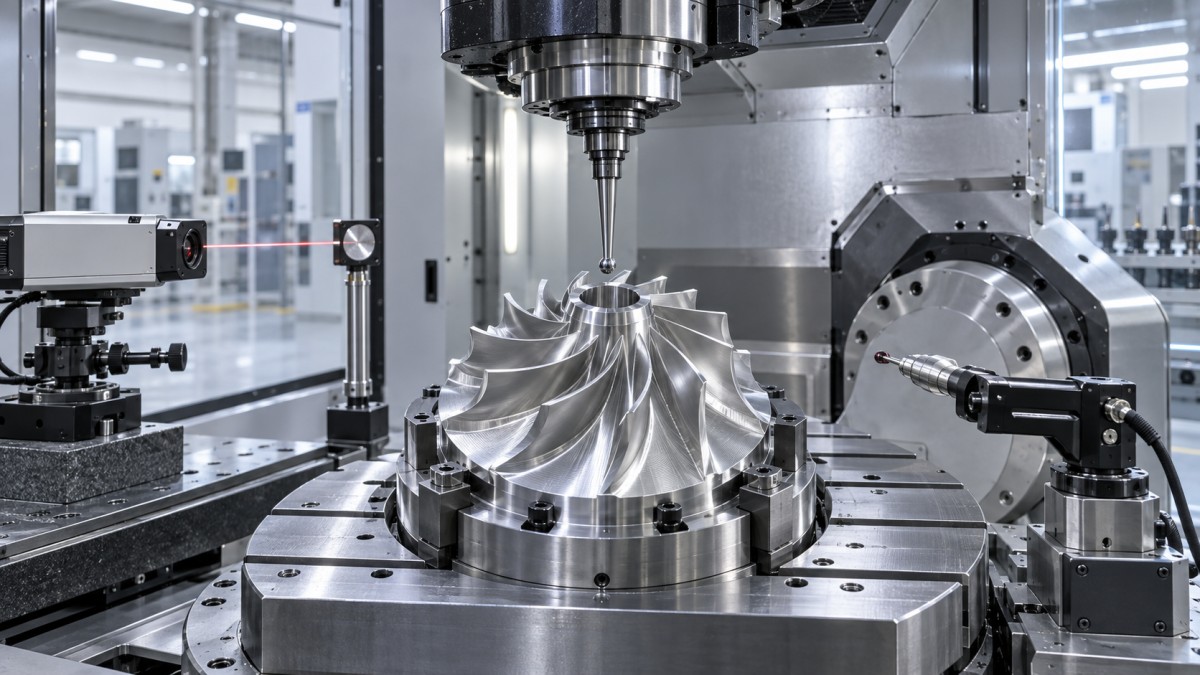
A 5-axis machine is a kinematic system, not simply a three-axis platform with two additional motions attached. When the tool or part rotates, small errors can be amplified at the cutting point. The effect grows with tool length, distance from the center of rotation, and the complexity of the programmed motion.
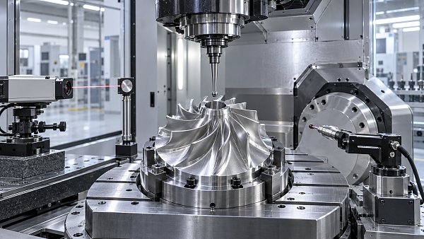
Imagine a long ball-nose tool finishing a blisk passage or a deep medical implant feature. A minute rotary-axis angular error may translate into a larger positional deviation at the tool tip. If the machine’s kinematic model does not accurately represent the relationship between linear and rotary axes, the surface may show blend errors, mismatched passes, or variation that ordinary axis-positioning figures never predicted.
This is why the most useful supplier discussion moves beyond “What is your X-axis accuracy?” to “How does the machine hold tool center point accuracy during simultaneous five-axis motion?” Ask whether the control supports kinematic calibration, how often it is checked, and whether compensation is maintained after transport, installation, collision recovery, or major service work.
A credible evaluation may include a geometric verification, a dynamic contouring test, and a representative cut. Together, these provide a more balanced view than any single brochure line.
Read repeatability with the same care as accuracy
In production, repeatability can be as important as absolute accuracy. A machine that is consistently offset may be corrected through probing, work offsets, or controlled compensation. A machine that drifts unpredictably from cycle to cycle is much harder to manage, especially when parts move between shifts, fixtures, or sister machines.
Do not assume a very small repeatability value guarantees the same dimensional result on a finished component. Repeatability may be measured under light, non-cutting conditions. Still, it tells you something essential about mechanical stability, feedback quality, control response, and the likelihood that a validated process can remain stable.
Review both unidirectional and bidirectional repeatability where available. Reversal behavior matters on features involving direction changes, adaptive toolpaths, interpolation, and complex surface finishing. For trunnion-style and swivel-head machines, rotary-axis reversal performance deserves particular scrutiny because many demanding programs repeatedly change orientation.
Thermal behavior is where many comparisons become unrealistic
Machine tools do not operate at a single temperature. Spindles accelerate and decelerate. Ballscrews, bearings, motors, hydraulic systems, and coolant circuits introduce heat. A machine that looks excellent after a controlled warm-up may behave differently after several hours of heavy roughing followed by precision finishing.
Ask suppliers how their accuracy claim accounts for thermal growth. Is there spindle and structure cooling? Are temperature sensors used in compensation? Does the control model adjust for predictable growth? More importantly, what evidence shows the system remains stable across a realistic duty cycle?
For a serious comparison, define your own thermal scenario. It might include a spindle warm-up, rough machining in titanium or Inconel, a dwell period, then a finishing operation on a critical feature. The exact sequence will vary, but the principle is consistent: evaluate the conditions that create risk in your shop, not only the conditions that create attractive documentation.
Also consider the environment around the machine. Changes in ambient temperature, direct sunlight, coolant temperature, foundation quality, and compressed-air stability can influence results. For a precision cell, the machine is only one part of the accuracy system.
A practical evidence package to request from every supplier
Rather than asking for “your best accuracy specification,” send the same evidence request to every candidate. This gives engineering, quality, and procurement teams a common basis for review.
Do not treat the table as paperwork for its own sake. It exposes whether two suppliers are discussing the same engineering reality. It also creates a record that can later inform factory acceptance testing (FAT), site acceptance testing (SAT), preventive maintenance, and capability investigations.
Make the test part resemble the risk in your actual component
A generic demonstration coupon can prove that a machine is operational. It may not prove that it can make your part. The closer the test geometry is to your failure modes, the more valuable the result becomes.
For impellers, blisks, and aerospace titanium components, include deep surfaces, changing tool vectors, thin walls, and areas that force long tool reach. For orthopedic or dental work, focus on freeform transitions, small radii, surface finish, and repeatability across multiple cycles. For prismatic aerospace parts, consider positional relationships between angled features, bores, datums, and machined faces after re-clamping or pallet transfer.
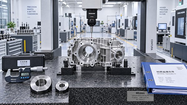
The test does not need to disclose sensitive design information. A simplified surrogate can reproduce the relevant kinematic challenge. What matters is that the inspection plan is agreed in advance: coordinate measuring machine strategy, datum scheme, sampling density, surface evaluation, and the temperature conditions under which the part is measured.
Watch for four common comparison errors
Comparing a compensated value to an uncompensated value. Compensation is not inherently suspicious; modern machine tools depend on it. The problem is comparing unlike conditions without disclosure. Ask what corrections were active and how they are maintained.
Using only a single-point claim. A favorable reading at one location says little about behavior across a large work envelope. Large aerospace parts and fixtures make this especially important.
Ignoring dynamics. High-feed simultaneous motion tests the interaction of drives, control algorithms, mechanical stiffness, and look-ahead behavior. Static positioning data cannot fully predict contour accuracy at production feed rates.
Assuming inspection can rescue an unstable process. Probing and post-process measurement are valuable safeguards, but they should not become a permanent substitute for predictable machine behavior. If every critical part requires extensive correction, the apparent purchase-price advantage may disappear in cycle time and quality cost.
Turn supplier claims into an acceptance plan
The strongest purchasing teams convert accuracy discussions into measurable acceptance criteria before the order is finalized. State the machine configuration, spindle, rotary table or head arrangement, control version, probing package, toolholder type, foundation requirements, and environmental assumptions. Then define which tests must be passed at FAT and which must be repeated after installation.
Include responsibilities for calibration records, instrument traceability, training, compensation recovery, and corrective action if results fall outside the agreed window. This is especially valuable in regulated or high-consequence work, where AS9100 or ISO 13485 quality systems demand disciplined evidence rather than verbal assurance.
TechStat Vanguard approaches machining benchmarks from this evidence-first perspective: parameters should be traceable to a test method, a machine state, and an application context. That discipline helps teams distinguish a useful capability claim from a number that merely looks competitive on a comparison sheet.
The better question is: accurate for what?
There is no universally “most accurate” 5-axis CNC machine in isolation. There is a machine that is accurate enough—and stable enough—for a defined part family, tolerance scheme, tool reach, material, throughput target, and production environment.
When reviewing a proposal, ask the question that brochure comparisons often avoid: Can this configuration repeatedly produce our critical features after warm-up, under realistic cutting loads, using a documented and maintainable calibration process? If the supplier can support the answer with transparent data, comparable test conditions, and a clear acceptance protocol, you have something far more useful than a headline specification. You have a basis for engineering confidence.
Search News
Hot Articles
- Carbon Fiber StructuresHow to Specify Aerospace Carbon Fiber Assemblies for Lightweight, Load-Bearing PartsJul 11, 2026
- Machine VisionXiaomi, Alibaba DAMO Academy Drive Open-Source Robotics Model Ecosystem, Lowering Algorithm Development Barriers for Overseas SMEs Adopting Chinese Robotics SolutionsMar 30, 2026
- Cobots & ArmsShanxi 'AI+' Conference Showcases Embodied Intelligence with Multinational Buyer Engagement: Key Industry ImplicationsMar 30, 2026
Popular Tags
Recommended News
 Jul 11, 2026How to Specify Aerospace Carbon Fiber Assemblies for Lightweight, Load-Bearing PartsAerospace carbon fiber assemblies: learn how to specify laminate design, load data, joining methods, and inspection controls for lighter, reliable load-bearing aerospace parts.Elena Rostova (UAV Systems Researcher)
 Mar 30, 2026Xiaomi, Alibaba DAMO Academy Drive Open-Source Robotics Model Ecosystem, Lowering Algorithm Development Barriers for Overseas SMEs Adopting Chinese Robotics SolutionsXiaomi & Alibaba DAMO Academy's open-source robotics models lower algorithm barriers for global SMEs. Boost efficiency in manufacturing, logistics & smart retail with ROS 2 compatible solutions.TSV Data Lab
 Mar 30, 2026Shanxi 'AI+' Conference Showcases Embodied Intelligence with Multinational Buyer Engagement: Key Industry ImplicationsShanxi 'AI+' Conference highlights embodied intelligence with Tesla, Ubtech & Jiantao showcasing multimodal robotics. 40+ global buyers validated tech on-site, creating new B2B channels for industrial automation & AI solutions.Chen Wei (Automation Lead Engineer)
 Mar 30, 2026Zhongguancun Unveils 6G Integrated Sensing-Computing-Intelligence Platform to Empower Embodied Robots for Global Industrial ApplicationsZhongguancun's new 6G platform revolutionizes industrial robotics with <10ms latency, empowering global automotive, logistics & port automation. Discover how this tech boosts China's smart manufacturing exports.TSV Data Lab
 Mar 30, 2026Mech-Mind Tianjin Embodied Intelligence R&D and Production Base Goes Live, Cutting Delivery Time by 20%–30% for Global Customized AMR+Vision SolutionsMech-Mind's Tianjin AMR+Vision production base cuts delivery time by 20%-30% for欧美 & Latin American markets. Discover how this PLd-certified facility accelerates customized robotics solutions for smart manufacturing and logistics.Chen Wei (Automation Lead Engineer)
 Mar 30, 2026Boao Forum Reveals 'Co-evolution of Big and Small Brains' Trend in Humanoid Robots, China's Embodied Intelligence Accelerates Adaptation to Overseas Manufacturing Service ScenariosDiscover how China's humanoid robots, featuring 'Co-evolution of Big and Small Brains,' are revolutionizing global manufacturing. Learn about Embodied Tian Gong 3.0's ISO compliance and overseas deployment at Boao Forum 2026.Chen Wei (Automation Lead Engineer)
 Mar 30, 2026China Railway Industrial Secures Patent for Embodied Robotics in Material Handling, Boosting High-Precision Delivery Capabilities for Overseas Infrastructure and Manufacturing ProjectsChina Railway Industrial's new patent for embodied robotics in material handling boosts high-precision delivery for global infrastructure & manufacturing. Discover how this innovation enhances logistics accuracy in automotive, rail transit & EPC projects.Chen Wei (Automation Lead Engineer)
 Oct 04, 2026CAD/CAM Benchmarking in the GCC: What Manufacturers Should Ask a ConsultantCAD CAM benchmark consultant GCC guide: learn the key questions manufacturers should ask to validate post-processors, workflows, machine performance, and production risk.Victor Lin (Chief Software Architect)
 Oct 03, 2026Selecting Automotive Radar Sensor Modules for ADAS Range, Resolution, and IntegrationAutomotive radar sensor module selection guide for ADAS: compare range, resolution, field of view, latency, and integration to build safer, reliable vehicle systems.TSV Data Lab
 Oct 02, 2026How to Qualify Machined Parts Suppliers for Hard Tech ProgramsHard tech supply chain machined parts demand rigorous supplier qualification. Learn how to assess capability, traceability, quality controls, and delivery resilience.Dr. Marcus Vance
 Oct 01, 2026How to Select an Outdoor Security Radar Sensor for Perimeter Detection?Outdoor security radar sensor selection guide: compare range, accuracy, false-alarm control, integration, and field testing for reliable perimeter detection.TSV Data Lab
 Sep 30, 2026How to Evaluate Solid-State LiDAR Hardware for Outdoor Autonomous VehiclesSolid state LiDAR hardware evaluation guide for outdoor autonomous vehicles—compare range, point-cloud quality, environmental resilience, integration, and safety.TSV Data Lab
 Sep 29, 2026ISO 9283 Repeatability: How to Evaluate Cobot Positioning PerformanceISO 9283 cobot repeatability explained: learn how payload, reach, approach direction, and test conditions affect positioning performance and cell capability.Chen Wei (Automation Lead Engineer)
 Oct 04, 2026How Should You Compare 5-Axis CNC Machine Accuracy Claims?How do I compare 5-axis CNC machine accuracy claims? Learn how to assess standards, thermal stability, TCP accuracy, and real-world test evidence.Dr. Marcus Vance
 Oct 03, 2026Is Edge Computing Necessary for Real-Time Quality Inspection?Is industrial edge computing necessary for real-time quality inspection? Explore how latency, data volume, reliability, and control integration shape the right architecture.TSV Data Lab
 Oct 02, 2026What Documents Prove a Precision Machining Supplier Can Hold Tolerance?What documents prove a precision machining supplier can hold tolerance? Explore certificates, FAI reports, calibration, SPC, and traceability evidence to qualify suppliers with confidence.Dr. Marcus Vance
 Oct 01, 2026Can a Machining Supplier Meet Aerospace Fatigue Testing Requirements?Can a machining supplier meet aerospace fatigue testing requirements? Learn the traceability, process control, and test evidence needed for reliable aerospace parts.Dr. Marcus Vance
 Sep 30, 2026Which Industrial Robot Specifications Matter for High-Precision Assembly?Which industrial robot specifications matter most for high-precision assembly? Explore repeatability, accuracy, stiffness, vibration, calibration, and force control for reliable yields.Chen Wei (Automation Lead Engineer)
 Sep 29, 2026How Do You Verify Servo Motor Torque Under Continuous Load?How do I verify servo motor torque under continuous load? Learn RMS torque checks, torque-speed limits, thermal derating, and real-machine testing.Chen Wei (Automation Lead Engineer)
 Oct 02, 2026ZD330 Software Configuration: Verifying Cut-List Import Before PurchaseZD330 software and machine configuration: verify cut-list imports, data mapping, labels, and workflow before purchase to reduce errors and choose with confidence.Victor Lin (Chief Software Architect)
 Sep 28, 2026Spindle Runout Measurement in Germany: DIN Standards, Methods, and Acceptance LimitsSpindle runout measurement Germany: explore DIN standards, proven methods, acceptance limits, and audit-ready practices for reliable machining quality.Dr. Marcus Vance
 Sep 27, 2026How to Select Wall-Mount Edge Devices for Space-Constrained Factory NetworksWall mount edge devices for space-constrained factories: evaluate workload, thermal design, power resilience, cable access, and network reliability for smarter deployments.TSV Data Lab
 Sep 26, 2026Machining Tolerance Analysis: How to Set Limits That Meet Function and Cost TargetsMachining tolerance analysis: learn how to set functional limits, control tolerance stacks, reduce inspection risk, and balance precision with production cost.Dr. Marcus Vance
 Sep 25, 2026How to Evaluate an Industrial Infrastructure Data Platform for Multi-Site OperationsIndustrial infrastructure data platform evaluation guide for multi-site operations: compare data quality, edge resilience, interoperability, governance, and scalable proof-of-value criteria.Victor Lin (Chief Software Architect)