How much data gets lost in CAD to CAM conversion?
Publication Date
author
In high-stakes manufacturing projects, even small gaps in CAD to CAM conversion can trigger costly delays, scrap, or tolerance failures. But how much cad to cam conversion data loss actually occurs between design intent and machine execution? For project managers and engineering leads, understanding where geometry, metadata, and process-critical details degrade is essential to protecting schedules, supplier quality, and production reliability.
The short answer is that data loss in CAD to CAM workflows is rarely total, but it is often selective and operationally expensive. A model may appear visually correct while losing feature history, PMI, layer structure, surface definitions, tool orientation logic, or material notes that matter during machining.
For project leaders managing CNC programs, aerospace parts, medical components, or multi-supplier production ramps, the practical question is not whether some translation loss exists. It is which 5 to 10 data categories are vulnerable, how frequently the loss affects manufacturing outcomes, and how to control it before release.
In a data-driven manufacturing environment, this is exactly where disciplined engineering review matters. TechStat Vanguard’s perspective is simple: parameters do not lie, and conversion quality should be measured by manufacturability, repeatability, and downstream risk reduction rather than by file-open success alone.
Where CAD to CAM Conversion Data Loss Actually Happens
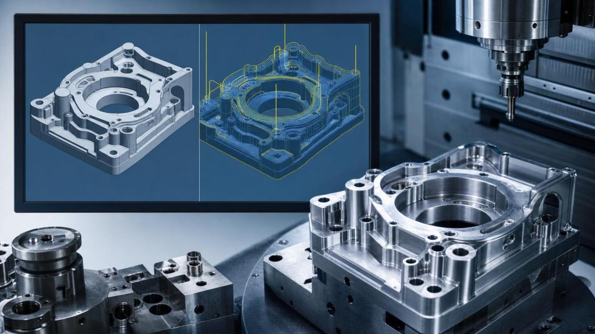
Most engineers assume conversion is complete if the part opens in the CAM system and toolpaths can be generated. In reality, cad to cam conversion data loss often occurs in 4 layers: geometry, attributes, relationships, and manufacturing intent. Each layer has different consequences for cost, lead time, and quality.
Geometry loss: visible, measurable, and sometimes subtle
Geometry is usually the most preserved element, especially when neutral formats such as STEP are used. However, even here, issues appear in imported solids, trimmed surfaces, spline continuity, and tiny edge gaps. A 0.01 mm mismatch can be irrelevant for roughing but unacceptable for high-speed finishing or 5-axis swarf cutting.
Typical failures include missing fillets, broken surfaces, misread hole axes, and tolerance stack shifts across imported assemblies. For components with ±0.02 mm feature tolerance, a minor translation defect can create a chain reaction: toolpath error, inspection failure, rework, and a 2–5 day schedule slip.
Metadata loss: the hidden project risk
Metadata is often where the most damaging cad to cam conversion data loss occurs. Material callouts, revision levels, surface finish notes, part numbers, datum references, layer naming, and machining allowances may not transfer cleanly between systems. The geometry survives, but the manufacturing context becomes incomplete.
This matters for project managers because metadata errors are harder to detect than broken faces. A CAM programmer may machine the right shape with the wrong stock allowance, omit a critical finish pass, or miss a setup note tied to a tolerance-critical face. These are not software inconveniences; they are execution risks.
Feature intelligence loss in native-to-neutral translation
When a native CAD model is exported into a neutral format, the receiving CAM platform frequently loses parametric history and feature recognition. A pocket becomes only surfaces. A tapped hole becomes only cylindrical geometry. A patterned feature becomes repeated bodies without design logic.
This can increase programming time by 15% to 40% on complex parts because programmers must manually re-identify machinable features. On a 60-part batch or a 3-stage prototype cycle, that overhead directly affects quoting accuracy and machine availability.
The table below shows common data categories affected during translation and the likely production impact for engineering teams.
The key insight is that not all lost data has equal cost. A missing cosmetic layer may be manageable, while a lost datum frame or incorrect hole depth can affect first-pass yield immediately. Project teams should rank conversion risks by manufacturing consequence, not by file complexity alone.
How Much Data Gets Lost in Practice?
There is no universal percentage because data loss depends on software pairings, file format, modeling discipline, and part complexity. In practice, direct native import between tightly integrated platforms may preserve 85% to 95% of usable manufacturing information, while neutral exchange for complex parts may preserve geometry well but retain far less feature and annotation intelligence.
For project planning, it is more useful to think in terms of risk bands rather than a single loss number. A simple 2.5-axis bracket may experience low-impact translation loss. A 5-axis aerospace housing with PMI-driven tolerancing, multiple setups, and surface finish zones may face moderate to high operational loss even if the model looks complete.
A practical risk model for project managers
A manageable approach is to classify cad to cam conversion data loss into 3 categories: low, moderate, and critical. Low means lost data does not change machining strategy. Moderate means manual reconstruction is required. Critical means the translated model can produce wrong machining decisions if unchecked.
Low-risk conversion
This usually applies to prismatic parts, limited annotation dependence, and stable solid geometry. Typical review time is 10–20 minutes per file. CAM output remains reliable if standard pre-flight checks are followed.
Moderate-risk conversion
This often includes imported assemblies, mixed surfaces, nonstandard hole logic, or partial PMI transfer. Manual verification may take 30–90 minutes. This category is common in supplier handoff environments where design and machining teams use different software stacks.
Critical-risk conversion
This includes high-value parts with ±0.01 mm to ±0.05 mm tolerances, freeform surfaces, 5-axis orientation control, or safety-related features. Review can exceed 2 hours per part, and the cost of one unnoticed translation error can outweigh the time saved by a rushed release.
- Simple parts: often low visible loss, but still check coordinate systems and hole definitions.
- Multi-setup parts: watch for origin shifts, stock orientation, and fixture reference breakdown.
- Regulated or aerospace parts: verify PMI, GD&T, datum structures, and revision traceability every time.
The most important planning lesson is that conversion quality should be estimated before CAM programming starts. If a high-risk file enters production without controlled review, the downstream cost may show up as delayed FAI, machine downtime, or supplier dispute rather than as an obvious digital error.
The Main Causes of CAD to CAM Conversion Data Loss
Data loss is rarely caused by one bad export alone. It usually comes from a chain of technical and process decisions across design, procurement, supplier communication, and manufacturing engineering. Understanding the causes helps project teams choose the right prevention controls.
1. File format mismatch
Native files can preserve more intelligence, but they also create software dependency. Neutral formats such as STEP, IGES, Parasolid, or DXF improve interoperability, yet they may strip parametric behavior or annotation meaning. IGES is still seen in legacy supply chains, but it often requires more geometry repair than modern STEP workflows.
2. Poor model hygiene
Unstitched surfaces, duplicate faces, inconsistent naming, and unfinished revision cleanup create translation issues before export even begins. In many cross-border sourcing projects, 20% of conversion problems are not software defects at all. They are model discipline problems originating upstream.
3. PMI dependence without validation
Model-based definition is growing, but if the receiving CAM environment does not interpret PMI consistently, critical information can vanish silently. This is especially risky when no 2D release package or tolerance validation checklist exists as backup.
4. Multi-supplier handoff complexity
In distributed manufacturing, a design team, contract programmer, and machining supplier may each use different platforms. Every handoff increases the chance of cad to cam conversion data loss. Even one extra translation step can introduce ambiguity in stock state, fixture assumptions, or tool access direction.
The following comparison helps procurement and engineering teams choose file strategies based on risk tolerance and production context.
For most B2B manufacturing programs, STEP plus a controlled drawing or PMI validation package offers the best balance between interoperability and risk control. The exact choice should reflect tolerance level, supplier maturity, and how much manufacturing intent is embedded in the model.
How to Reduce Data Loss Before It Reaches the Machine
Project managers do not need to eliminate every translation artifact. They need a repeatable process that catches high-consequence loss early. A strong control plan usually has 5 steps and can be embedded into supplier onboarding, release management, and first-article preparation.
Step 1: Define the master data source
Every project should identify whether the legal authority is the native model, translated model, 2D drawing, or controlled PMI package. Without that decision, teams debate interpretation after problems appear rather than before machining starts.
Step 2: Use a conversion checklist tied to part criticality
A simple bracket may need 6 checks. A turbine-adjacent, aerospace, or medical component may require 15 or more checks. At minimum, verify geometry integrity, units, coordinate system, hole data, stock allowance, and tolerance-bearing annotations.
Step 3: Validate in the receiving CAM environment
Do not rely on the export system’s preview. The translated file must be reviewed in the actual CAM environment used for programming. Many conversion issues appear only after tool orientation, surface selection, or automated feature recognition is attempted.
Step 4: Require supplier feedback before release lock
In outsourced machining, the fastest way to reduce cad to cam conversion data loss is to force questions early. A 24-hour supplier review window for critical parts can prevent a 2-week disruption later. Encourage suppliers to flag unclear datums, missing notes, or abnormal geometry immediately.
Step 5: Capture lessons into a standard workflow
If the same software pair or supplier route is used repeatedly, document known failure points. Over 3 to 5 production cycles, teams can reduce manual repair time, improve quote accuracy, and stabilize first-pass success rates.
- Set approved export formats by part family.
- Match review depth to tolerance criticality.
- Keep revision history visible across all transfers.
- Use pilot runs for new supplier-software combinations.
- Audit post-conversion files before NC release.
For organizations sourcing globally, this discipline is more than a technical best practice. It is a procurement control mechanism. Clean translation reduces ambiguity in RFQs, shortens supplier qualification cycles, and lowers the probability of disputes over whether a defect came from design, programming, or machining.
What Project Managers Should Ask Suppliers and Internal Teams
A strong project lead does not need to inspect every surface personally. The more effective approach is to ask precise questions that expose weak digital handoffs before they become physical defects. The questions below work well during sourcing, NPI planning, and production transfer reviews.
Questions for internal engineering teams
- Which file is the release authority: native, STEP, or 2D package?
- Are there any features with tolerance tighter than ±0.05 mm that require manual confirmation?
- Does the part depend on PMI, datum logic, or special finish notes not guaranteed in neutral exchange?
- Has the file been tested in the same CAM platform used by production?
Questions for suppliers or programming partners
- Which import method do you use, and what translation issues are common in your workflow?
- How long does geometry repair typically take for complex 3-axis versus 5-axis parts?
- What is your process if hole definitions, origins, or datum references do not import correctly?
- Can you provide a pre-machining review within 1 business day for critical components?
These questions help convert an abstract discussion about digital continuity into an executable supplier quality process. For engineering leaders, that means fewer surprises. For procurement teams, it creates clearer accountability during qualification and launch.
Turning Conversion Control Into a Competitive Advantage
The real cost of cad to cam conversion data loss is not the translation event itself. It is the downstream uncertainty it introduces into planning, quoting, machining, inspection, and delivery. When teams control that uncertainty, they improve schedule reliability and reduce the hidden cost of engineering trial and error.
For organizations operating in robotics, aerospace, sensors, edge devices, and precision machining, the lesson is consistent: a file that opens is not the same as a file that is production-safe. Conversion quality must be judged by whether engineering intent remains usable at the machine, at the inspection station, and across the supplier chain.
TechStat Vanguard focuses on this exact standard of engineering truth: stripping away assumptions and evaluating what survives in real manufacturing conditions. If your team is comparing suppliers, tightening release processes, or assessing digital manufacturing risk, now is the time to build a more rigorous conversion control framework.
To explore a more reliable path from design data to machining execution, contact us for a tailored benchmarking discussion, request a custom review framework, or learn more about practical hard-tech decision support for complex manufacturing programs.
Search News
Hot Articles
- Carbon Fiber StructuresHow to Specify Aerospace Carbon Fiber Assemblies for Lightweight, Load-Bearing PartsJul 11, 2026
- Machine VisionXiaomi, Alibaba DAMO Academy Drive Open-Source Robotics Model Ecosystem, Lowering Algorithm Development Barriers for Overseas SMEs Adopting Chinese Robotics SolutionsMar 30, 2026
- Cobots & ArmsShanxi 'AI+' Conference Showcases Embodied Intelligence with Multinational Buyer Engagement: Key Industry ImplicationsMar 30, 2026
Popular Tags
Recommended News
 Jul 11, 2026How to Specify Aerospace Carbon Fiber Assemblies for Lightweight, Load-Bearing PartsAerospace carbon fiber assemblies: learn how to specify laminate design, load data, joining methods, and inspection controls for lighter, reliable load-bearing aerospace parts.Elena Rostova (UAV Systems Researcher)
 Mar 30, 2026Xiaomi, Alibaba DAMO Academy Drive Open-Source Robotics Model Ecosystem, Lowering Algorithm Development Barriers for Overseas SMEs Adopting Chinese Robotics SolutionsXiaomi & Alibaba DAMO Academy's open-source robotics models lower algorithm barriers for global SMEs. Boost efficiency in manufacturing, logistics & smart retail with ROS 2 compatible solutions.TSV Data Lab
 Mar 30, 2026Shanxi 'AI+' Conference Showcases Embodied Intelligence with Multinational Buyer Engagement: Key Industry ImplicationsShanxi 'AI+' Conference highlights embodied intelligence with Tesla, Ubtech & Jiantao showcasing multimodal robotics. 40+ global buyers validated tech on-site, creating new B2B channels for industrial automation & AI solutions.Chen Wei (Automation Lead Engineer)
 Mar 30, 2026Zhongguancun Unveils 6G Integrated Sensing-Computing-Intelligence Platform to Empower Embodied Robots for Global Industrial ApplicationsZhongguancun's new 6G platform revolutionizes industrial robotics with <10ms latency, empowering global automotive, logistics & port automation. Discover how this tech boosts China's smart manufacturing exports.TSV Data Lab
 Mar 30, 2026Mech-Mind Tianjin Embodied Intelligence R&D and Production Base Goes Live, Cutting Delivery Time by 20%–30% for Global Customized AMR+Vision SolutionsMech-Mind's Tianjin AMR+Vision production base cuts delivery time by 20%-30% for欧美 & Latin American markets. Discover how this PLd-certified facility accelerates customized robotics solutions for smart manufacturing and logistics.Chen Wei (Automation Lead Engineer)
 Mar 30, 2026Boao Forum Reveals 'Co-evolution of Big and Small Brains' Trend in Humanoid Robots, China's Embodied Intelligence Accelerates Adaptation to Overseas Manufacturing Service ScenariosDiscover how China's humanoid robots, featuring 'Co-evolution of Big and Small Brains,' are revolutionizing global manufacturing. Learn about Embodied Tian Gong 3.0's ISO compliance and overseas deployment at Boao Forum 2026.Chen Wei (Automation Lead Engineer)
 Mar 30, 2026China Railway Industrial Secures Patent for Embodied Robotics in Material Handling, Boosting High-Precision Delivery Capabilities for Overseas Infrastructure and Manufacturing ProjectsChina Railway Industrial's new patent for embodied robotics in material handling boosts high-precision delivery for global infrastructure & manufacturing. Discover how this innovation enhances logistics accuracy in automotive, rail transit & EPC projects.Chen Wei (Automation Lead Engineer)
 Oct 10, 2026How to Select a Machine Performance Monitoring Platform for OEE and Downtime ReductionMachine performance monitoring platform selection guide: validate machine states, OEE data, downtime reasons, integrations, and scalability to reduce losses with confidence.TSV Data Lab
 Oct 08, 2026How to Machine Inconel 625 Blades Without Heat Cracks or Edge ChippingInconel 625 blade machining guide: prevent heat cracks, edge chipping, chatter, and work hardening with proven tooling, cooling, fixturing, and inspection strategies.Dr. Marcus Vance
 Oct 07, 2026How to Evaluate an HMI Panel Distributor for Industrial Automation ProjectsHMI panel distributor evaluation guide: verify technical compatibility, traceability, supply reliability, lifecycle support, and total cost for automation projects.Victor Lin (Chief Software Architect)
 Oct 06, 2026Navigation Fault Tolerance Standards for AMRs: What Safety Teams Must VerifyNavigation fault tolerance standards: learn what AMR safety teams must verify, from localization loss and sensor faults to stopping distance, safe restart, and site-specific validation.Chen Wei (Automation Lead Engineer)
 Oct 05, 2026Calculating Edge Computing Total Cost of Ownership Across Distributed SitesEdge computing ownership cost explained: calculate deployment, energy, connectivity, security, remote support, and refresh costs across distributed sites.TSV Data Lab
 Oct 04, 2026CAD/CAM Benchmarking in the GCC: What Manufacturers Should Ask a ConsultantCAD CAM benchmark consultant GCC guide: learn the key questions manufacturers should ask to validate post-processors, workflows, machine performance, and production risk.Victor Lin (Chief Software Architect)
 Oct 03, 2026Selecting Automotive Radar Sensor Modules for ADAS Range, Resolution, and IntegrationAutomotive radar sensor module selection guide for ADAS: compare range, resolution, field of view, latency, and integration to build safer, reliable vehicle systems.TSV Data Lab
 Oct 02, 2026How to Qualify Machined Parts Suppliers for Hard Tech ProgramsHard tech supply chain machined parts demand rigorous supplier qualification. Learn how to assess capability, traceability, quality controls, and delivery resilience.Dr. Marcus Vance
 Oct 01, 2026How to Select an Outdoor Security Radar Sensor for Perimeter Detection?Outdoor security radar sensor selection guide: compare range, accuracy, false-alarm control, integration, and field testing for reliable perimeter detection.TSV Data Lab
 Sep 30, 2026How to Evaluate Solid-State LiDAR Hardware for Outdoor Autonomous VehiclesSolid state LiDAR hardware evaluation guide for outdoor autonomous vehicles—compare range, point-cloud quality, environmental resilience, integration, and safety.TSV Data Lab
 Sep 29, 2026ISO 9283 Repeatability: How to Evaluate Cobot Positioning PerformanceISO 9283 cobot repeatability explained: learn how payload, reach, approach direction, and test conditions affect positioning performance and cell capability.Chen Wei (Automation Lead Engineer)
 Oct 10, 2026When does the cost of industrial robots pay back in high-volume production?Cost of industrial robots: discover how high-volume manufacturers calculate payback through uptime, cycle time, labor, quality, and integration before investing.Chen Wei (Automation Lead Engineer)
 Oct 09, 2026What does a manufacturing robot really cost beyond the purchase price?Manufacturing robot cost goes far beyond the purchase price. Explore integration, tooling, safety, uptime, and total ownership factors for smarter automation investments.Chen Wei (Automation Lead Engineer)
 Oct 08, 2026AGV vs. AMR: Which Is Better for Frequently Changing Routes?Which is better for changing routes? Compare AGVs and AMRs for flexible navigation, docking precision, traffic control, and faster facility reconfiguration.Chen Wei (Automation Lead Engineer)
 Oct 07, 2026How Much Does an Automated Guided Vehicle Cost in 2026?How much does an automated guided vehicle cost in 2026? Explore AGV price ranges, hidden deployment costs, and smart buying factors for stronger ROI.Chen Wei (Automation Lead Engineer)
 Oct 06, 2026Are Collaborative Robots Safe Enough to Operate Without Fencing?Are collaborative robots safe enough to work without fencing? Explore risk assessment, safeguarding options, and practical guidance for safer, productive cobot cells.Chen Wei (Automation Lead Engineer)
 Oct 05, 2026What Causes Machine Vision Systems to Miss Small Defects?What causes machine vision systems to miss small defects? Discover how lighting, optics, motion, and AI thresholds affect detection—and prevent costly escapes.TSV Data Lab