How Fatigue-Resistant Aerospace Carbon Fiber Components Are Specified and Tested
Publication Date
author
In aerospace structures, fatigue is rarely a dramatic single-event failure. It is usually a slow accumulation of micro-damage under repeated loading.
That is why fatigue resistant aerospace carbon fiber components are specified through measurable engineering criteria, not broad claims about strength or lightweight performance.
For platforms ranging from commercial aircraft interiors to UAV airframes and control surfaces, long-term reliability depends on laminate design, defect control, load assumptions, and disciplined test evidence.
In a market crowded with vague composite marketing, the real differentiator is traceable data. That principle sits at the center of TechStat Vanguard’s view of hard-tech evaluation.
Why fatigue performance has become a sharper specification issue
Composite adoption has expanded far beyond flagship airframes. It now reaches secondary structures, UAV fuselages, radomes, brackets, fairings, rotor elements, and mission-specific payload frames.
As component variety increases, so does the risk of comparing suppliers through incomplete data sets. A tensile strength number alone says very little about fatigue durability.
Repeated bending, vibration, thermal cycling, impact exposure, and assembly preload can all change how carbon fiber parts degrade over time.
This matters across the wider industrial chain as well. Edge sensing systems, robotics housings, and precision fixtures increasingly borrow aerospace composite practices where weight and cyclic stability both matter.
So the current question is not whether carbon fiber is strong. The question is whether a given component can sustain its expected load spectrum with acceptable damage growth and residual strength.
What engineers are really specifying
When fatigue resistant aerospace carbon fiber components are specified correctly, the document defines a performance envelope, not just a material family.
The starting point is usually the structural function. A wing skin panel, UAV boom, battery tray, or equipment mount will each fail through different mechanisms.
That leads to several linked specification layers.
Material system and laminate architecture
Fiber type, resin system, prepreg format, cure cycle, stacking sequence, and fiber volume fraction all affect fatigue behavior.
Unidirectional laminates may perform very differently from woven architectures under off-axis cyclic loads. Toughened resin systems may improve damage tolerance after impact.
Load spectrum and environment
A good specification states expected stress ratios, cycle counts, frequency limits, temperature range, humidity exposure, and likely out-of-plane events.
Without that context, fatigue data from one application can be misleading in another.
Acceptance criteria
Requirements may include stiffness retention, residual compression strength, delamination growth limits, strain thresholds, visible damage limits, and inspection intervals.
For critical structures, specification language often distinguishes between no-growth damage assumptions and slow-growth damage assumptions.
How fatigue resistant aerospace carbon fiber components are tested
Testing usually follows a building-block logic. That means data is gathered from simple coupons first, then elements, then subcomponents, then full structural articles where needed.
This progression is efficient because fatigue behavior is sensitive to both material quality and geometry-specific details such as holes, joints, ply drops, and bonded interfaces.
Coupon-level screening
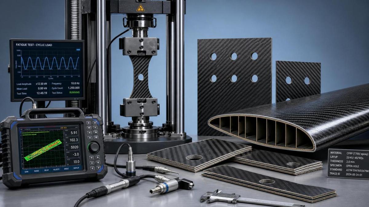
Basic fatigue tests often establish S-N behavior, compression-after-impact response, interlaminar properties, and environmental knockdown factors.
These tests help narrow material systems before expensive structural validation begins.
Feature and element testing
Open-hole specimens, bolted joints, bonded joints, corners, and stiffened panels reveal where local stress concentrations drive early damage.
For many fatigue resistant aerospace carbon fiber components, these details are more decisive than nominal laminate strength.
Subcomponent and full-scale validation
Representative assemblies are then tested under realistic cyclic loading, often with combined tension, compression, torsion, vibration, and thermal effects.
Instrumentation may include strain gauges, digital image correlation, acoustic emission, ultrasonic inspection, and stiffness-trend monitoring.
Standards matter, but traceability matters more
Composite fatigue programs are often linked to standards from ASTM, ISO, SACMA legacy methods, aerospace primes, and certification frameworks such as FAA or EASA expectations.
Still, citing a standard is not enough. Test traceability determines whether data can support a real sourcing or qualification decision.
Useful traceability usually includes batch identity, cure records, void content, layup route, operator control, fixture definition, conditioning history, instrumentation method, and failure documentation.
This is where many supplier comparisons break down. One report may show attractive cycle counts, but omit impact preconditioning or hide a non-representative stress ratio.
TSV’s data-first perspective is relevant here because the real commercial filter is not presentation quality. It is parameter completeness.
Failure modes that deserve closer attention
Not all fatigue damage in carbon fiber composites looks obvious at first inspection. Some of the most important degradation mechanisms begin below the visible surface.
- Matrix cracking that gradually reduces stiffness and redistributes stress.
- Delamination growth near free edges, fastener holes, or ply terminations.
- Fiber breakage after local overload events within a cyclic sequence.
- Bondline degradation in hybrid metal-composite or composite-composite joints.
- Impact-induced hidden damage that sharply reduces compression fatigue life.
These mechanisms explain why fatigue resistant aerospace carbon fiber components cannot be judged by static tensile data or resin datasheets alone.
Where the business risk actually sits
In practice, fatigue evaluation is tied to cost, qualification time, maintenance burden, and liability exposure.
A component that passes early bench tests but lacks robust fatigue characterization can create redesign loops later in certification, fleet service, or supplier transition.
That risk is especially visible in fast-moving sectors such as UAV systems, where production timelines are compressed and field loads can be less predictable.
It also affects adjacent industrial sectors using aerospace-derived composite strategies. When lightweight structures carry sensors, batteries, or motion assemblies, cyclic stability becomes a system issue.
A better evaluation framework shortens that uncertainty. It turns vague supplier claims into comparable engineering evidence.
A practical framework for comparing data packages
When reviewing fatigue resistant aerospace carbon fiber components, a compact checklist is often more useful than a long narrative brochure.
- Check whether the laminate and cure route match the intended production article.
- Confirm the load spectrum, stress ratio, and environmental conditions behind every fatigue result.
- Review knockdown factors for moisture, temperature, impact, and manufacturing defects.
- Look for element-level evidence on holes, joints, bonded interfaces, and ply drops.
- Verify residual strength criteria after cyclic exposure, not only cycles to first damage.
- Ask whether non-destructive inspection methods were used during and after testing.
- Trace every result to batch records, specimen geometry, acceptance rules, and failure images.
That level of discipline aligns with a broader hard-tech sourcing reality. Useful decisions come from comparable parameters, not polished language.
What to evaluate next
The next step is usually to translate mission needs into a sharper specification package.
That means defining service loads, inspection philosophy, acceptable damage states, qualification hierarchy, and the exact evidence required from suppliers or internal labs.
For fatigue resistant aerospace carbon fiber components, the strongest position comes from linking design intent, test method, and traceable manufacturing data into one decision trail.
Once that trail is clear, comparisons become faster, qualification cycles become shorter, and structural confidence rests on engineering truth rather than market noise.
Search News
Hot Articles
- Carbon Fiber StructuresHow to Specify Aerospace Carbon Fiber Assemblies for Lightweight, Load-Bearing PartsJul 11, 2026
- Machine VisionXiaomi, Alibaba DAMO Academy Drive Open-Source Robotics Model Ecosystem, Lowering Algorithm Development Barriers for Overseas SMEs Adopting Chinese Robotics SolutionsMar 30, 2026
- Cobots & ArmsShanxi 'AI+' Conference Showcases Embodied Intelligence with Multinational Buyer Engagement: Key Industry ImplicationsMar 30, 2026
Popular Tags
Recommended News
 Jul 11, 2026How to Specify Aerospace Carbon Fiber Assemblies for Lightweight, Load-Bearing PartsAerospace carbon fiber assemblies: learn how to specify laminate design, load data, joining methods, and inspection controls for lighter, reliable load-bearing aerospace parts.Elena Rostova (UAV Systems Researcher)
 Mar 30, 2026Xiaomi, Alibaba DAMO Academy Drive Open-Source Robotics Model Ecosystem, Lowering Algorithm Development Barriers for Overseas SMEs Adopting Chinese Robotics SolutionsXiaomi & Alibaba DAMO Academy's open-source robotics models lower algorithm barriers for global SMEs. Boost efficiency in manufacturing, logistics & smart retail with ROS 2 compatible solutions.TSV Data Lab
 Mar 30, 2026Shanxi 'AI+' Conference Showcases Embodied Intelligence with Multinational Buyer Engagement: Key Industry ImplicationsShanxi 'AI+' Conference highlights embodied intelligence with Tesla, Ubtech & Jiantao showcasing multimodal robotics. 40+ global buyers validated tech on-site, creating new B2B channels for industrial automation & AI solutions.Chen Wei (Automation Lead Engineer)
 Mar 30, 2026Zhongguancun Unveils 6G Integrated Sensing-Computing-Intelligence Platform to Empower Embodied Robots for Global Industrial ApplicationsZhongguancun's new 6G platform revolutionizes industrial robotics with <10ms latency, empowering global automotive, logistics & port automation. Discover how this tech boosts China's smart manufacturing exports.TSV Data Lab
 Mar 30, 2026Mech-Mind Tianjin Embodied Intelligence R&D and Production Base Goes Live, Cutting Delivery Time by 20%–30% for Global Customized AMR+Vision SolutionsMech-Mind's Tianjin AMR+Vision production base cuts delivery time by 20%-30% for欧美 & Latin American markets. Discover how this PLd-certified facility accelerates customized robotics solutions for smart manufacturing and logistics.Chen Wei (Automation Lead Engineer)
 Mar 30, 2026Boao Forum Reveals 'Co-evolution of Big and Small Brains' Trend in Humanoid Robots, China's Embodied Intelligence Accelerates Adaptation to Overseas Manufacturing Service ScenariosDiscover how China's humanoid robots, featuring 'Co-evolution of Big and Small Brains,' are revolutionizing global manufacturing. Learn about Embodied Tian Gong 3.0's ISO compliance and overseas deployment at Boao Forum 2026.Chen Wei (Automation Lead Engineer)
 Mar 30, 2026China Railway Industrial Secures Patent for Embodied Robotics in Material Handling, Boosting High-Precision Delivery Capabilities for Overseas Infrastructure and Manufacturing ProjectsChina Railway Industrial's new patent for embodied robotics in material handling boosts high-precision delivery for global infrastructure & manufacturing. Discover how this innovation enhances logistics accuracy in automotive, rail transit & EPC projects.Chen Wei (Automation Lead Engineer)
 Oct 12, 2026How to Verify RoHS Compliance in Industrial Sensing Systems Before DeploymentRoHS compliant sensing systems: learn how to verify materials, supplier declarations, testing, and configuration controls before industrial deployment.TSV Data Lab
 Oct 11, 2026How Procurement-Oriented Content Taxonomy Improves B2B Buying JourneysProcurement-oriented content taxonomy streamlines B2B buying journeys with clearer evidence, supplier comparisons, risk visibility, and faster approvals.TSV Data Lab
 Oct 10, 2026How to Select a Machine Performance Monitoring Platform for OEE and Downtime ReductionMachine performance monitoring platform selection guide: validate machine states, OEE data, downtime reasons, integrations, and scalability to reduce losses with confidence.TSV Data Lab
 Oct 08, 2026How to Machine Inconel 625 Blades Without Heat Cracks or Edge ChippingInconel 625 blade machining guide: prevent heat cracks, edge chipping, chatter, and work hardening with proven tooling, cooling, fixturing, and inspection strategies.Dr. Marcus Vance
 Oct 07, 2026How to Evaluate an HMI Panel Distributor for Industrial Automation ProjectsHMI panel distributor evaluation guide: verify technical compatibility, traceability, supply reliability, lifecycle support, and total cost for automation projects.Victor Lin (Chief Software Architect)
 Oct 06, 2026Navigation Fault Tolerance Standards for AMRs: What Safety Teams Must VerifyNavigation fault tolerance standards: learn what AMR safety teams must verify, from localization loss and sensor faults to stopping distance, safe restart, and site-specific validation.Chen Wei (Automation Lead Engineer)
 Oct 05, 2026Calculating Edge Computing Total Cost of Ownership Across Distributed SitesEdge computing ownership cost explained: calculate deployment, energy, connectivity, security, remote support, and refresh costs across distributed sites.TSV Data Lab
 Oct 04, 2026CAD/CAM Benchmarking in the GCC: What Manufacturers Should Ask a ConsultantCAD CAM benchmark consultant GCC guide: learn the key questions manufacturers should ask to validate post-processors, workflows, machine performance, and production risk.Victor Lin (Chief Software Architect)
 Oct 03, 2026Selecting Automotive Radar Sensor Modules for ADAS Range, Resolution, and IntegrationAutomotive radar sensor module selection guide for ADAS: compare range, resolution, field of view, latency, and integration to build safer, reliable vehicle systems.TSV Data Lab
 Oct 02, 2026How to Qualify Machined Parts Suppliers for Hard Tech ProgramsHard tech supply chain machined parts demand rigorous supplier qualification. Learn how to assess capability, traceability, quality controls, and delivery resilience.Dr. Marcus Vance
 Oct 01, 2026How to Select an Outdoor Security Radar Sensor for Perimeter Detection?Outdoor security radar sensor selection guide: compare range, accuracy, false-alarm control, integration, and field testing for reliable perimeter detection.TSV Data Lab
 Sep 30, 2026How to Evaluate Solid-State LiDAR Hardware for Outdoor Autonomous VehiclesSolid state LiDAR hardware evaluation guide for outdoor autonomous vehicles—compare range, point-cloud quality, environmental resilience, integration, and safety.TSV Data Lab
 Sep 29, 2026ISO 9283 Repeatability: How to Evaluate Cobot Positioning PerformanceISO 9283 cobot repeatability explained: learn how payload, reach, approach direction, and test conditions affect positioning performance and cell capability.Chen Wei (Automation Lead Engineer)
 Oct 12, 2026What should be included in predictive maintenance pricing for factories?Predictive maintenance pricing for factories: compare sensors, software, integration, support, and total cost to secure measurable uptime gains and avoid hidden expenses.TSV Data Lab
 Oct 11, 2026How payload and reach change the cost of an industrial robotCost of industrial robot systems depends heavily on payload and reach. Learn how sizing, torque, tooling, safety, and lifecycle factors shape smarter automation investments.Chen Wei (Automation Lead Engineer)
 Oct 10, 2026When does the cost of industrial robots pay back in high-volume production?Cost of industrial robots: discover how high-volume manufacturers calculate payback through uptime, cycle time, labor, quality, and integration before investing.Chen Wei (Automation Lead Engineer)
 Oct 09, 2026What does a manufacturing robot really cost beyond the purchase price?Manufacturing robot cost goes far beyond the purchase price. Explore integration, tooling, safety, uptime, and total ownership factors for smarter automation investments.Chen Wei (Automation Lead Engineer)