Aerospace Materials in the UK: Choosing Metals and Composites for Aircraft
Publication Date
author
When an aircraft component must lose weight without compromising fatigue life or certification evidence, the lightest material on a datasheet is not automatically the right choice. Aluminium is often a practical starting point for established airframe structures; titanium suits demanding joints and elevated-temperature locations; nickel alloys serve hotter engine environments; and carbon-fibre composites can deliver high directional stiffness at low weight when their lay-up, damage tolerance and production process are controlled.
For teams assessing aerospace materials in the UK, the decision should begin with the component’s loads, temperature, environment and approval basis—not with a generic strength-to-weight ranking. A substitution that looks attractive as raw stock can become less compelling after machining, inspection, joining, scrap and in-service repair are included.
Start with the component, not the material family
Define the load path and failure modes before comparing grades. A skin panel, a highly loaded lug and an engine-adjacent bracket may all be described as structural parts, yet require very different evidence. Record the relevant tension, compression, shear, bearing and fatigue loads; the expected load spectrum; minimum and maximum service temperatures; exposure to moisture, fluids and corrosion; and the consequences of damage.
Then distinguish the properties that govern the design. A stiffness-limited panel may need more thickness even when a stronger alloy is selected. A lug may be controlled by bearing, fatigue or crack growth rather than tensile strength. For a composite panel, compression after impact and open-hole behaviour can be more relevant than the tensile strength quoted for the fibre.
Use properties for the exact material form and condition wherever possible: plate, extrusion, forging, casting, additively manufactured stock or laminate. Direction, thickness, heat treatment and manufacturing route can all change the values that are usable in a design calculation.
Where each option tends to fit
These are starting points, not interchangeable material specifications. In particular, a composite’s quoted fibre properties do not represent the properties of the finished laminate. Resin system, fibre architecture, ply orientation, cure cycle and defects all influence the part that will be inspected and approved.
Aluminium: an established baseline with condition-specific limits
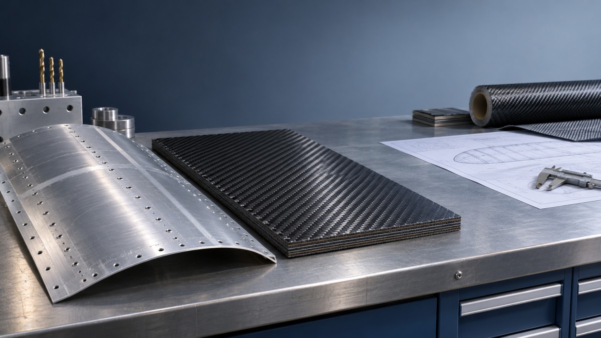
Aluminium remains a useful benchmark for airframe comparisons because it can be supplied in several product forms and has extensive service history in aerospace applications. It can be machined, formed or joined using established routes, although the viable process depends on alloy and temper. That combination makes it especially useful when the design must balance mass, production rate and maintainability.
The trade-off is that fatigue and corrosion performance cannot be inferred from static strength alone. Evaluate the specified alloy, temper and thickness against the expected spectrum, including holes, edges and surface finish. Corrosion protection and inspection access should be part of the design rather than additions made after the material is chosen. Where service temperature is significant, verify properties at temperature and after the relevant exposure.
Titanium and nickel alloys: different answers to demanding environments
Titanium is attractive for highly loaded fittings, interfaces and other locations where its strength, density and corrosion resistance justify the processing burden. Its low thermal conductivity can complicate machining, and tool selection, heat generation and surface integrity deserve attention. Assess the actual part geometry and supplier’s process capability; a material saving on a finished component can be offset by difficult machining from a large billet.
Nickel-based alloys are candidates for hotter engine and exhaust environments where temperature capability governs selection. Their density makes them less attractive for weight-sensitive structures without that thermal requirement. Creep, oxidation, thermal fatigue and exposure time may matter more than room-temperature tensile figures. The acceptable alloy, form and heat treatment must follow the applicable design and engine requirements.
Carbon-fibre composites: design the laminate as well as the part
A composite can place fibres along the principal load paths, but that benefit is directional. A laminate optimised for one load case may perform poorly under an unexpected transverse load, through-thickness stress or local bearing load. Compare complete laminate designs, including ply sequence, thickness, resin, manufacturing method and joint details, rather than comparing nominal fibre strength with metal yield strength.
Impact damage may be difficult to see while still reducing residual strength. Establish the assumed damage size, inspection method and interval, and the required residual strength for the intended structure. Moisture and temperature conditioning also matter: use properties appropriate to the service environment, not only dry room-temperature coupon results.
Compare designs on the same basis
A useful comparison is made between feasible component designs, not equal-sized blocks of material. Apply the same loads, geometry envelope, inspection assumptions and acceptance criteria to each candidate. Allow each design enough freedom to meet its own minimum thickness, joint and manufacturing constraints; a direct density substitution ignores these differences.
- Screen against non-negotiable limits. Remove candidates that cannot meet the temperature, chemical exposure, fire-related or structural requirements applicable to the part.
- Size for governing failure modes. Check stiffness, static strength, stability, fatigue and damage tolerance as relevant. Include holes, cut-outs, joints and local load introduction.
- Account for production. Compare material utilisation, forming or machining steps, cure tooling where applicable, non-destructive testing and likely rework routes.
- Assess service consequences. Include protective finishes, inspection access, repair provisions and the effect of damage or corrosion on continued operation.
- Check the evidence gap. Identify which properties and process records already exist for the proposed form and which require qualification or further testing.
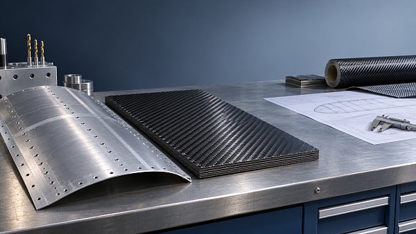
For example, replacing a machined aluminium bracket with composite is not simply a question of matching its tensile strength. The evaluation also needs a credible laminate, load introduction, fastener bearing performance, environmental protection and an inspection method. A titanium redesign may preserve a metallic load path but introduce a different machining and supply burden. Either option may be appropriate; neither can be judged from density alone.
Fatigue, joints and mixed-material interfaces
Aircraft structures experience repeated loading, so the assessment should reflect the intended spectrum rather than a single maximum load. For metals, consider crack initiation at holes and surface features, crack-growth behaviour, residual stress and inspection thresholds. Where the design relies on damage-tolerance principles, demonstrate that a detectable flaw can be found within the relevant inspection programme before it reaches a critical condition.
Composites need a different set of questions: can the structure tolerate barely visible impact damage, delamination or manufacturing defects? Are the coupon and element tests representative of the laminate, environment and loading? Compression, bearing and open-hole performance may control areas that appear generous in a fibre-direction tensile calculation.
At metal-to-composite interfaces, joining can determine the selection. Carbon fibre in electrical contact with a susceptible metal can contribute to galvanic corrosion when an electrolyte is present. Isolation layers, sealants, fastener choices and drainage may be needed, subject to the approved design. Also evaluate differential thermal expansion, local clamp-up, hole quality and access for inspection. A lighter panel is of limited value if the surrounding joint becomes heavier or harder to maintain.
Turn material data into a usable specification
A supplier quotation based only on an alloy name or “carbon fibre” leaves too much open. Define the material specification and revision, product form, dimensions, condition or temper, and any required processing. For composite material, identify the fibre and resin system, format, storage and handling requirements, cure or consolidation process, and laminate definition where applicable.
The evidence package should make it possible to connect the delivered material to its manufacturing and inspection history. Depending on the component and purchase requirements, request:
- Material certification identifying the specification, grade, form, condition and relevant batch or heat traceability.
- Test results and acceptance criteria applicable to the ordered product, including property direction and test condition where relevant.
- Records of specified heat treatment, cure, special processes and non-destructive inspection, with any deviations identified.
- Limits and disposition arrangements for defects, repairs, substitutions and changes to the manufacturing route.
Check that the reported results meet the purchase specification; a certificate is not a substitute for reviewing the actual requirements. Published handbook values or supplier datasheets can support screening, but design allowables must be appropriate to the approval basis, material population, processing and intended application. Establish who owns the evidence gap before committing to a material change.
UK sourcing and approval: verify the route for the actual part
For UK supply, ask where material is melted or produced, where it is converted into the ordered form, and where subsequent processing and inspection take place. A UK stockholder may supply material made elsewhere; location alone does not establish suitability or traceability. Confirm availability in the required dimensions and condition, particularly when the design depends on a specific plate thickness, forging route or composite system.
Quality-system certification can support supplier screening, but it does not by itself approve a material, process or aircraft part. Confirm the applicable customer requirements, approved supplier or processor status where required, scope of approval, and whether subcontracted heat treatment, coating or inspection is controlled. The relevant UK Civil Aviation Authority requirements and any other authority or customer requirements depend on the aircraft, organisation and approval route; establish those obligations at the start of the evaluation.
Before replacing an existing material, document the proposed change in full: specification and form, process route, design impacts, substantiation, inspection changes and effect on existing approvals. A nominally equivalent grade or a new source may still require assessment and approval under the governing design and quality processes. Treat the material decision as complete only when the required evidence can be produced for the part as manufactured and maintained.
Search News
Hot Articles
- Carbon Fiber StructuresHow to Specify Aerospace Carbon Fiber Assemblies for Lightweight, Load-Bearing PartsJul 11, 2026
- Machine VisionXiaomi, Alibaba DAMO Academy Drive Open-Source Robotics Model Ecosystem, Lowering Algorithm Development Barriers for Overseas SMEs Adopting Chinese Robotics SolutionsMar 30, 2026
- Cobots & ArmsShanxi 'AI+' Conference Showcases Embodied Intelligence with Multinational Buyer Engagement: Key Industry ImplicationsMar 30, 2026
Popular Tags
Recommended News
 Jul 11, 2026How to Specify Aerospace Carbon Fiber Assemblies for Lightweight, Load-Bearing PartsAerospace carbon fiber assemblies: learn how to specify laminate design, load data, joining methods, and inspection controls for lighter, reliable load-bearing aerospace parts.Elena Rostova (UAV Systems Researcher)
 Mar 30, 2026Xiaomi, Alibaba DAMO Academy Drive Open-Source Robotics Model Ecosystem, Lowering Algorithm Development Barriers for Overseas SMEs Adopting Chinese Robotics SolutionsXiaomi & Alibaba DAMO Academy's open-source robotics models lower algorithm barriers for global SMEs. Boost efficiency in manufacturing, logistics & smart retail with ROS 2 compatible solutions.TSV Data Lab
 Mar 30, 2026Shanxi 'AI+' Conference Showcases Embodied Intelligence with Multinational Buyer Engagement: Key Industry ImplicationsShanxi 'AI+' Conference highlights embodied intelligence with Tesla, Ubtech & Jiantao showcasing multimodal robotics. 40+ global buyers validated tech on-site, creating new B2B channels for industrial automation & AI solutions.Chen Wei (Automation Lead Engineer)
 Mar 30, 2026Zhongguancun Unveils 6G Integrated Sensing-Computing-Intelligence Platform to Empower Embodied Robots for Global Industrial ApplicationsZhongguancun's new 6G platform revolutionizes industrial robotics with <10ms latency, empowering global automotive, logistics & port automation. Discover how this tech boosts China's smart manufacturing exports.TSV Data Lab
 Mar 30, 2026Mech-Mind Tianjin Embodied Intelligence R&D and Production Base Goes Live, Cutting Delivery Time by 20%–30% for Global Customized AMR+Vision SolutionsMech-Mind's Tianjin AMR+Vision production base cuts delivery time by 20%-30% for欧美 & Latin American markets. Discover how this PLd-certified facility accelerates customized robotics solutions for smart manufacturing and logistics.Chen Wei (Automation Lead Engineer)
 Mar 30, 2026Boao Forum Reveals 'Co-evolution of Big and Small Brains' Trend in Humanoid Robots, China's Embodied Intelligence Accelerates Adaptation to Overseas Manufacturing Service ScenariosDiscover how China's humanoid robots, featuring 'Co-evolution of Big and Small Brains,' are revolutionizing global manufacturing. Learn about Embodied Tian Gong 3.0's ISO compliance and overseas deployment at Boao Forum 2026.Chen Wei (Automation Lead Engineer)
 Mar 30, 2026China Railway Industrial Secures Patent for Embodied Robotics in Material Handling, Boosting High-Precision Delivery Capabilities for Overseas Infrastructure and Manufacturing ProjectsChina Railway Industrial's new patent for embodied robotics in material handling boosts high-precision delivery for global infrastructure & manufacturing. Discover how this innovation enhances logistics accuracy in automotive, rail transit & EPC projects.Chen Wei (Automation Lead Engineer)
 Nov 19, 2026Choosing a Palletizing System for Bagged Food: Speed and Bag HandlingChoose the right palletizing system for bagged food. Compare throughput, bag handling, food safety, and robotic vs. conventional options.Chen Wei (Automation Lead Engineer)
 Nov 18, 2026Formnext 2026 Opens as Additive Manufacturing Advances Industrial ApplicationsFormnext 2026 highlights additive manufacturing innovations for industrial applications. Explore what they could mean for production, procurement and suppliers.Dr. Marcus Vance
 Nov 18, 2026Flexible Robotics Integration for High-Mix, Low-Volume ProductionFlexible robotics integration can make high-mix, low-volume production more adaptable. Explore practical ways to reduce changeover risk and plan a reliable robotic cell.Victor Lin (Chief Software Architect)
 Nov 17, 2026Formnext 2026: UK Additive Manufacturing Leads in Research but Faces Production BarriersUK additive manufacturing leads in research but faces barriers to production at scale. Explore the Formnext 2026 insights and what businesses should consider.Dr. Marcus Vance
 Nov 17, 2026Choosing Warehouse Automation Packaging Systems: Throughput and SpaceCompare warehouse automation packaging systems by throughput, footprint, and order mix. Discover how to choose a layout that meets peak demand.Victor Lin (Chief Software Architect)
 Nov 16, 2026China's October Industrial Robot Output Up 26%, 3D Printing Equipment Up 85.9%China's industrial robot output reportedly rose 26% in October, while 3D printing equipment grew 85.9%. Explore what the figures could mean for buyers.Chen Wei (Automation Lead Engineer)
 Nov 16, 2026Commercial Drones in North America: Choosing Payloads for Inspection and MappingCommercial drones North America: compare RGB, thermal and LiDAR payloads for inspection and mapping, and choose a system that delivers reliable data.Elena Rostova (UAV Systems Researcher)
 Nov 15, 2026Aerospace Materials in the UK: Choosing Metals and Composites for AircraftExplore aerospace materials UK teams use for aircraft. Compare metals and composites by weight, fatigue, manufacturing and approval needs to make informed choices.Dr. Marcus Vance
 Nov 14, 2026Ukraine Tests 3D-Printed Protective Structure Against M2 Heavy Machine-Gun FireUkraine’s 3D-printed protective structure reportedly resisted M2 heavy machine-gun fire. Explore the test’s limits and potential procurement implications.Dr. Marcus Vance
 Nov 14, 2026Rugged UAV Metrics: Assessing Wind Resistance, Endurance and IP RatingsCompare rugged UAV metrics for wind resistance, endurance and IP ratings. Learn what evidence to request and choose a platform fit for your mission.Chen Wei (Automation Lead Engineer)
 Nov 13, 2026Physical AI Gains Attention as Robot Investment Moves Beyond HardwarePhysical AI is reshaping robot investment beyond hardware. Explore what the shift toward perception and algorithms could mean for buyers and suppliers.Chen Wei (Automation Lead Engineer)
 Nov 13, 2026Precision Machining Benchmarks: A Guide to Tolerances and Surface FinishExplore this precision machining benchmarks guide to compare tolerances, surface finish, and inspection methods—and specify parts with confidence.Dr. Marcus Vance
 Nov 12, 2026Beijing Issues Three-Year Plan for Embodied AI Robotics IndustryBeijing’s embodied AI robotics plan targets leading humanoid robot makers by 2028. Explore its goals for supply chains, AI models and deployment.Chen Wei (Automation Lead Engineer)
 Nov 12, 2026Choosing an Edge AI Box for Robotics: Compute, Latency and I/OChoose the right edge AI box for robotics with practical guidance on compute, latency, sensor I/O and sustained performance. Explore the selection checklist.Chen Wei (Automation Lead Engineer)
 Nov 11, 2026Beijing Sets 200,000-Unit Annual Capacity Goal in Robotics PlanBeijing's robotics plan targets 200,000 units of annual capacity by 2027. Explore its technology goals, benchmark applications and adoption outlook.Chen Wei (Automation Lead Engineer)
 Nov 11, 2026Aero Engine Blade Machining: 5-Axis CNC Methods and ChallengesExplore aero engine blade machining, from 5-axis toolpaths to thin-wall challenges, surface integrity, and inspection. Learn what makes a process reliable.Dr. Marcus Vance
 Nov 10, 2026FAA Authorizes Skyways’ Long-Distance BVLOS Flights for Shell in Gulf of MexicoFAA authorizes Skyways’ long-distance BVLOS drone flights for Shell in the Gulf of Mexico. Discover what the decision means for offshore pipeline inspection.Elena Rostova (UAV Systems Researcher)