Commercial Drones in North America: Choosing Payloads for Inspection and Mapping
Publication Date
author
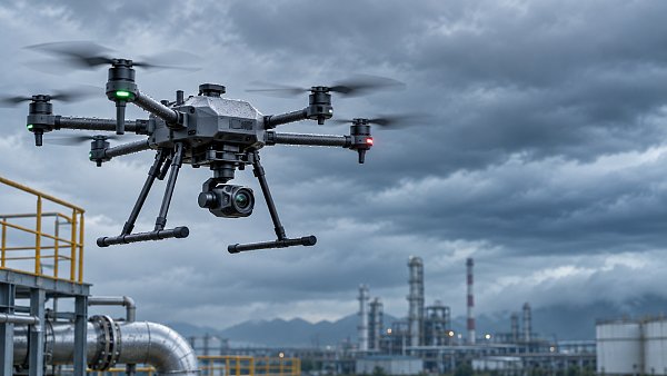
Choosing a drone payload begins with the decision the data must support, not the sensor with the longest specification sheet. A high-resolution RGB camera can document visible defects and produce detailed maps, but it cannot directly measure surface temperature or see the ground through vegetation. Thermal imaging and LiDAR solve different problems, and each introduces its own requirements for calibration, flight planning, data processing, and verification.
For commercial drones in North America, the practical choice is a system that can collect defensible data under the intended flight conditions while remaining compatible with the aircraft, processing workflow, and operating rules. Payload mass, power draw, field of view, positioning accuracy, and environmental constraints all influence the result.
Define the required observation before comparing sensors
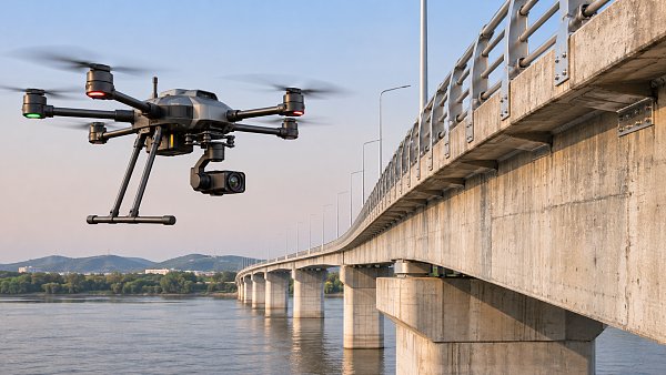
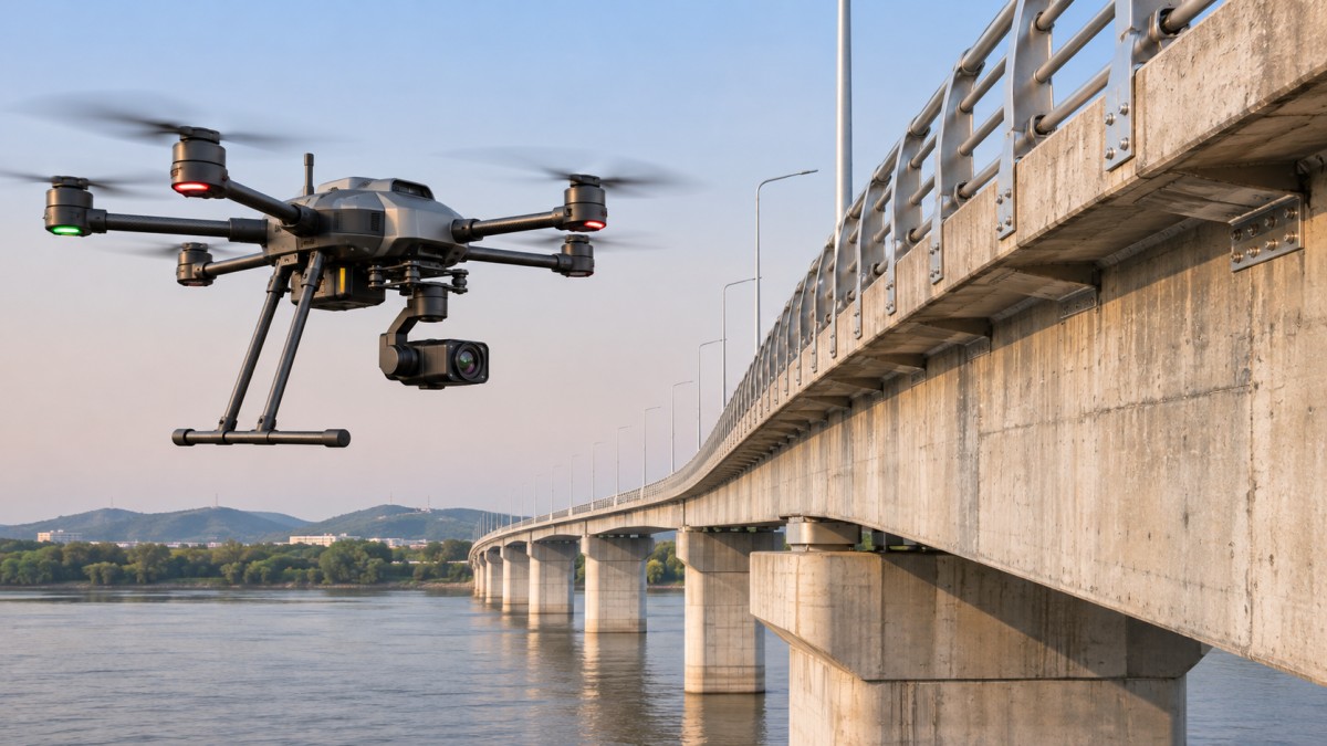
Inspection and mapping missions can use the same aircraft but demand different evidence. A bridge inspection may require images sharp enough to identify a specific surface defect from a safe standoff distance. A construction survey may require a georeferenced surface model whose elevation error remains within a defined tolerance. Neither requirement can be established from megapixels alone.
Translate the mission into measurable acceptance criteria: the smallest feature to be detected, the area to be covered, the required coordinate reference system, and the allowable horizontal and vertical error. Specify whether the deliverable is a set of photographs, an orthomosaic, a point cloud, a thermal anomaly report, or a combination. For inspections, distinguish between detecting an indication and measuring its dimensions; the latter requires stronger control over viewing geometry, image scale, and validation.
Operating geometry matters as much as sensor type. A camera pointed straight down is useful for mapping open terrain but may miss the underside of a structure. A side-facing or upward-looking inspection requires a suitable gimbal, adequate clearance, and a flight plan that accounts for obstructions. In some locations, the limiting component is not the sensor but the aircraft’s ability to place it safely where the target is visible.
RGB cameras: assess detail at the working distance
RGB imaging is a strong starting point for visible-condition surveys, progress documentation, orthomosaics, and photogrammetric models. Its value depends on the detail captured on the subject, not simply the number of pixels on the sensor. Ground sample distance (GSD) links pixel size, focal length, and distance to the target: at a given camera configuration, flying farther away increases the area represented by each pixel.
As an illustrative calculation, if a camera has a 2.4 µm pixel pitch and a 24 mm focal length, an object 50 m away corresponds to a nominal GSD of approximately 5 mm per pixel. That does not mean every 5 mm defect can be identified. Focus, motion blur, compression, lighting, lens quality, viewing angle, and contrast can make a feature difficult to distinguish even when its nominal size exceeds one pixel.
For a mapping camera, examine the actual lens and shutter configuration as well as image resolution. Rolling-shutter distortion can affect moving-platform imagery unless the workflow accounts for it. Interval shooting rate must support the desired image overlap at the planned aircraft speed. A camera that produces sharp photographs individually can still create a poor model if coverage is incomplete, image timing is unreliable, or surfaces lack enough visual texture for matching.
For close inspection, a zoom lens may preserve detail from a safer distance, but magnification also narrows the field of view and makes vibration and pointing errors more consequential. Check whether the stated focal length is optical or achieved by cropping, and whether the gimbal remains stable at the intended magnification. Oblique imagery can reveal vertical faces and structural details that a nadir-only survey misses, although it adds capture and processing demands.
Thermal payloads: temperature measurement is not just image resolution
A thermal camera can reveal temperature patterns that are invisible in RGB imagery, making it relevant to electrical, mechanical, building-envelope, and asset inspections. The key distinction is whether the mission requires an image showing relative hot and cold areas or radiometric data that supports temperature analysis. A visually clear thermal image is not, by itself, a validated temperature measurement.
Specify thermal detector resolution, lens field of view, sensitivity, and whether per-pixel radiometric data can be exported. Evaluate the size of the target in thermal pixels at the working distance. A small component may occupy too little of the image for a reliable reading even when its location is obvious in a high-resolution RGB view. Digital zoom does not create additional thermal detector detail.
Measured apparent temperature is affected by surface emissivity, reflected radiation, viewing angle, atmospheric conditions, and the proportion of the pixel occupied by the target. Shiny metal can reflect nearby heat sources or the sky, producing a misleading pattern. Wind, solar heating, operating load, and time since shutdown can also change the thermal signature. An electrical inspection requirement should therefore define asset loading and environmental conditions, not merely request a thermal camera.
Dual RGB and thermal payloads help place anomalies in context, but the two images may have different resolutions, fields of view, and optical centers. Confirm how the system aligns them and whether the raw thermal data remains accessible. Where a temperature threshold triggers maintenance, define how suspect readings will be checked using an appropriate contact or ground-based measurement method.
LiDAR or photogrammetry for mapping?
Photogrammetry estimates three-dimensional geometry from overlapping images. It is attractive where surfaces are visible, have sufficient texture, and can be photographed from multiple suitable angles. RGB imagery also provides color and visual context, which can make inspection and interpretation easier.
LiDAR measures ranges using laser returns and can provide useful geometry in conditions where image matching is difficult. For vegetated sites, some pulses may reach the ground through gaps in the canopy, potentially improving terrain modeling compared with an image-derived surface. It does not see through solid leaves or guarantee ground returns beneath dense vegetation. The usable result depends on canopy structure, scan pattern, flying height, incidence angle, and return processing.
Point density should be assessed on the surface that matters, not only as an aggregate figure in a brochure. A dense canopy point cloud may contain relatively few classified ground points. Similarly, a high nominal pulse rate does not ensure uniform coverage on vertical structures or at the edge of a swath. Ask for the expected point distribution and ground-return performance for the planned altitude, speed, and site conditions.
LiDAR also relies on accurate trajectory and sensor alignment. GNSS positioning, inertial measurement, timing, and boresight calibration all influence where points appear in the final coordinate system. A sharp-looking point cloud can still be systematically displaced or show mismatches between flight lines. Compare overlapping strips and independent control measurements rather than judging quality from visual density alone.
Separate image detail from geospatial accuracy
A small GSD describes image sampling; it does not establish the accuracy of an orthomosaic or elevation model. Geospatial error can arise from camera calibration, image geometry, GNSS errors, timing offsets, reconstruction, and the distribution of control points. Horizontal and vertical accuracy should be specified separately, against a stated datum and coordinate system.
RTK or PPK positioning can improve the estimated camera or sensor trajectory, but neither eliminates the need to validate the final deliverable. Ground control points constrain or improve a solution when used in processing; independent checkpoints assess the result and should not also be used as control in that same adjustment. Define how checkpoints will be distributed, surveyed, and compared with the output, including the error statistic and confidence convention used for acceptance.
Vertical references deserve particular attention when comparing data from different sources. Ellipsoidal heights and orthometric elevations are not interchangeable without an appropriate transformation or geoid model. A dataset can be internally consistent yet unsuitable for integration with existing engineering drawings if the reference systems or transformation parameters differ.
For repeat inspections, also specify repeatability: the ability to revisit comparable viewpoints and align datasets over time. A model that meets a one-time positional tolerance may still be difficult to use for change detection if coverage, lighting, sensor settings, or reference points vary substantially between flights.
Check the whole aircraft–payload system
Payload capacity is more than the mass of the sensor head. Include the gimbal, mounting hardware, cables, storage, positioning components, and any additional onboard computer. Verify the aircraft’s maximum takeoff mass and approved payload configuration, as well as center-of-gravity limits. A payload that fits mechanically may still create balance, vibration, or clearance problems.
Power requirements affect endurance and integration. Confirm supply voltage, peak and continuous draw, connector pinout, startup behavior, and the effect of payload operation on available flight time. Compare endurance estimates using the intended payload, battery condition, wind allowance, operating temperature, and reserve policy—not an unloaded aircraft figure.
Data interfaces can become the limiting factor after the flight. Check whether image triggering is synchronized with positioning timestamps, whether LiDAR data can be paired with the trajectory, and whether onboard storage sustains the required recording rate. Review export formats, metadata, calibration files, software licensing, and the ability to process data in the intended workflow. A payload that generates usable data only through an incompatible or unavailable processing environment can undermine the specification even if its sensor performance is adequate.
For cold-weather missions, verify operating and storage temperature ranges for both the payload and batteries. Condensation, snow cover, low sun angles, and wind can affect measurements or flight availability. These are mission conditions to include in acceptance testing, not assumptions that every system marketed for outdoor use will tolerate equally.
Operational constraints belong in the specification
Aircraft and payload selection must fit the jurisdiction and the proposed operation. In the United States, many civil small-drone operations fall under FAA Part 107, with requirements and potential waivers depending on the operation. Canada applies its own Transport Canada rules for remotely piloted aircraft systems. Airspace authorization, operations near people, visual line of sight, and other conditions can affect whether the planned flight profile is permissible.
Do not assume that a payload’s advertised range or autonomous capability authorizes flight beyond visual line of sight, or that an approval in one country applies in another. Site permissions, critical-infrastructure restrictions, privacy obligations, radio equipment requirements, and customer data-handling terms may also affect deployment. Check the applicable rules and approvals for the exact location, aircraft, and mission before finalizing the operating concept.
Use a representative acceptance test
The most useful comparison is a controlled trial against the intended deliverable. Set a representative target distance, flight speed, lighting condition, and surface type. Include the smallest feature that must be detected or independently surveyed checkpoints for a mapping task. For LiDAR, examine ground returns and alignment between overlapping flight lines; for thermal work, include a suitable reference and record environmental and equipment conditions.
Require the supplier to provide both processed outputs and the supporting data needed to assess them: original imagery or sensor data where available, calibration information, trajectory quality, processing settings, and a report of omissions or rejected areas. Compare coverage, accuracy, and processing effort alongside flight duration. A system should be accepted because it produces the specified evidence reliably under defined conditions—not because a single headline parameter looks superior.
Search News
Hot Articles
- Carbon Fiber StructuresHow to Specify Aerospace Carbon Fiber Assemblies for Lightweight, Load-Bearing PartsJul 11, 2026
- Machine VisionXiaomi, Alibaba DAMO Academy Drive Open-Source Robotics Model Ecosystem, Lowering Algorithm Development Barriers for Overseas SMEs Adopting Chinese Robotics SolutionsMar 30, 2026
- Cobots & ArmsShanxi 'AI+' Conference Showcases Embodied Intelligence with Multinational Buyer Engagement: Key Industry ImplicationsMar 30, 2026
Popular Tags
Recommended News
 Jul 11, 2026How to Specify Aerospace Carbon Fiber Assemblies for Lightweight, Load-Bearing PartsAerospace carbon fiber assemblies: learn how to specify laminate design, load data, joining methods, and inspection controls for lighter, reliable load-bearing aerospace parts.Elena Rostova (UAV Systems Researcher)
 Mar 30, 2026Xiaomi, Alibaba DAMO Academy Drive Open-Source Robotics Model Ecosystem, Lowering Algorithm Development Barriers for Overseas SMEs Adopting Chinese Robotics SolutionsXiaomi & Alibaba DAMO Academy's open-source robotics models lower algorithm barriers for global SMEs. Boost efficiency in manufacturing, logistics & smart retail with ROS 2 compatible solutions.TSV Data Lab
 Mar 30, 2026Shanxi 'AI+' Conference Showcases Embodied Intelligence with Multinational Buyer Engagement: Key Industry ImplicationsShanxi 'AI+' Conference highlights embodied intelligence with Tesla, Ubtech & Jiantao showcasing multimodal robotics. 40+ global buyers validated tech on-site, creating new B2B channels for industrial automation & AI solutions.Chen Wei (Automation Lead Engineer)
 Mar 30, 2026Zhongguancun Unveils 6G Integrated Sensing-Computing-Intelligence Platform to Empower Embodied Robots for Global Industrial ApplicationsZhongguancun's new 6G platform revolutionizes industrial robotics with <10ms latency, empowering global automotive, logistics & port automation. Discover how this tech boosts China's smart manufacturing exports.TSV Data Lab
 Mar 30, 2026Mech-Mind Tianjin Embodied Intelligence R&D and Production Base Goes Live, Cutting Delivery Time by 20%–30% for Global Customized AMR+Vision SolutionsMech-Mind's Tianjin AMR+Vision production base cuts delivery time by 20%-30% for欧美 & Latin American markets. Discover how this PLd-certified facility accelerates customized robotics solutions for smart manufacturing and logistics.Chen Wei (Automation Lead Engineer)
 Mar 30, 2026Boao Forum Reveals 'Co-evolution of Big and Small Brains' Trend in Humanoid Robots, China's Embodied Intelligence Accelerates Adaptation to Overseas Manufacturing Service ScenariosDiscover how China's humanoid robots, featuring 'Co-evolution of Big and Small Brains,' are revolutionizing global manufacturing. Learn about Embodied Tian Gong 3.0's ISO compliance and overseas deployment at Boao Forum 2026.Chen Wei (Automation Lead Engineer)
 Mar 30, 2026China Railway Industrial Secures Patent for Embodied Robotics in Material Handling, Boosting High-Precision Delivery Capabilities for Overseas Infrastructure and Manufacturing ProjectsChina Railway Industrial's new patent for embodied robotics in material handling boosts high-precision delivery for global infrastructure & manufacturing. Discover how this innovation enhances logistics accuracy in automotive, rail transit & EPC projects.Chen Wei (Automation Lead Engineer)
 Nov 19, 2026Choosing a Palletizing System for Bagged Food: Speed and Bag HandlingChoose the right palletizing system for bagged food. Compare throughput, bag handling, food safety, and robotic vs. conventional options.Chen Wei (Automation Lead Engineer)
 Nov 18, 2026Formnext 2026 Opens as Additive Manufacturing Advances Industrial ApplicationsFormnext 2026 highlights additive manufacturing innovations for industrial applications. Explore what they could mean for production, procurement and suppliers.Dr. Marcus Vance
 Nov 18, 2026Flexible Robotics Integration for High-Mix, Low-Volume ProductionFlexible robotics integration can make high-mix, low-volume production more adaptable. Explore practical ways to reduce changeover risk and plan a reliable robotic cell.Victor Lin (Chief Software Architect)
 Nov 17, 2026Formnext 2026: UK Additive Manufacturing Leads in Research but Faces Production BarriersUK additive manufacturing leads in research but faces barriers to production at scale. Explore the Formnext 2026 insights and what businesses should consider.Dr. Marcus Vance
 Nov 17, 2026Choosing Warehouse Automation Packaging Systems: Throughput and SpaceCompare warehouse automation packaging systems by throughput, footprint, and order mix. Discover how to choose a layout that meets peak demand.Victor Lin (Chief Software Architect)
 Nov 16, 2026China's October Industrial Robot Output Up 26%, 3D Printing Equipment Up 85.9%China's industrial robot output reportedly rose 26% in October, while 3D printing equipment grew 85.9%. Explore what the figures could mean for buyers.Chen Wei (Automation Lead Engineer)
 Nov 16, 2026Commercial Drones in North America: Choosing Payloads for Inspection and MappingCommercial drones North America: compare RGB, thermal and LiDAR payloads for inspection and mapping, and choose a system that delivers reliable data.Elena Rostova (UAV Systems Researcher)
 Nov 15, 2026Aerospace Materials in the UK: Choosing Metals and Composites for AircraftExplore aerospace materials UK teams use for aircraft. Compare metals and composites by weight, fatigue, manufacturing and approval needs to make informed choices.Dr. Marcus Vance
 Nov 14, 2026Ukraine Tests 3D-Printed Protective Structure Against M2 Heavy Machine-Gun FireUkraine’s 3D-printed protective structure reportedly resisted M2 heavy machine-gun fire. Explore the test’s limits and potential procurement implications.Dr. Marcus Vance
 Nov 14, 2026Rugged UAV Metrics: Assessing Wind Resistance, Endurance and IP RatingsCompare rugged UAV metrics for wind resistance, endurance and IP ratings. Learn what evidence to request and choose a platform fit for your mission.Chen Wei (Automation Lead Engineer)
 Nov 13, 2026Physical AI Gains Attention as Robot Investment Moves Beyond HardwarePhysical AI is reshaping robot investment beyond hardware. Explore what the shift toward perception and algorithms could mean for buyers and suppliers.Chen Wei (Automation Lead Engineer)
 Nov 13, 2026Precision Machining Benchmarks: A Guide to Tolerances and Surface FinishExplore this precision machining benchmarks guide to compare tolerances, surface finish, and inspection methods—and specify parts with confidence.Dr. Marcus Vance
 Nov 12, 2026Beijing Issues Three-Year Plan for Embodied AI Robotics IndustryBeijing’s embodied AI robotics plan targets leading humanoid robot makers by 2028. Explore its goals for supply chains, AI models and deployment.Chen Wei (Automation Lead Engineer)
 Nov 12, 2026Choosing an Edge AI Box for Robotics: Compute, Latency and I/OChoose the right edge AI box for robotics with practical guidance on compute, latency, sensor I/O and sustained performance. Explore the selection checklist.Chen Wei (Automation Lead Engineer)
 Nov 11, 2026Beijing Sets 200,000-Unit Annual Capacity Goal in Robotics PlanBeijing's robotics plan targets 200,000 units of annual capacity by 2027. Explore its technology goals, benchmark applications and adoption outlook.Chen Wei (Automation Lead Engineer)
 Nov 11, 2026Aero Engine Blade Machining: 5-Axis CNC Methods and ChallengesExplore aero engine blade machining, from 5-axis toolpaths to thin-wall challenges, surface integrity, and inspection. Learn what makes a process reliable.Dr. Marcus Vance
 Nov 10, 2026FAA Authorizes Skyways’ Long-Distance BVLOS Flights for Shell in Gulf of MexicoFAA authorizes Skyways’ long-distance BVLOS drone flights for Shell in the Gulf of Mexico. Discover what the decision means for offshore pipeline inspection.Elena Rostova (UAV Systems Researcher)