Precision Machining Benchmarks: A Guide to Tolerances and Surface Finish
Publication Date
author
A machining tolerance or surface finish value becomes a useful benchmark only when the feature, measurement method, and operating conditions are defined. A diameter within its size limits can still fail to assemble because of poor alignment, while two surfaces with the same Ra can behave differently in sealing or fatigue. A sound specification connects each requirement to a function and establishes how conformity will be assessed.
This precision machining benchmarks guide examines dimensional limits, geometric controls, surface texture, and the evidence needed to compare machining capability. The most meaningful comparison holds the material, part geometry, inspection conditions, and acceptance rules constant.
Dimensional tolerance: begin with the feature’s function
A dimensional tolerance defines the permitted variation in a stated dimension. For example, a diameter specified as 20.000 ± 0.010 mm has limits of 19.990 mm and 20.010 mm. The total tolerance width is 0.020 mm. A unilateral limit, such as 20.000 +0.020/−0.000 mm, has the same width but places the permitted variation on a different side of the nominal value. These specifications are not interchangeable when the feature must fit a mating part.
Fit also depends on the mating feature’s limits. A shaft and bore that both satisfy their individual drawings can produce different clearances across their tolerance ranges. Calculate the largest and smallest possible assembly clearances before tightening either dimension. Where several dimensions establish the location of a sealing face or bearing seat, their combined variation matters more than the smallest tolerance shown on any one feature.
Size alone does not describe the entire shape. A bore can meet a two-point diameter measurement yet be tapered, lobed, or curved along its axis. A flat plate can meet thickness limits while the mounting face is distorted. Where these conditions affect function, the drawing needs suitable form or orientation controls and an inspection approach capable of detecting the relevant error.
Datums turn isolated dimensions into an assembly relationship
Geometric dimensioning and tolerancing defines controls relative to a datum reference frame where applicable. A hole pattern, for example, can have acceptable individual diameters but still fail to align with mating fasteners. A positional control tied to functional mounting surfaces addresses the relationship between the pattern and the assembly. The datum features, their order, and any applicable modifiers determine how that relationship is interpreted.
Inspection must reproduce the intended datum setup. A thin housing clamped tightly to a fixture may measure differently after release, and a coordinate measuring machine alignment built from arbitrary surfaces may conceal an assembly problem. Record whether the part is measured free-state or restrained, together with the support and clamping conditions when those conditions affect the result.
Ra and Rz describe different aspects of surface texture
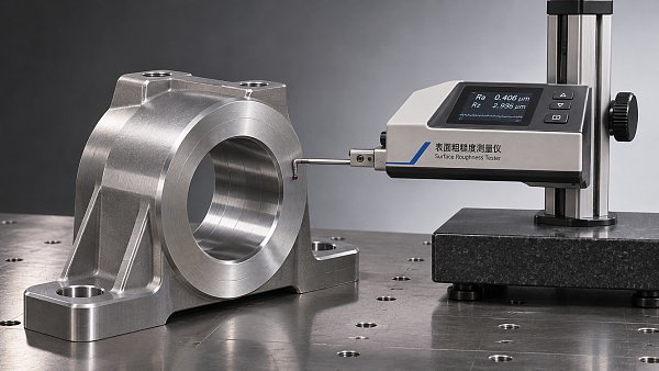
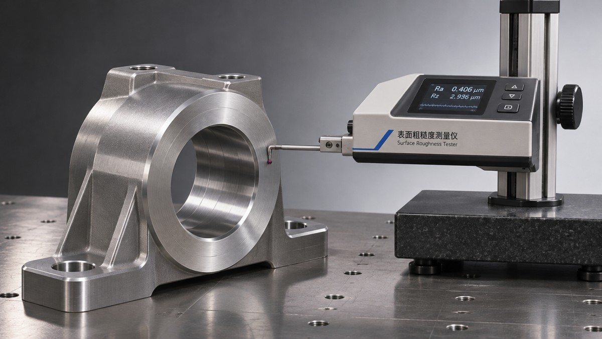
Ra is an arithmetic average of the absolute profile deviations from a mean line over the evaluation length. It is useful for describing average profile roughness, but the averaging process suppresses information about the distribution of peaks and valleys. Two surfaces with the same Ra can have different scratch patterns, isolated deep grooves, or peak characteristics.
Rz describes profile height using peak-to-valley information, but its calculation and interpretation depend on the specified standard and its edition. An Rz value copied from an older drawing or an instrument report cannot be compared safely with another value until the parameter definition and evaluation settings are aligned. There is no universal conversion factor from Ra to Rz: the relationship changes with the surface profile.
Consider a ground bearing seat and a turned seat with the same Ra. Their directional marks and valley shapes can differ, affecting lubrication and contact behavior. A sealing surface introduces another concern: a single scratch crossing the sealing path can matter even when the reported average roughness passes. A drawing that calls out only Ra may therefore leave a functional defect insufficiently controlled.
Roughness is one part of surface texture. Waviness, often associated with longer-spatial-scale variation, can affect contact over a larger area even when a short roughness trace is acceptable. Filtering separates parts of the measured profile by spatial scale; changing the filter or cutoff can change the reported result. The measurement setup must therefore follow the drawing’s applicable requirements rather than rely on an instrument’s default settings.
Measurement conditions determine whether results are comparable
A surface texture report should identify the parameter, applicable specification, sampling or cutoff settings, evaluation length, measurement direction, and instrument method. A stylus trace taken perpendicular to turning marks can produce a different result from one taken parallel to them. For a small feature, there may be insufficient uninterrupted length to use the intended settings; resolve that limitation before production rather than substitute a shorter trace without agreement.
Stylus access and tip geometry also matter. A stylus cannot necessarily reach the bottom of a narrow groove or trace a steep feature faithfully. Optical methods avoid physical contact but respond differently to reflectivity, steep slopes, and missing data. Results from contact and optical instruments should be compared only after their methods and the surface characteristics under evaluation have been established.
Dimensional inspection has its own sources of variation. Temperature affects the part, fixture, and measuring equipment; a part measured immediately after machining may still be cooling. Burrs can alter caliper readings, and excessive probing force can deflect thin walls. The number and distribution of measurement points must suit the feature: a single diameter reading cannot establish roundness, and a few points on a large face may miss a local high spot.
Uncertainty and acceptance near a limit
Every measurement has uncertainty. When a reported value lies close to a specification limit, a pass or fail decision can change with the instrument, setup, or decision rule. Establish whether the acceptance rule uses the measured value directly or applies a guard band, and agree on the treatment of uncertainty before inspecting borderline parts. A more precise display does not, by itself, reduce uncertainty.
For a critical bore, a useful inspection record identifies the instrument, calibration status, environmental conditions, measurement locations, and result. If the bore is checked only at its accessible end, the result does not establish that the full depth satisfies the requirement. The same principle applies to internal surfaces: access constraints must be considered when the requirement is written.
Machining capability is a combination of part and process
A stated machine positioning capability does not establish the tolerance achievable on every part. The finished feature reflects tool deflection, workholding, thermal behavior, material response, tool wear, cutting forces, and the sequence used to remove material. A short, rigid bore in a stable block presents a different task from a deep bore in a thin-walled housing, even when both have the same nominal diameter.
Material behavior changes the achievable result. Heat-resistant alloys can place demanding loads on tools and retain heat near the cutting zone; tool wear and heat must be controlled to maintain both size and surface condition. Softer materials can form burrs or deform under clamping. Residual stresses released during material removal can move a previously machined surface, making roughing, rest periods, and finishing sequence relevant to the final geometry.
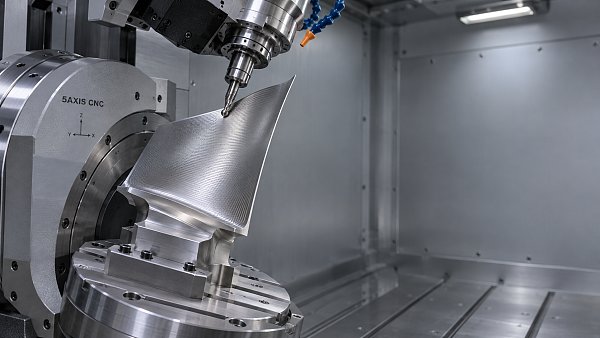
Five-axis access can reduce the need to reposition a complex part, but the final error still includes machine geometry, setup, tool length, and probing or inspection strategy. Fewer setups do not automatically guarantee better feature-to-feature accuracy. Conversely, a carefully controlled multi-setup process can meet a demanding requirement when the datum transfer and workholding are appropriate.
Surface finish follows a different set of tradeoffs from dimensional size. Feed, tool nose geometry, vibration, tool condition, and material behavior influence the resulting texture. Reducing feed can change the theoretical tool-mark spacing, yet chatter or a damaged cutting edge can still dominate the measured finish. A polished surface can lower a roughness reading while changing an edge, altering a profile, or removing material unevenly.
Use capability evidence in context
A single conforming sample demonstrates that the measured part met the stated requirements under the recorded conditions. It does not establish how consistently a process will perform over a production run. Meaningful capability evidence includes the actual feature and tolerance, material and process, measurement system, sampling plan, and results collected across relevant sources of variation, such as tool changes or shifts.
Capability indices such as Cp and Cpk are useful only when their underlying data and assumptions are suitable. Their interpretation depends on the specification limits, process behavior, sample design, and method used to estimate variation. A high index for an easily accessed external diameter cannot be transferred to a deep internal feature or a different material. If the process is unstable, a single index can conceal drift or intermittent defects.
When comparing results, distinguish machine capability, process capability, and inspection capability. A machine test performed under controlled conditions describes one part of the system. Production results include fixtures, tools, programming, material, and handling. Inspection capability concerns whether the measurement system can resolve the variation and support the acceptance decision. Each answers a different question.
Make a drawing measurable before releasing it
Assign tight controls to features whose function requires them, then define their relationship to the rest of the part. A bearing bore may need a size limit, form control, and alignment to a mounting datum; an adjacent clearance pocket may not. Applying the same tolerance everywhere can obscure the features that actually govern assembly.
For surface finish, identify the affected surfaces and specify the parameter and applicable measurement convention. Add lay, waviness, or defect requirements where the application calls for them. A gasket face, sliding guide, and cosmetic exterior can require different controls even when they are produced in the same setup.
Finally, resolve inspection access and acceptance criteria with the drawing. A requirement that cannot be measured on the finished part may need an alternative inspection method, a witness feature, or a defined process control. Recording that agreement before machining creates a basis for interpreting results when a measurement falls near a limit.
Search News
Hot Articles
- Carbon Fiber StructuresHow to Specify Aerospace Carbon Fiber Assemblies for Lightweight, Load-Bearing PartsJul 11, 2026
- Machine VisionXiaomi, Alibaba DAMO Academy Drive Open-Source Robotics Model Ecosystem, Lowering Algorithm Development Barriers for Overseas SMEs Adopting Chinese Robotics SolutionsMar 30, 2026
- Cobots & ArmsShanxi 'AI+' Conference Showcases Embodied Intelligence with Multinational Buyer Engagement: Key Industry ImplicationsMar 30, 2026
Popular Tags
Recommended News
 Jul 11, 2026How to Specify Aerospace Carbon Fiber Assemblies for Lightweight, Load-Bearing PartsAerospace carbon fiber assemblies: learn how to specify laminate design, load data, joining methods, and inspection controls for lighter, reliable load-bearing aerospace parts.Elena Rostova (UAV Systems Researcher)
 Mar 30, 2026Xiaomi, Alibaba DAMO Academy Drive Open-Source Robotics Model Ecosystem, Lowering Algorithm Development Barriers for Overseas SMEs Adopting Chinese Robotics SolutionsXiaomi & Alibaba DAMO Academy's open-source robotics models lower algorithm barriers for global SMEs. Boost efficiency in manufacturing, logistics & smart retail with ROS 2 compatible solutions.TSV Data Lab
 Mar 30, 2026Shanxi 'AI+' Conference Showcases Embodied Intelligence with Multinational Buyer Engagement: Key Industry ImplicationsShanxi 'AI+' Conference highlights embodied intelligence with Tesla, Ubtech & Jiantao showcasing multimodal robotics. 40+ global buyers validated tech on-site, creating new B2B channels for industrial automation & AI solutions.Chen Wei (Automation Lead Engineer)
 Mar 30, 2026Zhongguancun Unveils 6G Integrated Sensing-Computing-Intelligence Platform to Empower Embodied Robots for Global Industrial ApplicationsZhongguancun's new 6G platform revolutionizes industrial robotics with <10ms latency, empowering global automotive, logistics & port automation. Discover how this tech boosts China's smart manufacturing exports.TSV Data Lab
 Mar 30, 2026Mech-Mind Tianjin Embodied Intelligence R&D and Production Base Goes Live, Cutting Delivery Time by 20%–30% for Global Customized AMR+Vision SolutionsMech-Mind's Tianjin AMR+Vision production base cuts delivery time by 20%-30% for欧美 & Latin American markets. Discover how this PLd-certified facility accelerates customized robotics solutions for smart manufacturing and logistics.Chen Wei (Automation Lead Engineer)
 Mar 30, 2026Boao Forum Reveals 'Co-evolution of Big and Small Brains' Trend in Humanoid Robots, China's Embodied Intelligence Accelerates Adaptation to Overseas Manufacturing Service ScenariosDiscover how China's humanoid robots, featuring 'Co-evolution of Big and Small Brains,' are revolutionizing global manufacturing. Learn about Embodied Tian Gong 3.0's ISO compliance and overseas deployment at Boao Forum 2026.Chen Wei (Automation Lead Engineer)
 Mar 30, 2026China Railway Industrial Secures Patent for Embodied Robotics in Material Handling, Boosting High-Precision Delivery Capabilities for Overseas Infrastructure and Manufacturing ProjectsChina Railway Industrial's new patent for embodied robotics in material handling boosts high-precision delivery for global infrastructure & manufacturing. Discover how this innovation enhances logistics accuracy in automotive, rail transit & EPC projects.Chen Wei (Automation Lead Engineer)
 Nov 19, 2026Choosing a Palletizing System for Bagged Food: Speed and Bag HandlingChoose the right palletizing system for bagged food. Compare throughput, bag handling, food safety, and robotic vs. conventional options.Chen Wei (Automation Lead Engineer)
 Nov 18, 2026Formnext 2026 Opens as Additive Manufacturing Advances Industrial ApplicationsFormnext 2026 highlights additive manufacturing innovations for industrial applications. Explore what they could mean for production, procurement and suppliers.Dr. Marcus Vance
 Nov 18, 2026Flexible Robotics Integration for High-Mix, Low-Volume ProductionFlexible robotics integration can make high-mix, low-volume production more adaptable. Explore practical ways to reduce changeover risk and plan a reliable robotic cell.Victor Lin (Chief Software Architect)
 Nov 17, 2026Formnext 2026: UK Additive Manufacturing Leads in Research but Faces Production BarriersUK additive manufacturing leads in research but faces barriers to production at scale. Explore the Formnext 2026 insights and what businesses should consider.Dr. Marcus Vance
 Nov 17, 2026Choosing Warehouse Automation Packaging Systems: Throughput and SpaceCompare warehouse automation packaging systems by throughput, footprint, and order mix. Discover how to choose a layout that meets peak demand.Victor Lin (Chief Software Architect)
 Nov 16, 2026China's October Industrial Robot Output Up 26%, 3D Printing Equipment Up 85.9%China's industrial robot output reportedly rose 26% in October, while 3D printing equipment grew 85.9%. Explore what the figures could mean for buyers.Chen Wei (Automation Lead Engineer)
 Nov 16, 2026Commercial Drones in North America: Choosing Payloads for Inspection and MappingCommercial drones North America: compare RGB, thermal and LiDAR payloads for inspection and mapping, and choose a system that delivers reliable data.Elena Rostova (UAV Systems Researcher)
 Nov 15, 2026Aerospace Materials in the UK: Choosing Metals and Composites for AircraftExplore aerospace materials UK teams use for aircraft. Compare metals and composites by weight, fatigue, manufacturing and approval needs to make informed choices.Dr. Marcus Vance
 Nov 14, 2026Ukraine Tests 3D-Printed Protective Structure Against M2 Heavy Machine-Gun FireUkraine’s 3D-printed protective structure reportedly resisted M2 heavy machine-gun fire. Explore the test’s limits and potential procurement implications.Dr. Marcus Vance
 Nov 14, 2026Rugged UAV Metrics: Assessing Wind Resistance, Endurance and IP RatingsCompare rugged UAV metrics for wind resistance, endurance and IP ratings. Learn what evidence to request and choose a platform fit for your mission.Chen Wei (Automation Lead Engineer)
 Nov 13, 2026Physical AI Gains Attention as Robot Investment Moves Beyond HardwarePhysical AI is reshaping robot investment beyond hardware. Explore what the shift toward perception and algorithms could mean for buyers and suppliers.Chen Wei (Automation Lead Engineer)
 Nov 13, 2026Precision Machining Benchmarks: A Guide to Tolerances and Surface FinishExplore this precision machining benchmarks guide to compare tolerances, surface finish, and inspection methods—and specify parts with confidence.Dr. Marcus Vance
 Nov 12, 2026Beijing Issues Three-Year Plan for Embodied AI Robotics IndustryBeijing’s embodied AI robotics plan targets leading humanoid robot makers by 2028. Explore its goals for supply chains, AI models and deployment.Chen Wei (Automation Lead Engineer)
 Nov 12, 2026Choosing an Edge AI Box for Robotics: Compute, Latency and I/OChoose the right edge AI box for robotics with practical guidance on compute, latency, sensor I/O and sustained performance. Explore the selection checklist.Chen Wei (Automation Lead Engineer)
 Nov 11, 2026Beijing Sets 200,000-Unit Annual Capacity Goal in Robotics PlanBeijing's robotics plan targets 200,000 units of annual capacity by 2027. Explore its technology goals, benchmark applications and adoption outlook.Chen Wei (Automation Lead Engineer)
 Nov 11, 2026Aero Engine Blade Machining: 5-Axis CNC Methods and ChallengesExplore aero engine blade machining, from 5-axis toolpaths to thin-wall challenges, surface integrity, and inspection. Learn what makes a process reliable.Dr. Marcus Vance
 Nov 10, 2026FAA Authorizes Skyways’ Long-Distance BVLOS Flights for Shell in Gulf of MexicoFAA authorizes Skyways’ long-distance BVLOS drone flights for Shell in the Gulf of Mexico. Discover what the decision means for offshore pipeline inspection.Elena Rostova (UAV Systems Researcher)