Aero Engine Blade Machining: 5-Axis CNC Methods and Challenges
Publication Date
author
Aero engine blade machining demands more than a machine with five moving axes. Complex airfoil geometries, difficult-to-cut alloys, and stringent surface-integrity requirements make toolpath selection, process stability, and inspection critical to component performance. A credible capability claim must connect the machine, cutting process, workholding, inspection method, and approved acceptance criteria for the specific blade.
The central distinction is between producing an airfoil that appears geometrically correct and demonstrating a repeatable process that preserves its specified geometry and surface condition. Five-axis motion improves tool access, but it does not by itself control blade deflection, machining damage, thermal distortion, or measurement uncertainty.
Why blade geometry changes the machining problem
An engine blade combines features with different manufacturing priorities. The airfoil has a continuously changing curvature and may become very thin near its trailing edge. The root must locate and retain the blade in the disk, often through a fir-tree or dovetail form. Platforms, shrouds, and cooling features may add further access and datum constraints. Not every blade has all of these features, and their requirements depend on its location and design.
These features cannot be evaluated independently. Airfoil position and orientation are meaningful only in relation to the drawing’s datum system, which may be established using root or platform features. A smooth airfoil measured in isolation can still fail if its twist, location, or relationship to the root falls outside the specified limits.
Manufacturing route matters as well. A blade machined from wrought stock presents a different stock-removal problem from a precision casting that receives machining only on selected surfaces. Some components include internal cooling passages formed before final machining or produced using separate processes. A five-axis milling capability should not be assumed to cover casting, cooling-hole production, coating, or final finishing.
How five-axis motion is used on an airfoil
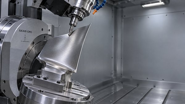
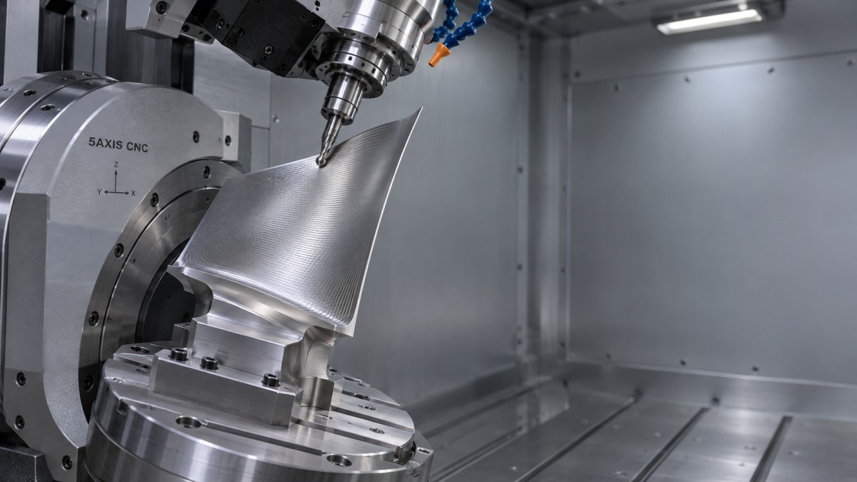
In simultaneous five-axis milling, three linear axes and two rotary axes move together so the cutter can follow the surface while its orientation changes. The programmed contact point, tool-axis direction, feed rate, and machine kinematics must all remain compatible. The objective is not simply to keep the cutter normal to the surface: the chosen orientation must also avoid collisions, maintain effective cutting conditions, and stay within rotary-axis travel and dynamic limits.
For airfoil finishing, ball-nose tools can reach complex concave and convex regions, but their contact conditions vary with tool tilt. Cutting near the center of a ball nose gives a low effective cutting speed; excessive tilt can introduce clearance or gouging problems. Barrel or other circle-segment cutters can cover suitable surfaces with a larger effective cutting radius, potentially reducing the number of passes for a given theoretical scallop height. Their benefit depends on surface curvature, access, tool geometry, and the CAM system’s ability to calculate a collision-free path.
A smaller stepover can reduce geometric scallops, but it does not guarantee an acceptable surface. Tool vibration, runout, edge condition, material behavior, and machine dynamics also affect the resulting texture. A surface that meets a roughness limit may still contain localized damage or machining marks with an unfavorable orientation.
Not every operation requires simultaneous five-axis motion. In indexed, or 3+2, machining, the rotary axes position the part or tool and remain fixed while the linear axes cut. This can simplify programming and provide stable access for features that do not require continuously changing orientation. Its limitations appear where an indexed setup cannot maintain suitable cutter engagement or reach the surface without interference.
Root features may be produced through a separate milling, broaching, grinding, or other qualified operation, depending on the design and production route. Their inspection should therefore be linked to the same datum scheme used to assess the airfoil. A successful airfoil finishing cycle alone does not demonstrate capability for the complete blade.
Material removal and the thin-wall problem
Titanium alloys and nickel-based superalloys create different but related cutting challenges. Titanium’s low thermal conductivity concentrates heat near the cutting zone, while its relatively low stiffness makes tool and part deflection important. Nickel-based superalloys can retain strength at elevated temperature and impose substantial thermal and mechanical loads on the cutting edge. The applicable alloy condition, tooling, cutting parameters, and coolant strategy all influence the outcome.
Workhardening and tool wear also change the process as a batch progresses. A cutting condition that produces an acceptable first part does not establish performance at the end of a tool’s permitted life. Evidence should connect tool-life limits and replacement criteria to the features and surface conditions they affect, rather than relying only on elapsed cutting time.
Blade stiffness changes as material is removed. A roughing strategy that is stable while the blank is rigid can become unsuitable when the remaining airfoil is thin. Cutting forces may bend the part away from the tool; after the load is removed, the surface springs back, leaving a form error. The error may vary along the span and between the pressure and suction sides.
One response is to retain material strategically during roughing, then remove the remaining stock in a controlled sequence that preserves support. Balanced stock removal, appropriate fixture support, reduced finishing forces, and consistent tool condition can all contribute. None is universally sufficient: support that reduces deflection can itself distort the blade if clamping force or contact location is poorly controlled.
Verification should therefore consider the blade in more than one state. An in-process measurement made while the part is clamped can be useful for detecting drift, but it may not reveal the shape after release. If the acceptance condition requires a free-state or otherwise specified setup, the final inspection must reproduce that condition.
Surface integrity is more than roughness
Surface integrity includes the condition of the material affected by machining, not just its visible finish. Depending on the alloy and operation, excessive cutting heat or mechanical loading can contribute to microstructural changes, residual stress, tearing, smearing, or other damage. These conditions matter because blades experience cyclic loading, and component performance depends on more than nominal dimensions.
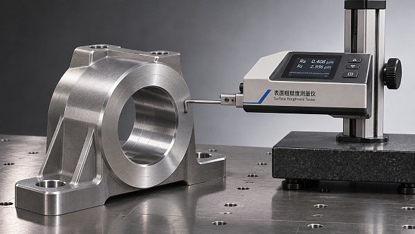
The controlling requirements must come from the drawing, material specification, process specification, and approved manufacturing route. A roughness value alone does not establish the absence of subsurface damage. Conversely, a visual mark is not automatically a rejectable defect unless the applicable criteria make it one. The evaluation must distinguish measurable requirements from assumptions about what a good surface should look like.
Where a process specification requires tests such as metallographic examination, those tests need a defined sampling plan and acceptance criteria. Results from a qualification coupon or initial trial should be tied to the material, tooling, parameters, and operation it represents. Changing a cutter grade, coolant delivery method, finishing allowance, or tool-life limit can change the cutting conditions that produced the original evidence.
Deburring and edge finishing deserve similar attention. A trailing edge or specified edge radius can be affected by manual intervention after CNC machining. If hand finishing is permitted, its controls and final inspection need to demonstrate that the finished feature still meets the drawing rather than relying on the programmed cutter path as proof.
Machine capability must be demonstrated at the part
Machine positioning and rotary-axis performance influence blade accuracy, but a catalog accuracy figure is not the same as an achievable airfoil tolerance. The result depends on machine geometry, thermal state, fixture location, tool length, calibration, controller behavior, cutting forces, and the postprocessed program. Long tool overhangs or unfavorable rotary positions can make a nominally capable machine unsuitable for a particular feature.
Rotary-axis behavior is especially relevant where the toolpath passes near a kinematic singularity or demands rapid angular movement. The controller may slow the feed, change the motion profile, or produce a less favorable surface if the programmed orientation is poorly selected. Simulation can identify potential travel and collision problems, but a simulation result alone does not establish the actual surface or dimensional outcome.
A useful capability demonstration therefore uses the relevant geometry, material condition, fixture, tool assembly, and production sequence. It should include results across an appropriately defined run, not just the best component. Where statistical capability indices are supplied, their interpretation depends on the sampling method, measurement system, process stability, and whether the characteristic is suitable for that analysis.
Inspection must preserve the drawing’s intent
Airfoil inspection often combines coordinate measurement or scanning with analysis against the nominal model and drawing. The critical question is how the measured data are aligned. A best-fit alignment can help diagnose surface shape, but it can also obscure a positional or rotational error if the drawing requires evaluation relative to specified datums. The report should make the alignment method explicit and apply the method required for acceptance.
Point density and distribution also matter. Sparse sampling can miss local form deviations, while a dense scan is not automatically accurate: probe accessibility, optical line of sight, surface condition, calibration, and data processing affect the result. Leading and trailing edges, tight radii, and transitions into the platform can require particular attention because they are difficult both to machine and to measure.
Measurement uncertainty should be considered against the tolerance and the applicable decision rule. A reported pass close to a tolerance boundary is less informative if the measurement method, environmental conditions, or fixture repeatability are poorly characterized. On-machine probing is valuable for setup and process control, but independent final measurement may still be required by the control plan or customer specification.
Relevant standards need to be interpreted correctly. AS9100 is an aerospace quality management system standard; it does not prescribe a universal blade-machining tolerance or certify a particular machine’s accuracy. Geometric tolerancing and measurement requirements depend on the standards and editions invoked by the drawing or contract, along with any engine manufacturer’s specifications. Certification status cannot replace evidence that a specific blade and process meet those requirements.
What constitutes convincing process evidence
A meaningful technical review connects each claim to a defined characteristic and its acceptance method. For example, an airfoil form result should identify the datum alignment, measurement coverage, tolerance, inspection condition, and reporting method. A surface-integrity claim should identify the controlled operation and any examinations required by the applicable specification.
The evidence package is stronger when it shows the relationship between:
- Part definition: drawing revision, material condition, datum scheme, and applicable customer requirements.
- Manufacturing controls: operation sequence, fixture, tooling, programmed parameters, tool-life limits, and controls for process changes.
- Inspection: characteristic-specific methods, measurement alignment, equipment status, sampling, and treatment of uncertainty where applicable.
- Production consistency: records that show how variation, nonconformities, and corrective actions are managed across the defined run.
The decisive question is not whether a supplier owns a five-axis machine or can produce one visually convincing blade. It is whether the specified features and surface condition can be achieved, measured, and maintained under a controlled process whose scope matches the component being evaluated.
Search News
Hot Articles
- Carbon Fiber StructuresHow to Specify Aerospace Carbon Fiber Assemblies for Lightweight, Load-Bearing PartsJul 11, 2026
- Machine VisionXiaomi, Alibaba DAMO Academy Drive Open-Source Robotics Model Ecosystem, Lowering Algorithm Development Barriers for Overseas SMEs Adopting Chinese Robotics SolutionsMar 30, 2026
- Cobots & ArmsShanxi 'AI+' Conference Showcases Embodied Intelligence with Multinational Buyer Engagement: Key Industry ImplicationsMar 30, 2026
Popular Tags
Recommended News
 Jul 11, 2026How to Specify Aerospace Carbon Fiber Assemblies for Lightweight, Load-Bearing PartsAerospace carbon fiber assemblies: learn how to specify laminate design, load data, joining methods, and inspection controls for lighter, reliable load-bearing aerospace parts.Elena Rostova (UAV Systems Researcher)
 Mar 30, 2026Xiaomi, Alibaba DAMO Academy Drive Open-Source Robotics Model Ecosystem, Lowering Algorithm Development Barriers for Overseas SMEs Adopting Chinese Robotics SolutionsXiaomi & Alibaba DAMO Academy's open-source robotics models lower algorithm barriers for global SMEs. Boost efficiency in manufacturing, logistics & smart retail with ROS 2 compatible solutions.TSV Data Lab
 Mar 30, 2026Shanxi 'AI+' Conference Showcases Embodied Intelligence with Multinational Buyer Engagement: Key Industry ImplicationsShanxi 'AI+' Conference highlights embodied intelligence with Tesla, Ubtech & Jiantao showcasing multimodal robotics. 40+ global buyers validated tech on-site, creating new B2B channels for industrial automation & AI solutions.Chen Wei (Automation Lead Engineer)
 Mar 30, 2026Zhongguancun Unveils 6G Integrated Sensing-Computing-Intelligence Platform to Empower Embodied Robots for Global Industrial ApplicationsZhongguancun's new 6G platform revolutionizes industrial robotics with <10ms latency, empowering global automotive, logistics & port automation. Discover how this tech boosts China's smart manufacturing exports.TSV Data Lab
 Mar 30, 2026Mech-Mind Tianjin Embodied Intelligence R&D and Production Base Goes Live, Cutting Delivery Time by 20%–30% for Global Customized AMR+Vision SolutionsMech-Mind's Tianjin AMR+Vision production base cuts delivery time by 20%-30% for欧美 & Latin American markets. Discover how this PLd-certified facility accelerates customized robotics solutions for smart manufacturing and logistics.Chen Wei (Automation Lead Engineer)
 Mar 30, 2026Boao Forum Reveals 'Co-evolution of Big and Small Brains' Trend in Humanoid Robots, China's Embodied Intelligence Accelerates Adaptation to Overseas Manufacturing Service ScenariosDiscover how China's humanoid robots, featuring 'Co-evolution of Big and Small Brains,' are revolutionizing global manufacturing. Learn about Embodied Tian Gong 3.0's ISO compliance and overseas deployment at Boao Forum 2026.Chen Wei (Automation Lead Engineer)
 Mar 30, 2026China Railway Industrial Secures Patent for Embodied Robotics in Material Handling, Boosting High-Precision Delivery Capabilities for Overseas Infrastructure and Manufacturing ProjectsChina Railway Industrial's new patent for embodied robotics in material handling boosts high-precision delivery for global infrastructure & manufacturing. Discover how this innovation enhances logistics accuracy in automotive, rail transit & EPC projects.Chen Wei (Automation Lead Engineer)
 Nov 19, 2026Choosing a Palletizing System for Bagged Food: Speed and Bag HandlingChoose the right palletizing system for bagged food. Compare throughput, bag handling, food safety, and robotic vs. conventional options.Chen Wei (Automation Lead Engineer)
 Nov 18, 2026Formnext 2026 Opens as Additive Manufacturing Advances Industrial ApplicationsFormnext 2026 highlights additive manufacturing innovations for industrial applications. Explore what they could mean for production, procurement and suppliers.Dr. Marcus Vance
 Nov 18, 2026Flexible Robotics Integration for High-Mix, Low-Volume ProductionFlexible robotics integration can make high-mix, low-volume production more adaptable. Explore practical ways to reduce changeover risk and plan a reliable robotic cell.Victor Lin (Chief Software Architect)
 Nov 17, 2026Formnext 2026: UK Additive Manufacturing Leads in Research but Faces Production BarriersUK additive manufacturing leads in research but faces barriers to production at scale. Explore the Formnext 2026 insights and what businesses should consider.Dr. Marcus Vance
 Nov 17, 2026Choosing Warehouse Automation Packaging Systems: Throughput and SpaceCompare warehouse automation packaging systems by throughput, footprint, and order mix. Discover how to choose a layout that meets peak demand.Victor Lin (Chief Software Architect)
 Nov 16, 2026China's October Industrial Robot Output Up 26%, 3D Printing Equipment Up 85.9%China's industrial robot output reportedly rose 26% in October, while 3D printing equipment grew 85.9%. Explore what the figures could mean for buyers.Chen Wei (Automation Lead Engineer)
 Nov 16, 2026Commercial Drones in North America: Choosing Payloads for Inspection and MappingCommercial drones North America: compare RGB, thermal and LiDAR payloads for inspection and mapping, and choose a system that delivers reliable data.Elena Rostova (UAV Systems Researcher)
 Nov 15, 2026Aerospace Materials in the UK: Choosing Metals and Composites for AircraftExplore aerospace materials UK teams use for aircraft. Compare metals and composites by weight, fatigue, manufacturing and approval needs to make informed choices.Dr. Marcus Vance
 Nov 14, 2026Ukraine Tests 3D-Printed Protective Structure Against M2 Heavy Machine-Gun FireUkraine’s 3D-printed protective structure reportedly resisted M2 heavy machine-gun fire. Explore the test’s limits and potential procurement implications.Dr. Marcus Vance
 Nov 14, 2026Rugged UAV Metrics: Assessing Wind Resistance, Endurance and IP RatingsCompare rugged UAV metrics for wind resistance, endurance and IP ratings. Learn what evidence to request and choose a platform fit for your mission.Chen Wei (Automation Lead Engineer)
 Nov 13, 2026Physical AI Gains Attention as Robot Investment Moves Beyond HardwarePhysical AI is reshaping robot investment beyond hardware. Explore what the shift toward perception and algorithms could mean for buyers and suppliers.Chen Wei (Automation Lead Engineer)
 Nov 13, 2026Precision Machining Benchmarks: A Guide to Tolerances and Surface FinishExplore this precision machining benchmarks guide to compare tolerances, surface finish, and inspection methods—and specify parts with confidence.Dr. Marcus Vance
 Nov 12, 2026Beijing Issues Three-Year Plan for Embodied AI Robotics IndustryBeijing’s embodied AI robotics plan targets leading humanoid robot makers by 2028. Explore its goals for supply chains, AI models and deployment.Chen Wei (Automation Lead Engineer)
 Nov 12, 2026Choosing an Edge AI Box for Robotics: Compute, Latency and I/OChoose the right edge AI box for robotics with practical guidance on compute, latency, sensor I/O and sustained performance. Explore the selection checklist.Chen Wei (Automation Lead Engineer)
 Nov 11, 2026Beijing Sets 200,000-Unit Annual Capacity Goal in Robotics PlanBeijing's robotics plan targets 200,000 units of annual capacity by 2027. Explore its technology goals, benchmark applications and adoption outlook.Chen Wei (Automation Lead Engineer)
 Nov 11, 2026Aero Engine Blade Machining: 5-Axis CNC Methods and ChallengesExplore aero engine blade machining, from 5-axis toolpaths to thin-wall challenges, surface integrity, and inspection. Learn what makes a process reliable.Dr. Marcus Vance
 Nov 10, 2026FAA Authorizes Skyways’ Long-Distance BVLOS Flights for Shell in Gulf of MexicoFAA authorizes Skyways’ long-distance BVLOS drone flights for Shell in the Gulf of Mexico. Discover what the decision means for offshore pipeline inspection.Elena Rostova (UAV Systems Researcher)