Retrofitting Quality Inspection Automation on Existing Production Lines
Publication Date
author
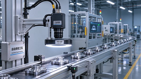
Retrofitting quality inspection automation can improve defect detection without rebuilding an entire production line, but the decisive constraint is rarely the camera alone. A viable installation must create a repeatable view of the product, make a decision within the available cycle time, and reliably connect that decision to the correct physical item.
The strongest investment case starts with a specific inspection gap and a realistic assessment of the existing line. If product presentation is unstable, defects are poorly defined, or there is no dependable way to isolate rejected parts, adding an inspection system may automate uncertainty rather than improve quality.
Define the inspection decision before selecting equipment
Begin with the decision the line must make: which product or feature is being inspected, which conditions constitute a defect, and what should happen when an item fails. “Improve quality” is not a testable requirement. “Identify missing seals before assembly and prevent the affected unit from advancing” is closer to one.
Translate that decision into an inspection specification covering the defect type, its minimum relevant size or severity, its location, and the acceptable variation between products. Include examples near the acceptance boundary, not only obvious failures. A scratch that matters on a sealing surface may be irrelevant on a concealed area; the imaging system and acceptance rules need to reflect that distinction.
Separate defect detection from the subsequent operational response. A system may correctly identify a defect but still fail to protect the customer if it cannot track the item to a reject station. Conversely, diverting every uncertain part can protect the downstream process while creating a costly manual-review queue. The project requirements should therefore address both the inspection result and the disposition of the product.
Establish a baseline using existing inspection records where they are reliable, supplemented by a representative manual assessment where necessary. Document current escapes, false rejects, rework, inspection labor and throughput using consistent definitions. Existing records can understate the true defect rate if defects are not routinely confirmed or if downstream escapes cannot be traced to the line.
Find an inspection point that the line can support
The best point for inspection is not necessarily where a camera fits most easily. It is where the relevant feature is visible, product position is sufficiently controlled, and there is still a practical way to act on the result. Inspecting before a component is covered may improve visibility; inspecting after an operation may be necessary to confirm that the operation was completed correctly.
Survey the proposed location under normal operating conditions, including changeovers and cleaning. The assessment should cover:
- Mechanical access: mounting space, guarding, vibration, product movement and access for cleaning or maintenance.
- Presentation: part orientation, height variation, conveyor spacing and whether fixtures or guides can make the view repeatable.
- Environment: ambient light, dust, moisture, temperature and contamination that could change the image over a shift.
- Line interfaces: available sensors, controller signals, network capacity, power and the means of associating each result with a specific item.
- Product flow: distance to the reject point, accumulation behavior, variable speed and what happens when the line stops or reverses.
A stable fixture, controlled lighting enclosure or modest guide-rail change can be more valuable than a more sophisticated algorithm. These mechanical changes also have consequences: a guide that improves imaging must not damage the product, create a jam point or interfere with changeover.
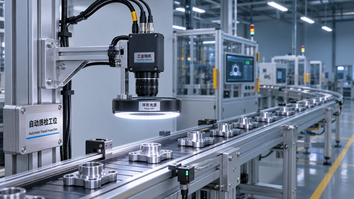
Where no single position exposes every required feature, the choices include multiple views, reorienting the part, inspecting at separate stations or retaining a manual check for the inaccessible feature. A partial automated inspection can be worthwhile, provided the remaining coverage gap is explicit in the quality plan.
Choose the measurement method around the defect
Machine vision is useful when a defect produces a visible and sufficiently repeatable image difference. It is not a universal substitute for measurement. An internal defect, a material property or a feature hidden from view may require another sensing method or a separate inspection operation.
For visible features, evaluate the complete imaging chain rather than a camera specification in isolation. The field of view, lens, sensor resolution, working distance, lighting and exposure all determine whether the defect is distinguishable. A simple starting estimate is:
Image scale = field-of-view width ÷ image width in pixels.
If a 100 mm-wide view is represented by 2,000 pixels, the nominal scale is 0.05 mm per pixel. That does not mean the system can reliably detect or measure every 0.05 mm defect. Detection depends on contrast, focus, motion blur, optical distortion, defect orientation and how many pixels are needed to distinguish the feature from normal variation. The required margin must be established through representative testing.
Lighting often determines whether the target feature is visible at all. Diffuse light can reduce glare on reflective surfaces; directional lighting can emphasize texture or edges; backlighting can help reveal a silhouette. Each arrangement changes which defects stand out and which may disappear. Test with the actual material finish, expected color range and realistic contamination, not only clean samples under laboratory conditions.
Rule-based image processing can be appropriate for stable features with clear geometry or contrast. A trained classification model may be useful when acceptable appearance varies and defects are difficult to express as fixed rules. Neither approach removes the need for representative samples and a controlled acceptance definition. For a trained model, separate development images from validation images and include different batches, positions and operating conditions to reduce the risk of an apparently strong result that fails on the line.
Design the timing and control logic as one system
The inspection must complete in time for the line to act. The relevant limit is not just image-processing speed: it includes trigger uncertainty, exposure, image transfer, computation, communication with the controller and the response time of the reject mechanism. The available decision window depends on the line speed and the distance between the inspection point and the point where intervention must occur.
For a continuously moving line, a useful initial calculation is:
Available travel time = distance from inspection to intervention ÷ product speed.
This is a planning estimate, not an acceptance test. The design must also allow for speed changes, variable part spacing, signal delays and the physical travel time of the reject device. If the margin is too small, moving the inspection point upstream or adding controlled spacing may be more effective than selecting a faster processor.
Define how the system identifies each product between inspection and rejection. A position encoder or another tracking method may be needed when speed varies; a fixed time delay alone can send the wrong item to reject if the conveyor stops or accelerates. Specify what happens when a product is missing, a sensor misses a trigger, the inspection returns no result, or a rejected item is not confirmed at the reject station.
The failure response should reflect the risk of releasing an uninspected product. Depending on the process, this could mean stopping the line, diverting affected items or placing a defined group of products on hold for review. A reject-bin-full signal, an operator override and a restart procedure are operational requirements, not minor software details.
Validate against production conditions, not demonstration images
Before committing to installation, run a feasibility study using samples that represent both normal variation and relevant defects. Record which defect categories are included, how their true condition was established, and which are missing from the sample set. Rare defects deserve particular attention: a small number of available examples limits confidence even when every example is detected.
Acceptance criteria should distinguish at least two outcomes: defective items accepted by the system and conforming items rejected by it. Report the counts behind the percentages and break results down by defect category, product variant and operating condition. A single overall accuracy figure can conceal poor performance on a rare but consequential defect, especially when most inspected items are good.
Include repeatability checks by presenting the same items multiple times across expected position and lighting variation. For dimensional measurements, compare results with a suitable reference method and assess measurement variation; a reliable pass/fail classifier is not automatically a reliable gauge. Set tolerances and decision thresholds using the product requirement and measurement uncertainty, rather than assuming that nominal pixel scale equals measurement capability.
A staged trial can expose integration issues without immediately putting automated rejection in control:
- Offline feasibility: confirm that the target features can be imaged and that candidate methods distinguish representative conditions.
- Shadow operation: run the system on the line while retaining the existing disposition process; compare results with independently reviewed outcomes.
- Controlled rejection: enable automatic action with agreed monitoring, escalation and a documented fallback.
- Production acceptance: demonstrate performance over an agreed period that includes relevant shifts, product variants and normal interruptions.
Shadow results are only meaningful if the reference decisions are dependable. Where inspectors disagree about borderline defects, resolve the acceptance rule before treating either the human or automated result as ground truth. Record exceptions and retest after changes to lighting, fixtures, software or thresholds.
Plan the shutdown, handover and ownership
A retrofit schedule should separate work that can be completed off-line from work requiring line access. Fabricating brackets, configuring software and testing controller interfaces in advance can reduce shutdown exposure, but the plan still needs time for alignment, safety checks, commissioning and recovery if the installation fails.
Agree on the outage window and the conditions for returning to the previous inspection method. The rollback plan should identify which wiring or mechanical changes can be reversed, who authorizes a return to production, and how products made during an uncertain inspection period will be contained. Changes to guards, electrical circuits or machine controls also require a site-specific safety assessment and compliance review before operation.
Assign ownership for each interface: mechanical mounting, electrical installation, controller programming, image-system configuration, reject hardware and quality acceptance. An unresolved boundary between suppliers and the site can leave the project with a working camera but no verified end-to-end reject function.
At handover, retain the approved configuration, wiring diagrams, software and model versions, calibration or verification procedures, spare-parts information and change-control rules. Define who can alter thresholds or retrain a model, what evidence is required before release, and how the team will recognize deterioration caused by dirty optics, shifted fixtures or product changes.
Build the financial case around verified effects
The cost of a quality inspection automation retrofit includes more than imaging hardware. Budget for fixtures, lighting, controls integration, safety work, installation, lost production during the outage, validation, training, maintenance and ongoing software support. Allow for the operational burden of reviewing uncertain results and disposing of false rejects.
Benefits should be tied to the baseline: reduced inspection effort that can actually be redeployed, fewer confirmed escapes, lower rework or scrap, and improved traceability where it has an identifiable value. Avoid counting the same avoided defect cost twice across scrap, warranty and labor categories. If an existing manual inspection must remain in place until sufficient evidence is available, its cost should remain in the early operating model.
A simple payback estimate divides total implementation cost by the annual net benefit, after recurring costs. Treat it as a scenario rather than a guarantee: recalculate it for different defect rates, false-reject levels, maintenance demands and production volumes. Some benefits, particularly avoidance of a serious escape, may be important but difficult to assign a defensible monetary value.
The go/no-go decision should rest on a complete chain of evidence: a detectable defect, a stable inspection point, sufficient timing margin, correct product tracking and an agreed response to uncertainty. If any link cannot be demonstrated, narrowing the inspection scope or retaining a controlled manual check may be the more reliable choice until the constraint is resolved.
Search News
Hot Articles
- Carbon Fiber StructuresHow to Specify Aerospace Carbon Fiber Assemblies for Lightweight, Load-Bearing PartsJul 11, 2026
- Machine VisionXiaomi, Alibaba DAMO Academy Drive Open-Source Robotics Model Ecosystem, Lowering Algorithm Development Barriers for Overseas SMEs Adopting Chinese Robotics SolutionsMar 30, 2026
- Cobots & ArmsShanxi 'AI+' Conference Showcases Embodied Intelligence with Multinational Buyer Engagement: Key Industry ImplicationsMar 30, 2026
Popular Tags
Recommended News
 Jul 11, 2026How to Specify Aerospace Carbon Fiber Assemblies for Lightweight, Load-Bearing PartsAerospace carbon fiber assemblies: learn how to specify laminate design, load data, joining methods, and inspection controls for lighter, reliable load-bearing aerospace parts.Elena Rostova (UAV Systems Researcher)
 Mar 30, 2026Xiaomi, Alibaba DAMO Academy Drive Open-Source Robotics Model Ecosystem, Lowering Algorithm Development Barriers for Overseas SMEs Adopting Chinese Robotics SolutionsXiaomi & Alibaba DAMO Academy's open-source robotics models lower algorithm barriers for global SMEs. Boost efficiency in manufacturing, logistics & smart retail with ROS 2 compatible solutions.TSV Data Lab
 Mar 30, 2026Shanxi 'AI+' Conference Showcases Embodied Intelligence with Multinational Buyer Engagement: Key Industry ImplicationsShanxi 'AI+' Conference highlights embodied intelligence with Tesla, Ubtech & Jiantao showcasing multimodal robotics. 40+ global buyers validated tech on-site, creating new B2B channels for industrial automation & AI solutions.Chen Wei (Automation Lead Engineer)
 Mar 30, 2026Zhongguancun Unveils 6G Integrated Sensing-Computing-Intelligence Platform to Empower Embodied Robots for Global Industrial ApplicationsZhongguancun's new 6G platform revolutionizes industrial robotics with <10ms latency, empowering global automotive, logistics & port automation. Discover how this tech boosts China's smart manufacturing exports.TSV Data Lab
 Mar 30, 2026Mech-Mind Tianjin Embodied Intelligence R&D and Production Base Goes Live, Cutting Delivery Time by 20%–30% for Global Customized AMR+Vision SolutionsMech-Mind's Tianjin AMR+Vision production base cuts delivery time by 20%-30% for欧美 & Latin American markets. Discover how this PLd-certified facility accelerates customized robotics solutions for smart manufacturing and logistics.Chen Wei (Automation Lead Engineer)
 Mar 30, 2026Boao Forum Reveals 'Co-evolution of Big and Small Brains' Trend in Humanoid Robots, China's Embodied Intelligence Accelerates Adaptation to Overseas Manufacturing Service ScenariosDiscover how China's humanoid robots, featuring 'Co-evolution of Big and Small Brains,' are revolutionizing global manufacturing. Learn about Embodied Tian Gong 3.0's ISO compliance and overseas deployment at Boao Forum 2026.Chen Wei (Automation Lead Engineer)
 Mar 30, 2026China Railway Industrial Secures Patent for Embodied Robotics in Material Handling, Boosting High-Precision Delivery Capabilities for Overseas Infrastructure and Manufacturing ProjectsChina Railway Industrial's new patent for embodied robotics in material handling boosts high-precision delivery for global infrastructure & manufacturing. Discover how this innovation enhances logistics accuracy in automotive, rail transit & EPC projects.Chen Wei (Automation Lead Engineer)
 Nov 20, 2026Retrofitting Quality Inspection Automation on Existing Production LinesQuality inspection automation retrofit: discover how to assess existing lines, integrate reliable detection and rejection, and build a sound investment case.Victor Lin (Chief Software Architect)
 Nov 19, 2026Choosing a Palletizing System for Bagged Food: Speed and Bag HandlingChoose the right palletizing system for bagged food. Compare throughput, bag handling, food safety, and robotic vs. conventional options.Chen Wei (Automation Lead Engineer)
 Nov 18, 2026Formnext 2026 Opens as Additive Manufacturing Advances Industrial ApplicationsFormnext 2026 highlights additive manufacturing innovations for industrial applications. Explore what they could mean for production, procurement and suppliers.Dr. Marcus Vance
 Nov 18, 2026Flexible Robotics Integration for High-Mix, Low-Volume ProductionFlexible robotics integration can make high-mix, low-volume production more adaptable. Explore practical ways to reduce changeover risk and plan a reliable robotic cell.Victor Lin (Chief Software Architect)
 Nov 17, 2026Formnext 2026: UK Additive Manufacturing Leads in Research but Faces Production BarriersUK additive manufacturing leads in research but faces barriers to production at scale. Explore the Formnext 2026 insights and what businesses should consider.Dr. Marcus Vance
 Nov 17, 2026Choosing Warehouse Automation Packaging Systems: Throughput and SpaceCompare warehouse automation packaging systems by throughput, footprint, and order mix. Discover how to choose a layout that meets peak demand.Victor Lin (Chief Software Architect)
 Nov 16, 2026China's October Industrial Robot Output Up 26%, 3D Printing Equipment Up 85.9%China's industrial robot output reportedly rose 26% in October, while 3D printing equipment grew 85.9%. Explore what the figures could mean for buyers.Chen Wei (Automation Lead Engineer)
 Nov 16, 2026Commercial Drones in North America: Choosing Payloads for Inspection and MappingCommercial drones North America: compare RGB, thermal and LiDAR payloads for inspection and mapping, and choose a system that delivers reliable data.Elena Rostova (UAV Systems Researcher)
 Nov 15, 2026Aerospace Materials in the UK: Choosing Metals and Composites for AircraftExplore aerospace materials UK teams use for aircraft. Compare metals and composites by weight, fatigue, manufacturing and approval needs to make informed choices.Dr. Marcus Vance
 Nov 14, 2026Ukraine Tests 3D-Printed Protective Structure Against M2 Heavy Machine-Gun FireUkraine’s 3D-printed protective structure reportedly resisted M2 heavy machine-gun fire. Explore the test’s limits and potential procurement implications.Dr. Marcus Vance
 Nov 14, 2026Rugged UAV Metrics: Assessing Wind Resistance, Endurance and IP RatingsCompare rugged UAV metrics for wind resistance, endurance and IP ratings. Learn what evidence to request and choose a platform fit for your mission.Chen Wei (Automation Lead Engineer)
 Nov 13, 2026Physical AI Gains Attention as Robot Investment Moves Beyond HardwarePhysical AI is reshaping robot investment beyond hardware. Explore what the shift toward perception and algorithms could mean for buyers and suppliers.Chen Wei (Automation Lead Engineer)
 Nov 13, 2026Precision Machining Benchmarks: A Guide to Tolerances and Surface FinishExplore this precision machining benchmarks guide to compare tolerances, surface finish, and inspection methods—and specify parts with confidence.Dr. Marcus Vance
 Nov 12, 2026Beijing Issues Three-Year Plan for Embodied AI Robotics IndustryBeijing’s embodied AI robotics plan targets leading humanoid robot makers by 2028. Explore its goals for supply chains, AI models and deployment.Chen Wei (Automation Lead Engineer)
 Nov 12, 2026Choosing an Edge AI Box for Robotics: Compute, Latency and I/OChoose the right edge AI box for robotics with practical guidance on compute, latency, sensor I/O and sustained performance. Explore the selection checklist.Chen Wei (Automation Lead Engineer)
 Nov 11, 2026Beijing Sets 200,000-Unit Annual Capacity Goal in Robotics PlanBeijing's robotics plan targets 200,000 units of annual capacity by 2027. Explore its technology goals, benchmark applications and adoption outlook.Chen Wei (Automation Lead Engineer)
 Nov 11, 2026Aero Engine Blade Machining: 5-Axis CNC Methods and ChallengesExplore aero engine blade machining, from 5-axis toolpaths to thin-wall challenges, surface integrity, and inspection. Learn what makes a process reliable.Dr. Marcus Vance