LiDAR field of view comparison for corridors, corners, and docks
Publication Date
author
Selecting the right sensing geometry starts with a rigorous lidar field of view comparison across corridors, corners, and docks, where blind spots, mounting height, and motion dynamics directly affect safety and mapping fidelity. For engineers, buyers, and operators evaluating agv lidar sensor supplier options, this guide also connects field-of-view tradeoffs with solid state lidar point cloud density and lidar sunlight interference resistance to support data-driven deployment decisions.
For most industrial mobile platforms, there is no single “best” LiDAR field of view. The correct choice depends on whether your vehicle spends most of its time in narrow corridors, negotiating blind corners, or aligning at docks. In practice, corridor navigation usually rewards stable forward coverage and side-wall consistency, corners demand earlier lateral visibility to reduce surprise obstacles, and docks require reliable close-range perception with minimal dead zones near the vehicle body. If you are comparing sensors or suppliers, the most important takeaway is this: field of view should never be evaluated alone. It must be assessed together with mounting height, occlusion behavior, point cloud density, sunlight robustness, and the actual stopping and turning behavior of the AGV or AMR.
What decision-makers are really trying to solve in a LiDAR field of view comparison
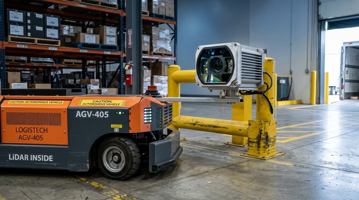
When users search for a lidar field of view comparison for corridors, corners, and docks, they are usually not looking for a theoretical definition of horizontal and vertical angles. They want to answer practical deployment questions:
- Will this sensor see enough of the path ahead in narrow aisles?
- Can it detect people, pallets, or protruding loads before an AGV reaches a blind corner?
- Will it maintain reliable dock approach and alignment without losing nearby obstacles in a close-range dead zone?
- How much performance degrades in sunlight, reflective floors, warehouse doors, or mixed indoor-outdoor transitions?
- Is a wider field of view actually useful, or does it create more noise than actionable perception?
For procurement teams and enterprise decision-makers, the deeper question is risk control. A LiDAR with an attractive specification sheet may still underperform if its field of view is mismatched to route geometry. This can lead to unnecessary emergency stops, reduced throughput, poor map quality, or safety incidents near intersections and loading areas. For operators and engineers, the question is operational confidence: does the sensor support smooth driving behavior, or does it force conservative speed limits because visibility is incomplete?
Corridors: why stable forward coverage often matters more than maximum advertised angle
In long warehouse aisles and factory corridors, the main sensing challenge is not always seeing “more” but seeing consistently. A corridor environment rewards LiDAR configurations that provide predictable forward obstacle detection, good side-wall tracking, and enough angular resolution to distinguish pallets, fork tips, pedestrian legs, and shelving edges.
A very wide horizontal field of view can be beneficial, but only if the point distribution remains useful across the full scan. Some sensors advertise broad coverage, yet point density may become sparse toward the edges. In corridor use, that matters because the AGV may rely on those edge returns for localization against walls or rack structures. If edge coverage is wide but thin, map stability and obstacle confidence can suffer.
For corridor-heavy routes, evaluate these factors together:
- Forward detection envelope: enough look-ahead distance for the vehicle’s real stopping distance at operating speed.
- Side-wall observability: sufficient lateral coverage to maintain localization and detect intrusions from rack edges.
- Vertical field of view: enough to capture low obstacles, pallet corners, or overhanging objects depending on mounting height.
- Point cloud density: enough returns per square meter at the actual aisle width and range, not only under lab conditions.
In many corridor applications, a moderate-to-wide field of view combined with strong solid state lidar point cloud density is more valuable than an extreme field angle with weaker spatial detail. This is especially true when the vehicle must distinguish small but safety-critical objects such as shrink wrap tails, uneven pallet loads, or partially protruding goods.
Corners: the best field of view is the one that sees hazards before the chassis commits to the turn
Blind corners create a different problem. The issue is not just range; it is early lateral visibility. A sensor that performs well in straight corridors can still struggle at intersections if it cannot “peek” far enough into the cross-path before the vehicle nose enters the turning space.
This is why corner performance often exposes the limits of simplistic spec-sheet comparisons. Two sensors may have similar horizontal field-of-view numbers, but their real-world corner behavior can differ due to placement, housing occlusion, scan pattern, refresh rate, and how returns behave on dark, angled, or partially reflective surfaces.
For corner scenarios, focus on:
- Lateral preview distance: how early the system can detect moving pedestrians, forklifts, or crossing carts.
- Near-edge blind zones: areas blocked by vehicle bodywork, mast structures, battery compartments, or protective frames.
- Refresh behavior during turning: whether moving objects remain consistently represented while the platform rotates.
- Detection of low and narrow obstacles: such as pallet feet, towing arms, or wheel assemblies entering from the side.
If the application includes frequent intersection traffic, a wider effective side-looking geometry often improves safety and reduces abrupt braking. However, wider is still not automatically better. Extra side coverage may increase irrelevant returns from adjacent lanes, reflective barriers, or machinery, which can complicate filtering and planner behavior. What matters is useful visibility in the vehicle’s conflict zone, not just geometric width.
Docks: close-range dead zones and mounting height usually matter more than brochure range
Dock approach and loading bay alignment are often where field-of-view assumptions break down. At docks, the AGV or AMR may need to see very close obstacles, edge transitions, trailer boundaries, dock plates, wheel chocks, or human movement near the approach path. A sensor that performs well at medium range in corridors may still miss critical objects close to the chassis if mounting height and vertical field of view are not well matched.
Dock operations also introduce harsh environmental variability:
- Indoor-to-outdoor brightness transitions
- Direct sunlight at bay doors
- Metal edges and reflective surfaces
- Dust, moisture, and seasonal contamination
- Shadows and high-contrast backgrounds
In these conditions, lidar sunlight interference resistance becomes a major buying criterion. A LiDAR that loses confidence or generates unstable returns under strong ambient light can undermine dock alignment precision and safety logic. For this reason, a dock-facing sensor should be assessed not only for field of view but also for optical robustness, dynamic range, and false-return behavior under real loading-bay lighting.
For dock deployments, ask these practical questions:
- What is the minimum detectable obstacle height at the intended mounting position?
- How close to the bumper or fork zone does the sensor maintain useful coverage?
- How does performance change when facing bright exterior light or reflective trailer surfaces?
- Can the system hold stable perception during slow, high-precision approach maneuvers?
How mounting height changes the real field of view more than many teams expect
Field-of-view numbers on a datasheet are only part of the story. Mounting height can completely reshape the usable sensing envelope. A low-mounted LiDAR may improve detection of small ground-level obstacles, but it can lose visibility over minor floor clutter and may be more exposed to dust and impact. A higher-mounted unit may see farther and reduce some near-body occlusion, but it can create a blind region close to the vehicle and may miss low-profile obstacles unless vertical coverage is sufficient.
This is particularly important in comparing corridors, corners, and docks:
- Corridors: mounting must support stable wall tracking without losing low obstacles.
- Corners: placement must maximize early side visibility before vehicle commitment.
- Docks: mounting must minimize close-range dead zones during precision approach.
In many projects, teams overemphasize nominal field-of-view angle and underestimate mechanical integration. Yet a well-placed sensor with a slightly narrower but more usable geometry can outperform a wider-angle model installed in a compromised location.
Why point cloud density should be evaluated together with field of view
A broad field of view without enough point density can leave the vehicle aware of “space” but uncertain about object shape, edge boundaries, or free path confidence. This is one of the most common mistakes in LiDAR selection. The wider the sensor covers, the more carefully buyers should examine how many effective returns are available across the scene at relevant distances.
Solid state lidar point cloud density is especially important when:
- Obstacles are small, irregular, or partially occluded
- The AGV moves through mixed geometry with shelves, pallets, and people
- Localization depends on fine structural features rather than large walls alone
- Dock alignment requires precise edge recognition rather than simple presence detection
For procurement comparison, it is better to ask for scenario-based density evidence than generic point-rate marketing claims. For example, request data showing return density at actual aisle widths, at corner entry angles, and during dock approach under realistic reflectivity and ambient light. This reveals whether a sensor’s field of view remains operationally useful in your environment.
How to compare AGV LiDAR sensor supplier options without being misled by marketing language
If you are evaluating an agv lidar sensor supplier, avoid broad phrases such as “wide-angle coverage,” “high precision,” or “industrial grade” unless they are backed by measurable scenario data. Supplier comparison should center on application evidence, not adjective density.
A practical evaluation framework includes:
- Scenario fit: Ask whether the sensor has proven deployments in narrow aisles, blind intersections, and dock approaches similar to yours.
- Field-of-view usability: Request coverage diagrams showing blind zones at the intended mounting position.
- Density at range: Review point cloud quality at distances that match stopping and turning requirements.
- Sunlight and reflectivity performance: Demand evidence of lidar sunlight interference resistance near open dock doors or mixed indoor-outdoor paths.
- Integration burden: Assess software drivers, synchronization, safety stack compatibility, and calibration complexity.
- Failure behavior: Understand how perception confidence degrades under dust, glare, or partial occlusion.
For enterprise buyers, this approach reduces qualification risk. For engineers, it shortens test cycles. For operators, it improves confidence that the final configuration will behave predictably rather than merely satisfy a paper specification.
A practical decision guide for corridors, corners, and docks
If your route is dominated by corridors, prioritize forward consistency, side-wall observability, and enough point density to support localization and obstacle classification. Extremely wide coverage is less important than dependable usable coverage.
If your route includes frequent blind corners, prioritize early lateral detection and reduced near-body occlusion. The right sensor geometry is the one that identifies conflict-zone hazards before the vehicle enters the turn.
If your operation depends on docks, prioritize close-range coverage, low blind zones, and strong resistance to ambient light variation. This is where lidar sunlight interference resistance and mounting geometry often matter more than maximum range claims.
If your fleet must handle all three, the best answer is often not one oversized specification but a balanced architecture: carefully chosen field of view, validated mounting position, sufficient solid state lidar point cloud density, and proven performance in real facility lighting and traffic patterns.
Conclusion: choose usable visibility, not just bigger numbers
A meaningful lidar field of view comparison for corridors, corners, and docks should always start from operational risk and vehicle behavior, not from marketing superlatives. Corridors need stable and interpretable coverage, corners need earlier side visibility, and docks need reliable close-range perception under difficult lighting. Across all three, the smartest evaluation combines field of view with mounting height, blind-zone analysis, point cloud density, and sunlight robustness.
For teams selecting an AGV sensing stack, the winning decision is usually not the sensor with the biggest angle on paper. It is the one that provides the most usable visibility in your exact workflow, with the lowest uncertainty during navigation, turning, and docking. That is the standard that should guide any serious agv lidar sensor supplier comparison.
Search News
Hot Articles
- Carbon Fiber StructuresHow to Specify Aerospace Carbon Fiber Assemblies for Lightweight, Load-Bearing PartsJul 11, 2026
- Machine VisionXiaomi, Alibaba DAMO Academy Drive Open-Source Robotics Model Ecosystem, Lowering Algorithm Development Barriers for Overseas SMEs Adopting Chinese Robotics SolutionsMar 30, 2026
- Cobots & ArmsShanxi 'AI+' Conference Showcases Embodied Intelligence with Multinational Buyer Engagement: Key Industry ImplicationsMar 30, 2026
Popular Tags
Recommended News
 Jul 11, 2026How to Specify Aerospace Carbon Fiber Assemblies for Lightweight, Load-Bearing PartsAerospace carbon fiber assemblies: learn how to specify laminate design, load data, joining methods, and inspection controls for lighter, reliable load-bearing aerospace parts.Elena Rostova (UAV Systems Researcher)
 Mar 30, 2026Xiaomi, Alibaba DAMO Academy Drive Open-Source Robotics Model Ecosystem, Lowering Algorithm Development Barriers for Overseas SMEs Adopting Chinese Robotics SolutionsXiaomi & Alibaba DAMO Academy's open-source robotics models lower algorithm barriers for global SMEs. Boost efficiency in manufacturing, logistics & smart retail with ROS 2 compatible solutions.TSV Data Lab
 Mar 30, 2026Shanxi 'AI+' Conference Showcases Embodied Intelligence with Multinational Buyer Engagement: Key Industry ImplicationsShanxi 'AI+' Conference highlights embodied intelligence with Tesla, Ubtech & Jiantao showcasing multimodal robotics. 40+ global buyers validated tech on-site, creating new B2B channels for industrial automation & AI solutions.Chen Wei (Automation Lead Engineer)
 Mar 30, 2026Zhongguancun Unveils 6G Integrated Sensing-Computing-Intelligence Platform to Empower Embodied Robots for Global Industrial ApplicationsZhongguancun's new 6G platform revolutionizes industrial robotics with <10ms latency, empowering global automotive, logistics & port automation. Discover how this tech boosts China's smart manufacturing exports.TSV Data Lab
 Mar 30, 2026Mech-Mind Tianjin Embodied Intelligence R&D and Production Base Goes Live, Cutting Delivery Time by 20%–30% for Global Customized AMR+Vision SolutionsMech-Mind's Tianjin AMR+Vision production base cuts delivery time by 20%-30% for欧美 & Latin American markets. Discover how this PLd-certified facility accelerates customized robotics solutions for smart manufacturing and logistics.Chen Wei (Automation Lead Engineer)
 Mar 30, 2026Boao Forum Reveals 'Co-evolution of Big and Small Brains' Trend in Humanoid Robots, China's Embodied Intelligence Accelerates Adaptation to Overseas Manufacturing Service ScenariosDiscover how China's humanoid robots, featuring 'Co-evolution of Big and Small Brains,' are revolutionizing global manufacturing. Learn about Embodied Tian Gong 3.0's ISO compliance and overseas deployment at Boao Forum 2026.Chen Wei (Automation Lead Engineer)
 Mar 30, 2026China Railway Industrial Secures Patent for Embodied Robotics in Material Handling, Boosting High-Precision Delivery Capabilities for Overseas Infrastructure and Manufacturing ProjectsChina Railway Industrial's new patent for embodied robotics in material handling boosts high-precision delivery for global infrastructure & manufacturing. Discover how this innovation enhances logistics accuracy in automotive, rail transit & EPC projects.Chen Wei (Automation Lead Engineer)
 Oct 21, 2026China’s Industrial Robot Exports Near RMB 10 Billion in First Nine Months of 2026China’s industrial robot exports neared RMB 10 billion in January–September 2026, with value rising faster than volume. Explore the data and what it could mean for suppliers.Chen Wei (Automation Lead Engineer)
 Oct 21, 2026Low-Latency Industrial Data Processing: Pricing and Key Cost DriversExplore industrial data latency price drivers, from edge hardware to integration and support. Learn how to compare quotes, verify performance, and avoid unnecessary costs.TSV Data Lab
 Oct 20, 2026KUKA Launches iiQKA.AI Vision to Simplify Industrial Image ProcessingKUKA iiQKA.AI Vision simplifies industrial image processing with controller-based 2D and 3D vision. Explore drag-and-drop setup for vision-guided automation.TSV Data Lab
 Oct 20, 2026Smart Industrial Edge Devices: Key Criteria for Legacy PLC IntegrationChoose smart industrial edge devices for legacy PLC integration. Discover key criteria for compatibility, data quality, security, and reliable collection without disrupting control.TSV Data Lab
 Oct 19, 2026Choosing a Radar Sensor by Application: Range, Resolution, and Field of ViewSimplify radar sensor application based product selection. Compare range, resolution, and field of view to avoid blind spots and choose with confidence. Explore the guide.TSV Data Lab
 Oct 18, 2026Comparing Material Options for Procurement: Specs, Costs, and Supply RisksExplore procurement oriented technical content on material options, specs, costs, and supply risks. Compare alternatives to cut hidden expenses and make confident sourcing decisions.Dr. Marcus Vance
 Oct 17, 20265-Axis CNC Positioning Accuracy: How to Interpret ISO 230-2 Test ResultsAssess 5 axis CNC machining positioning accuracy with ISO 230-2. Learn to interpret repeatability, reversal error, and test conditions to compare suppliers and make confident acceptance decisions.Dr. Marcus Vance
 Oct 16, 2026Choosing a Rugged Edge AI Box Supplier: Thermal Tests and Lifecycle SupportChoose a rugged edge AI box supplier with proven thermal performance and reliable lifecycle support. Discover the tests and commitments to verify before you buy.TSV Data Lab
 Oct 15, 2026R&D Cost Reduction Services: How to Evaluate Fees, Savings, and ROIEvaluate R&D cost reduction services with confidence. Compare fees, verify savings, and calculate ROI without compromising performance. Discover how to choose a provider that delivers real value.Chen Wei (Automation Lead Engineer)
 Oct 21, 2026How Should You Balance Cobot Payload Against Reach?Explore cobot payload versus reach to choose the right robot. Learn how tooling, load limits, workspace, and cycle time affect performance—and avoid costly selection mistakes.Chen Wei (Automation Lead Engineer)
 Oct 20, 2026How Do You Measure Industrial IoT Gateway Latency Under Load?Measure industrial IoT gateway latency under load with reliable timestamps, realistic traffic, and tail-latency analysis. Discover how to expose bottlenecks and choose the right gateway.TSV Data Lab
 Oct 19, 2026How Do You Verify That Precision Machined Parts Meet Tolerances?Master precision machining tolerance verification with the right tools, datum setups, and acceptance rules. Learn how to validate parts confidently and reduce costly inspection errors.Dr. Marcus Vance
 Oct 18, 2026What Should an AS9100 Machining Supplier Checklist Include?Build an AS9100 machining supplier checklist that verifies capability, traceability, inspection, and outsourced processes. Discover what to check before approving your next aerospace supplier.Dr. Marcus Vance
 Oct 17, 2026How Should You Interpret Industrial Robot Repeatability Specs?Decode industrial robot repeatability specifications, understand ISO 9283 test conditions, and avoid costly selection mistakes. Learn how to verify performance for your process.Chen Wei (Automation Lead Engineer)
 Oct 16, 2026How Can You Fairly Compare MTBF Across Industrial Servo Motors?Make a fair industrial servo motor MTBF comparison with matched operating profiles, failure criteria, and confidence bounds. Discover how to assess reliability beyond advertised numbers.Chen Wei (Automation Lead Engineer)
 Oct 15, 2026How Should You Compare TechStat Vanguard 5-Axis CNC Tolerances?TechStat Vanguard 5-axis CNC tolerance comparison: learn how to verify part accuracy, assess inspection evidence, and choose suppliers that reliably meet your drawing requirements.Dr. Marcus Vance
 Oct 14, 2026Drone Frame Composites: Carbon Fiber vs. Fiberglass for Weight and StiffnessExplore drone structural materials composites: compare carbon fiber and fiberglass for weight, stiffness, cost, and antenna compatibility. Find the right material for your drone frame.Elena Rostova (UAV Systems Researcher)