
What ISO TS 15066 Means in a Real Cobot Cell
Publication Date
author
In a real collaborative robot cell, the cobot ISO/TS 15066 safety standard is not just a compliance reference—it shapes risk assessment, force limits, tool design, and daily operation. For quality and safety managers, understanding how this standard applies on the shop floor is essential to reducing hazards, validating system performance, and ensuring human-robot collaboration remains both efficient and defensible.
That matters because a collaborative application is rarely judged by catalog language alone. It is judged by measurable risk, documented validation, restart behavior, stopping performance, end-effector geometry, and how consistently the cell behaves over 8-hour, 16-hour, or 24-hour production schedules. In practice, the cobot ISO/TS 15066 safety standard becomes a decision framework for cell design, acceptance testing, change control, and audit readiness.
For quality teams, the standard supports repeatable verification. For safety managers, it supports defendable hazard reduction. For procurement and engineering stakeholders, it creates a common language for comparing integrators, tools, guarding strategies, and operational limits. The real question is not whether a cobot is marketed as collaborative, but whether the full cell can demonstrate safe collaborative operation under defined conditions.
Why ISO/TS 15066 Changes the Way a Real Cobot Cell Is Built
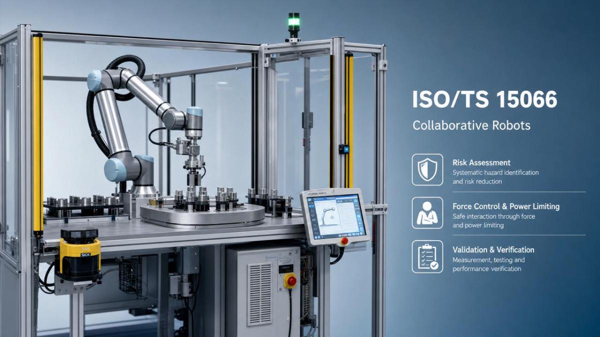
A real cobot cell includes more than an arm. It includes tooling, grippers, parts, fixtures, sensors, software logic, floor layout, operator access, and maintenance routines. The cobot ISO/TS 15066 safety standard matters because it addresses collaborative operation as a system-level issue, not a robot-only label. A 10 kg payload arm moving at reduced speed can still create unacceptable contact risk if the gripper has sharp edges, the part is rigid, or trapping points exist between the robot and a fixed fixture.
In most deployments, risk assessment starts before installation and continues after commissioning. A useful review typically covers at least 4 layers: intended task, foreseeable misuse, contact scenarios, and residual risk after safeguards. This is where many projects fail. Teams assume that a collaborative robot automatically eliminates the need for perimeter controls. In reality, partial guarding, scanner zones, interlocks, and procedural controls may still be necessary in 1 or more stations within the same cell.
The four collaborative operating modes that affect cell design
ISO/TS 15066 is often discussed through four collaborative operation concepts used with industrial robot safety design. Each one influences hardware selection, validation steps, and operator exposure time differently.
- Safety-rated monitored stop: the robot stops when a person enters the collaborative space, and motion resumes only under defined restart conditions.
- Hand guiding: an operator directly guides the robot, usually for teaching or controlled handling tasks.
- Speed and separation monitoring: robot speed changes dynamically based on human distance, often using scanners or vision-based detection.
- Power and force limiting: the robot and end-of-arm tooling are designed so contact remains below acceptable pain or injury thresholds under defined conditions.
Many working cells combine 2 or even 3 of these modes. For example, an operator may load trays under monitored stop, then share space during reduced-speed inspection, while final pick-and-place uses power and force limiting. Quality and safety managers should verify the transition logic between modes, because the risk profile changes within milliseconds when speed limits, detection fields, or stop categories change.
What quality and safety teams should verify first
Before discussing compliance language, review the physical realities of the station. The following checklist helps teams identify where the cobot ISO/TS 15066 safety standard becomes operational rather than theoretical.
The key lesson is simple: the robot arm may be collaborative, but the cell may still not be. Most audit findings arise from tooling, fixtures, access points, or maintenance scenarios rather than from the manipulator itself. A disciplined pre-start review can remove a large share of preventable issues before production ramp-up.
How the Standard Applies to Risk Assessment, Force Limits, and Validation
The practical value of the cobot ISO/TS 15066 safety standard is that it links design intent to measurable acceptance criteria. For quality and safety managers, the central task is not to memorize the document, but to translate it into a repeatable validation plan. That plan normally includes hazard identification, speed and force parameter review, operator interaction mapping, and evidence collection before sign-off.
Risk assessment in a collaborative station
A robust risk assessment should evaluate the full task cycle, not only normal production. Include setup, manual clearing, fault recovery, tool change, cleaning, and preventive maintenance. In many factories, these non-routine tasks account for less than 20% of operating time but a disproportionate share of exposure events. If an operator reaches into the fixture during a jam at 06:00 and the restart sequence is poorly controlled, the collaborative label offers little protection.
Teams should document at least 5 practical questions: where can contact occur, what body region is exposed, what is the expected motion at contact, what secondary hazards exist, and what control reduces severity or probability. Secondary hazards matter. A low-force touch can still lead to injury if the person recoils into a conveyor edge, slips on coolant, or gets trapped between a moving arm and a pallet stop.
Common variables that change the result
- Tool mass and inertia, especially after adding dual grippers or inspection heads
- Part geometry, including burrs, corners, and compressibility
- Robot TCP speed, joint speed, and deceleration settings
- Shared workspace duration, such as 5 seconds per cycle versus 45 seconds per cycle
- Operator posture, line height, and reach direction during load or inspection tasks
Force and pressure limits are not plug-and-play values
One of the most misunderstood parts of collaborative safety is the idea that a supplier can provide a universal speed setting that guarantees compliance. In reality, contact limits depend on body region, contact type, contact area, tooling shape, and dynamic behavior. A rounded compliant gripper pad and a rigid metal bracket can produce very different outcomes even at the same speed and payload.
This is why validation often includes force or pressure measurement under representative conditions. In a mature deployment, testing is not limited to one point. Teams may evaluate multiple contact locations, more than 1 approach direction, and both expected and reasonably foreseeable misuse conditions. If the station changes from a 2 kg carton to a 6 kg machined part, earlier acceptance data may no longer be sufficient.
The table below shows how practical validation factors influence acceptable settings and documentation depth in a real cell.
For quality documentation, the takeaway is that safety settings should be traceable to actual test conditions. A spreadsheet of limits without test context is weak evidence. A documented record linking tool design, payload state, speed zone, and measurement condition is much more defensible during internal review or customer audit.
What Daily Operation, Maintenance, and Change Control Look Like Under the Standard
Even a well-designed cell can drift out of safe collaborative operation over time. The cobot ISO/TS 15066 safety standard has real meaning only when settings, hardware, and procedures remain controlled after handover. In many facilities, risk increases 3 to 6 months after launch, when throughput pressure drives speed changes, tooling is revised, or temporary fixes become permanent.
Operational controls that should not be optional
A practical control plan should cover startup checks, operator training, fault response, and periodic verification. For medium-volume production, a short daily checklist and a deeper weekly review are often more effective than a thick annual binder that nobody uses. Safety performance depends on routine discipline.
- Verify scanner or sensing zones at shift start, including obstruction and fault indication.
- Confirm end-effector condition, especially pads, covers, fasteners, and vacuum retention behavior.
- Review stop and restart function at defined intervals, such as every 7 days or after software changes.
- Check whether speed, payload, or path settings were altered during troubleshooting.
- Record near misses, nuisance stops, and operator bypass attempts as leading indicators.
These checks are especially important in mixed operations where one cell handles multiple SKUs. A line that runs 3 part families with different dimensions may need separate validated recipes. If recipe management is loose, operators can unknowingly run a larger or sharper part under parameters approved for a smaller and safer load.
Change control is where many collaborative cells lose compliance integrity
Most quality and safety managers already control process deviations, but collaborative cells require tighter links between engineering changes and safety review. A new gripper finger, a camera bracket, or a cycle-time optimization that cuts 1.2 seconds may seem minor. Yet each change can alter contact geometry, inertial loading, stopping behavior, or the time a person shares the workspace.
A workable rule is to trigger review whenever one of 6 factors changes: payload, tool geometry, motion path, speed, sensing layout, or operator task sequence. Not every change requires full revalidation, but each one should be screened. If the answer to any screening question is uncertain, escalate to engineering and safety before release to production.
A practical decision path for managers
When evaluating whether a collaborative cell still aligns with the cobot ISO/TS 15066 safety standard, use a simple three-level approach. Level 1 covers no-change verification, such as routine checks and identical replacement parts. Level 2 covers limited review, such as a sensor adjustment or approved recipe update. Level 3 covers formal reassessment, such as a new tool, heavier payload, or modified operator access point. This structure reduces unnecessary downtime while preserving traceability.
Procurement and Integration Questions That Matter More Than Marketing Claims
For buyers and project leaders, one of the biggest mistakes is purchasing a cobot system on the assumption that safety responsibility is fully transferred to the robot vendor. In reality, the final application determines the safety case. Integrators, tooling suppliers, and end users all influence whether the installed cell can satisfy operational expectations. This is why procurement should focus on validation capability, not just robot payload and reach.
Questions to ask before approving a supplier or integrator
- How is the application-specific risk assessment documented, updated, and handed over?
- Which collaborative operating mode or combination of modes is used, and why?
- What evidence supports selected speed, force, and separation settings?
- How are maintenance, fault recovery, and manual intervention addressed?
- What changes would trigger partial or full revalidation after installation?
A credible supplier should answer these questions with engineering logic and test methodology, not broad claims. If documentation stops at product brochures and generic declarations, the project risk remains with the end user. For regulated or high-consequence production environments, that gap can delay internal approval, customer qualification, or insurance review.
What good deliverables should include
At minimum, a solid handover package should include the risk assessment record, safety function description, validated operating parameters, maintenance instructions, training scope, and a clear list of assumptions. If the system was accepted with a maximum part mass of 4 kg, a scanner zone of a given shape, and a restricted manual recovery method, those assumptions should be visible and controlled. Hidden assumptions create audit failures and operational confusion.
In real manufacturing, the cobot ISO/TS 15066 safety standard is valuable because it turns collaboration from a marketing concept into an engineering discipline. It helps quality managers verify that the cell performs as intended, and it helps safety managers prove that hazards were identified, reduced, and monitored with discipline. The standard does not remove the need for judgment; it improves the quality of that judgment with clearer structure, measurable limits, and traceable decisions.
For organizations comparing cobot solutions, retrofitting existing stations, or reviewing change control in a live cell, the most reliable path is data-first evaluation: task mapping, risk review, validation evidence, and documented operational controls. If you need a more defensible framework for supplier qualification, cell assessment, or collaborative safety implementation, contact TSV to discuss your application, request a tailored review checklist, or explore deeper hard-tech benchmarking support.
Search News
Hot Articles
- Carbon Fiber StructuresHow to Specify Aerospace Carbon Fiber Assemblies for Lightweight, Load-Bearing PartsJul 11, 2026
- Machine VisionXiaomi, Alibaba DAMO Academy Drive Open-Source Robotics Model Ecosystem, Lowering Algorithm Development Barriers for Overseas SMEs Adopting Chinese Robotics SolutionsMar 30, 2026
- Cobots & ArmsShanxi 'AI+' Conference Showcases Embodied Intelligence with Multinational Buyer Engagement: Key Industry ImplicationsMar 30, 2026
Popular Tags
Recommended News
 Jul 11, 2026How to Specify Aerospace Carbon Fiber Assemblies for Lightweight, Load-Bearing PartsAerospace carbon fiber assemblies: learn how to specify laminate design, load data, joining methods, and inspection controls for lighter, reliable load-bearing aerospace parts.Elena Rostova (UAV Systems Researcher)
 Mar 30, 2026Xiaomi, Alibaba DAMO Academy Drive Open-Source Robotics Model Ecosystem, Lowering Algorithm Development Barriers for Overseas SMEs Adopting Chinese Robotics SolutionsXiaomi & Alibaba DAMO Academy's open-source robotics models lower algorithm barriers for global SMEs. Boost efficiency in manufacturing, logistics & smart retail with ROS 2 compatible solutions.TSV Data Lab
 Mar 30, 2026Shanxi 'AI+' Conference Showcases Embodied Intelligence with Multinational Buyer Engagement: Key Industry ImplicationsShanxi 'AI+' Conference highlights embodied intelligence with Tesla, Ubtech & Jiantao showcasing multimodal robotics. 40+ global buyers validated tech on-site, creating new B2B channels for industrial automation & AI solutions.Chen Wei (Automation Lead Engineer)
 Mar 30, 2026Zhongguancun Unveils 6G Integrated Sensing-Computing-Intelligence Platform to Empower Embodied Robots for Global Industrial ApplicationsZhongguancun's new 6G platform revolutionizes industrial robotics with <10ms latency, empowering global automotive, logistics & port automation. Discover how this tech boosts China's smart manufacturing exports.TSV Data Lab
 Mar 30, 2026Mech-Mind Tianjin Embodied Intelligence R&D and Production Base Goes Live, Cutting Delivery Time by 20%–30% for Global Customized AMR+Vision SolutionsMech-Mind's Tianjin AMR+Vision production base cuts delivery time by 20%-30% for欧美 & Latin American markets. Discover how this PLd-certified facility accelerates customized robotics solutions for smart manufacturing and logistics.Chen Wei (Automation Lead Engineer)
 Mar 30, 2026Boao Forum Reveals 'Co-evolution of Big and Small Brains' Trend in Humanoid Robots, China's Embodied Intelligence Accelerates Adaptation to Overseas Manufacturing Service ScenariosDiscover how China's humanoid robots, featuring 'Co-evolution of Big and Small Brains,' are revolutionizing global manufacturing. Learn about Embodied Tian Gong 3.0's ISO compliance and overseas deployment at Boao Forum 2026.Chen Wei (Automation Lead Engineer)
 Mar 30, 2026China Railway Industrial Secures Patent for Embodied Robotics in Material Handling, Boosting High-Precision Delivery Capabilities for Overseas Infrastructure and Manufacturing ProjectsChina Railway Industrial's new patent for embodied robotics in material handling boosts high-precision delivery for global infrastructure & manufacturing. Discover how this innovation enhances logistics accuracy in automotive, rail transit & EPC projects.Chen Wei (Automation Lead Engineer)
 Sep 28, 2026Spindle Runout Measurement in Germany: DIN Standards, Methods, and Acceptance LimitsSpindle runout measurement Germany: explore DIN standards, proven methods, acceptance limits, and audit-ready practices for reliable machining quality.Dr. Marcus Vance
 Sep 27, 2026How to Select Wall-Mount Edge Devices for Space-Constrained Factory NetworksWall mount edge devices for space-constrained factories: evaluate workload, thermal design, power resilience, cable access, and network reliability for smarter deployments.TSV Data Lab
 Sep 26, 2026Machining Tolerance Analysis: How to Set Limits That Meet Function and Cost TargetsMachining tolerance analysis: learn how to set functional limits, control tolerance stacks, reduce inspection risk, and balance precision with production cost.Dr. Marcus Vance
 Sep 25, 2026How to Evaluate an Industrial Infrastructure Data Platform for Multi-Site OperationsIndustrial infrastructure data platform evaluation guide for multi-site operations: compare data quality, edge resilience, interoperability, governance, and scalable proof-of-value criteria.Victor Lin (Chief Software Architect)
 Sep 24, 2026How to Select Machine Vision Optics for Accurate Inspection at Different Working DistancesMachine vision optics selection guide for accurate inspection at every working distance. Compare FOV, pixel scale, DOF, distortion, lighting, and telecentric options.TSV Data Lab
 Sep 23, 2026How to Evaluate a Machine Vision System Integrator for High-Speed Inspection LinesChoose a machine vision system integrator with proven expertise in high-speed inspection, reliable reject timing, robust optics, and measurable acceptance criteria.TSV Data Lab
 Sep 28, 2026When is a SCADA API the right choice for connecting plant systems?SCADA API guide: learn when governed plant data integration improves traceability, security, and scalability—without compromising real-time control.Victor Lin (Chief Software Architect)
 Sep 27, 2026How SCADA data integration improves traceability across production linesSCADA data integration connects production-line data to improve traceability, accelerate quality investigations, and strengthen safety decisions.Victor Lin (Chief Software Architect)
 Sep 26, 2026What to define before starting SCADA integration planningSCADA integration planning starts with clear scope, control boundaries, data models, cybersecurity, and testing. Discover the definitions that reduce risk and costly rework.Victor Lin (Chief Software Architect)
 Sep 25, 2026How a smart factory with Industrial IoT reduces production blind spotsDiscover how a smart factory with Industrial IoT turns real-time machine, quality, and workflow data into actionable insights that reduce production blind spots and delivery risks.Victor Lin (Chief Software Architect)
 Sep 24, 2026When does Industrial IoT make smart manufacturing easier to scale?Smart manufacturing Industrial IoT scales when trusted data, interoperable systems, and secure workflows turn connected assets into measurable gains.TSV Data Lab
 Sep 23, 2026What drives ultra-precision machining cost at 1-micron tolerance?Ultra precision machining cost per part at 1 micron tolerance depends on process, material, metrology, and yield. Learn how to compare quotes confidently.Dr. Marcus Vance
 Sep 22, 2026Drone Engine-T550CC Applications: Build the UAV Power System Around the MissionAn application guide for Drone Engine-T550CC integration, covering payload planning, airframe matching, cooling, fuel, vibration, test procedures, documentation, and service preparation.Elena Rostova (UAV Systems Researcher)
 Sep 22, 2026How to Evaluate Industrial Edge Computing Vendors for Factory DeploymentIndustrial edge computing vendor evaluation guide for factories: compare latency, protocol fit, reliability, security, and lifecycle support before deployment.TSV Data Lab
 Sep 21, 2026Drone Payload Integration: Matching Power, Data, and Center of Gravity for Reliable FlightsDrone payload integration made practical: balance power, data, center of gravity, and endurance to build safer, more reliable mission-ready flights.Elena Rostova (UAV Systems Researcher)
 Sep 20, 2026Autonomous Navigation Pricing: Cost Drivers and Budget Benchmarks for AMR ProjectsAutonomous navigation price explained: compare AMR cost drivers, software, sensors, integration, safety, and lifecycle budgets to build a scalable project plan.Chen Wei (Automation Lead Engineer)
 Sep 19, 2026How to Scope Automation Integration Services for Multi-System Factory ProjectsAutomation integration services: learn how to scope multi-system factory projects with clear workflows, interface contracts, safety boundaries, and acceptance criteria.Victor Lin (Chief Software Architect)























