Drone Payload Integration: Matching Power, Data, and Center of Gravity for Reliable Flights
Publication Date
author
A payload can be electrically compatible with a drone, fit its mounting pattern, and remain within the published payload mass limit, yet still produce unreliable flights. The reason is that drone payload integration is a system problem. Power draw changes battery behavior; data traffic competes with command links; wiring alters electromagnetic conditions; and a small offset in mass can force the flight controller to work harder through every maneuver.
The practical question is not “Can this airframe lift the payload?” It is “Can the complete aircraft carry, power, communicate with, stabilize, and safely recover this payload through the intended mission profile?” A sound answer requires a combined review of electrical margins, data interfaces, mechanical loads, center of gravity, thermal behavior, and flight-control response.
Start with the mission configuration, not the payload datasheet
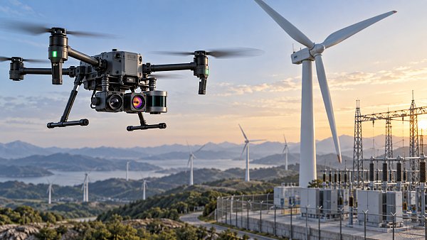
Payload specifications are usually measured under controlled conditions. An EO/IR camera may list nominal voltage and peak current; a LiDAR unit may state its data output; a gimbal may specify its mass and operating range. None of those values alone describes the installed aircraft.
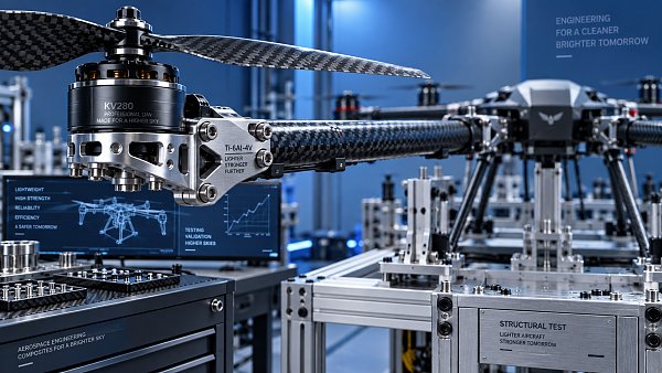
Build the evaluation around the heaviest and most demanding mission configuration. Include the payload, gimbal or mount, cabling, fasteners, vibration isolators, protective housings, external antennas, storage devices, and any onboard compute module. A compact sensor often becomes a substantially larger integration load after these supporting components are added.
The mission profile matters just as much. A short hover inspection, a mapping flight with repeated turns, an agricultural route near dust and spray, and a long-range transit operation put different demands on the same aircraft. A payload arrangement that is acceptable during a stationary hover may become unstable during acceleration, descent, crosswind operation, or return-to-home behavior.
Power compatibility is a budget with operating margins
Power integration should begin at the aircraft power-distribution level, rather than at the connector. Matching a payload’s stated voltage to an available output is necessary, but it does not establish that the installation is safe or reliable.
Review continuous demand, startup demand, transient demand, and behavior during low-battery conditions. Cameras with heaters, active sensors, radios, gimbals, illumination modules, and edge computers can draw brief but significant current peaks. If the supply voltage sags during one of those peaks, the result may be a payload reboot, corrupted recording, a gimbal reset, or interference with other aircraft electronics.
The airframe’s propulsion system also competes for the same stored energy. A payload may consume a modest share of battery capacity at cruise, while the motors require much more current during takeoff, braking, wind compensation, or an emergency maneuver. Assess the whole current profile instead of treating payload consumption as an isolated number.
Use an appropriate margin between expected load and the power path’s usable capability. The exact margin depends on the airframe, battery architecture, ambient temperature, and criticality of the payload, but the principle is consistent: do not design around nominal consumption alone. A power budget should identify each load, its operating state, its expected duration, and whether it can switch on simultaneously with another load.
Connector selection deserves the same discipline. A connector may physically mate while still being unsuitable for vibration, repeated field servicing, current level, or shielding needs. Strain relief is not cosmetic. Unsupported cable mass can fatigue conductors, loosen connectors, and transfer vibration directly into a sensor or gimbal.
Data interfaces must preserve timing, not merely transfer files
Drone payload integration frequently fails at the data layer because “compatible interface” is treated as a complete answer. A payload may provide Ethernet, serial, USB, CAN, PWM, or another interface, while the aircraft offers one or more of the same ports. The remaining questions are more important: which device is the controller, what protocol is used, what messages are required, and what happens when timing changes?
Separate the data paths by function. Flight-critical command and telemetry paths require predictable behavior. High-volume sensor output may require much more bandwidth but can often tolerate controlled buffering. Video, point clouds, image capture triggers, gimbal commands, GNSS data, and health reporting should not be assumed to coexist cleanly on a shared link without a traffic and timing plan.
For mapping and inspection missions, the relationship between sensor capture time and aircraft position can be more valuable than raw bandwidth. A high-resolution image or LiDAR frame is of limited use if its timestamp cannot be consistently aligned with GNSS and inertial data. Measure or characterize the full chain: trigger signal, sensor exposure or scan timing, payload processing, transport delay, onboard logging, and metadata generation.
Data storage is also part of the architecture. Streaming all mission data to the ground can be impractical where radio capacity changes with range, terrain, antenna orientation, or electromagnetic congestion. Local recording protects mission data, but it introduces separate requirements for write speed, power-loss handling, file integrity, storage capacity, and retrieval workflow. The right arrangement often uses a reliable onboard record as the primary dataset and a lower-rate downlink for monitoring.
Electromagnetic compatibility is an installation issue
A payload can meet its own electromagnetic requirements and still interfere with the aircraft after installation. Brushless motors, electronic speed controllers, switching regulators, radios, video transmitters, high-speed digital cables, and active sensors all create possible coupling paths. The issue is not simply whether interference exists; it is whether it reaches a receiver, compass, GNSS antenna, control link, or sensitive sensor at a level that affects the mission.
Physical layout is often the first control. Keep GNSS antennas and magnetometers away from high-current paths, transmitters, and noisy power converters. Route power and data cables deliberately; avoid unnecessary loops, poorly supported bundles, and unshielded high-speed runs placed beside sensitive navigation wiring. Where shielding is required, its termination and grounding approach must match the system architecture. A shield connected without a clear return-path strategy may not solve the intended problem.
Do not rely only on a bench test with motors stopped. Evaluate communications, navigation quality, payload output, and video or data links with propulsion operating and with the payload in its normal duty cycle. Testing should include the power states and radio states that the mission will actually use, including transmitter activity, gimbal movement, sensor illumination, and onboard computing load.
Center of gravity is more than a balance-point check
Aircraft balance is usually discussed as a center-of-gravity, or CG, limit. That limit matters, but payload placement also changes moments of inertia and aerodynamic exposure. A mass mounted far from the vehicle’s original CG may be within the total payload rating while still making pitch, roll, or yaw control less responsive. A large sensor housing can also add drag or catch crosswinds, creating a disturbance that is not visible in a static weight calculation.
Determine the installed CG from measured component masses and their locations relative to the airframe reference axes. Account for configuration changes: removable batteries, interchangeable lenses, different liquid volumes, protective covers, and deployable equipment can shift the result. A package that is centered in one configuration may become forward-heavy or side-heavy after a battery swap or field modification.
Vertical location matters as well. Payload mass hanging substantially below the rotor plane can change pendulum-like behavior and increase the influence of mount flexibility. A top-mounted payload may preserve ground clearance but alter rollover behavior during landing and expose the aircraft to greater wind moments. There is no universal best location; the preferred arrangement depends on the flight-control authority, landing gear geometry, sensor field of view, and expected operating environment.
Mount stiffness and vibration isolation must be treated together
A rigid mount protects alignment, but it can pass motor and propeller vibration directly to cameras, inertial sensors, or scanning instruments. An overly soft isolator reduces transmitted vibration but permits unwanted movement, slow settling, or resonant oscillation. The correct design has enough stiffness to retain pointing accuracy and enough damping to control the frequency range that matters to the payload.
Mounting hardware should be assessed for more than static strength. Inspect fastener retention, local frame reinforcement, load paths during hard landings, cable clearance through the full gimbal range, and access for inspection. A payload mount that obscures cooling openings, service latches, battery removal, or emergency disconnects can turn ordinary maintenance into an operational risk.
Flight endurance must be validated with usable reserve
Payload mass reduces endurance through more than the weight itself. The aircraft may need higher rotor thrust to hover, more energy to climb, and more control effort in wind. Payload power consumption reduces the energy available for propulsion. Additional drag, especially from external cameras, housings, antennas, or delivery modules, can further change cruise efficiency.
A practical endurance estimate should be based on the complete, mission-ready aircraft. It should include takeoff, transit, station keeping or collection time, return, and an operational reserve appropriate to the planned flight. Avoid treating an advertised no-payload endurance figure as a mission commitment. The useful result is not the longest possible airborne time; it is the time available for the assigned task while retaining controllability and recovery margin.
Thermal effects belong in this assessment. A payload that operates normally on the ground may heat its enclosure or power converter during an extended flight, especially when airflow is restricted by a mounting plate or protective housing. Battery behavior, processor throttling, sensor calibration, and image noise can all change as temperatures move away from benign bench conditions.
A disciplined integration sequence reduces late-stage surprises
The most effective review order follows the dependencies between subsystems. Select the mission payload only after defining what data must be captured, at what accuracy, over what duration, and under what conditions. Then evaluate the aircraft configuration as an integrated assembly.
- Define the mission output. Specify the required imagery, point cloud, measurement, delivery action, or other mission result, including timing and quality needs.
- Create an installed mass model. Include all brackets, cables, adapters, compute hardware, and accessories, then calculate CG for each permitted configuration.
- Create a power-state table. Identify voltage range, continuous and peak load, startup behavior, thermal load, and the consequence of a payload power fault.
- Map every interface. Document physical connectors, protocols, command ownership, data direction, rates, timestamps, and failure recovery behavior.
- Review physical and electromagnetic layout. Confirm cable routing, antenna separation, cooling, vibration isolation, service access, and moving-clearance envelopes.
- Test progressively. Begin with powered bench checks, then restrained propulsion checks, hover checks, and controlled mission-like flights before approving a repeatable configuration.
Configuration control is essential once the system passes validation. A replacement cable, alternative battery, different mounting screw, firmware change, or revised sensor setting can alter a previously acceptable result. Keep a configuration record that identifies the approved payload version, mount, cable set, firmware combination, CG condition, and test status. This is especially valuable when several payloads share one airframe.
Common decisions that create avoidable risk
The most common error is using maximum payload capacity as the selection criterion. That figure is a boundary, not evidence that the aircraft will meet endurance, stability, thermal, or data-quality requirements in a real mission.
Another weak approach is validating components independently and assuming that passing results add up to a passing system. A camera can record correctly, a gimbal can stabilize correctly, and a drone can fly correctly in separate tests while their combined wiring, current demand, vibration, and timing produce poor mission data.
It is also risky to solve a CG issue with improvised counterweights before reviewing placement options. Counterweight can restore the balance point, but it consumes payload capacity and endurance without producing mission value. Relocating a battery, compute module, or mounting interface is often a better engineering answer when the airframe permits it.
For procurement and design reviews, require measurable interface information rather than broad compatibility claims: installed mass, CG envelope, voltage range, current profile, connector and pinout details, data protocol, bandwidth expectations, timing method, environmental constraints, mounting geometry, and payload fault behavior. This parameter-first approach reflects the engineering principle used by TechStat Vanguard: claims are useful only when they can be traced to conditions, limits, and repeatable system behavior.
Reliable flights emerge when power, data, mechanics, and control are evaluated as one configuration. The final approval should be based on mission-ready behavior, not on a collection of compatible datasheets.
Search News
Hot Articles
- Carbon Fiber StructuresHow to Specify Aerospace Carbon Fiber Assemblies for Lightweight, Load-Bearing PartsJul 11, 2026
- Machine VisionXiaomi, Alibaba DAMO Academy Drive Open-Source Robotics Model Ecosystem, Lowering Algorithm Development Barriers for Overseas SMEs Adopting Chinese Robotics SolutionsMar 30, 2026
- Cobots & ArmsShanxi 'AI+' Conference Showcases Embodied Intelligence with Multinational Buyer Engagement: Key Industry ImplicationsMar 30, 2026
Popular Tags
Recommended News
 Jul 11, 2026How to Specify Aerospace Carbon Fiber Assemblies for Lightweight, Load-Bearing PartsAerospace carbon fiber assemblies: learn how to specify laminate design, load data, joining methods, and inspection controls for lighter, reliable load-bearing aerospace parts.Elena Rostova (UAV Systems Researcher)
 Mar 30, 2026Xiaomi, Alibaba DAMO Academy Drive Open-Source Robotics Model Ecosystem, Lowering Algorithm Development Barriers for Overseas SMEs Adopting Chinese Robotics SolutionsXiaomi & Alibaba DAMO Academy's open-source robotics models lower algorithm barriers for global SMEs. Boost efficiency in manufacturing, logistics & smart retail with ROS 2 compatible solutions.TSV Data Lab
 Mar 30, 2026Shanxi 'AI+' Conference Showcases Embodied Intelligence with Multinational Buyer Engagement: Key Industry ImplicationsShanxi 'AI+' Conference highlights embodied intelligence with Tesla, Ubtech & Jiantao showcasing multimodal robotics. 40+ global buyers validated tech on-site, creating new B2B channels for industrial automation & AI solutions.Chen Wei (Automation Lead Engineer)
 Mar 30, 2026Zhongguancun Unveils 6G Integrated Sensing-Computing-Intelligence Platform to Empower Embodied Robots for Global Industrial ApplicationsZhongguancun's new 6G platform revolutionizes industrial robotics with <10ms latency, empowering global automotive, logistics & port automation. Discover how this tech boosts China's smart manufacturing exports.TSV Data Lab
 Mar 30, 2026Mech-Mind Tianjin Embodied Intelligence R&D and Production Base Goes Live, Cutting Delivery Time by 20%–30% for Global Customized AMR+Vision SolutionsMech-Mind's Tianjin AMR+Vision production base cuts delivery time by 20%-30% for欧美 & Latin American markets. Discover how this PLd-certified facility accelerates customized robotics solutions for smart manufacturing and logistics.Chen Wei (Automation Lead Engineer)
 Mar 30, 2026Boao Forum Reveals 'Co-evolution of Big and Small Brains' Trend in Humanoid Robots, China's Embodied Intelligence Accelerates Adaptation to Overseas Manufacturing Service ScenariosDiscover how China's humanoid robots, featuring 'Co-evolution of Big and Small Brains,' are revolutionizing global manufacturing. Learn about Embodied Tian Gong 3.0's ISO compliance and overseas deployment at Boao Forum 2026.Chen Wei (Automation Lead Engineer)
 Mar 30, 2026China Railway Industrial Secures Patent for Embodied Robotics in Material Handling, Boosting High-Precision Delivery Capabilities for Overseas Infrastructure and Manufacturing ProjectsChina Railway Industrial's new patent for embodied robotics in material handling boosts high-precision delivery for global infrastructure & manufacturing. Discover how this innovation enhances logistics accuracy in automotive, rail transit & EPC projects.Chen Wei (Automation Lead Engineer)
 Sep 21, 2026Drone Payload Integration: Matching Power, Data, and Center of Gravity for Reliable FlightsDrone payload integration made practical: balance power, data, center of gravity, and endurance to build safer, more reliable mission-ready flights.Elena Rostova (UAV Systems Researcher)
 Sep 20, 2026Autonomous Navigation Pricing: Cost Drivers and Budget Benchmarks for AMR ProjectsAutonomous navigation price explained: compare AMR cost drivers, software, sensors, integration, safety, and lifecycle budgets to build a scalable project plan.Chen Wei (Automation Lead Engineer)
 Sep 19, 2026How to Scope Automation Integration Services for Multi-System Factory ProjectsAutomation integration services: learn how to scope multi-system factory projects with clear workflows, interface contracts, safety boundaries, and acceptance criteria.Victor Lin (Chief Software Architect)
 Sep 18, 2026Selecting UAV Aerospace Structural Parts for Strength, Weight, and Fatigue LifeUAV aerospace structural parts guide: compare strength, weight, stiffness, fatigue life, joints, and traceability to select reliable flight-ready components.Elena Rostova (UAV Systems Researcher)
 Sep 17, 2026Selecting Commercial Drone Payloads for European Inspection ProjectsCommercial drone payloads Europe: learn how to select RGB, thermal and LiDAR systems for compliant, reliable inspection data and better project outcomes.Elena Rostova (UAV Systems Researcher)
 Sep 16, 2026Machining Tolerance Validation: How to Verify Critical Dimensions Before Production ReleaseMachining tolerance analysis validation: verify critical dimensions, measurement systems, process capability, and tolerance stacks before production release.Dr. Marcus Vance
 Sep 15, 2026AGV Tape Guidance vs Laser Navigation: Which Fits Your Warehouse Layout?AGV tape guidance comparison: discover how tape and laser navigation fit changing warehouse layouts, docking needs, floor conditions, maintenance, and route flexibility.Chen Wei (Automation Lead Engineer)
 Sep 14, 2026How Point Cloud Analytics Improves Asset Inspection Workflows Across GCC ProjectsPoint cloud analytics GCC helps project leaders improve asset inspections with accurate change detection, safer workflows, and faster maintenance decisions.TSV Data Lab
 Sep 13, 2026How Aerospace Manufacturers Can Build a Digital Thread From Design to Certified ProductionDigital manufacturing for aerospace: learn how to build a traceable digital thread from design through certified production, supplier control, and audit-ready compliance.Victor Lin (Chief Software Architect)
 Sep 12, 2026How to Select a Thermal Sensor for Mapping Drones in Surveying ProjectsMapping drone thermal sensor selection made simple: compare GSD, radiometric data, NETD, calibration, and workflow fit for accurate, survey-ready thermal maps.Elena Rostova (UAV Systems Researcher)
 Sep 11, 2026Integrating Photogrammetry Workflows into Digital Twin Projects Without Data BottlenecksPhotogrammetry workflow integration for digital twins: learn how to streamline capture, validation, versioning, and delivery to prevent data bottlenecks.Victor Lin (Chief Software Architect)
 Sep 10, 2026Hard-Tech Supply Chain Procurement: Qualifying Suppliers to Cut Lead-Time RiskHard-tech supply chain procurement guide: qualify suppliers with proven process, traceability, capacity, and change control to reduce lead-time risk.Chen Wei (Automation Lead Engineer)
 Sep 09, 2026Industrial Application Notes: Cost Factors That Shape Automation Project BudgetsIndustrial application notes cost factors explained: uncover the engineering, safety, integration, and commissioning variables that shape accurate automation budgets.Victor Lin (Chief Software Architect)
 Sep 08, 2026Supplier Discovery for Sourcing: How Buyers Can Verify Capability and Supply RiskSupplier discovery for sourcing: learn how to verify supplier capability, traceability, quote assumptions, and supply risk before placing production orders.TSV Data Lab
 Sep 07, 2026What Determines Process Control Systems Pricing? A Buyer’s Cost GuideProcess control systems pricing explained: compare hardware, engineering, integration, cybersecurity, validation, and lifecycle costs to choose the right-value solution.Victor Lin (Chief Software Architect)
 Sep 07, 2026AMR Robots in ASEAN: Which Industries Are Adopting Them—and Why?AMR robots ASEAN adoption is accelerating in electronics, automotive, warehousing, healthcare, and cold chain. Explore use cases, risks, and deployment insights.Chen Wei (Automation Lead Engineer)
 Sep 05, 2026How to Evaluate Supplier Qualification Support Tools for Industrial Procurement TeamsSupplier qualification support tools help industrial procurement teams verify technical evidence, manage risk, and make defensible supplier approvals. Learn what to evaluate.Victor Lin (Chief Software Architect)