Carbon Fiber Frame Components: Common Types, Load Limits, and Design Trade-Offs
Publication Date
author
Why do carbon fiber frame components attract so much attention?
Carbon fiber frame components are often introduced through weight reduction, but that is only the visible part of the story.
In practice, designers care more about stiffness direction, fatigue resistance, joint behavior, and how a frame survives repeated load cycles.
That is why the topic matters across robotics, UAV structures, industrial equipment, and precision platforms.
A lighter frame can improve payload margin, motion efficiency, and transport handling, but only if the structural logic is correct.
More commonly, the real decision starts with a simple question: where will the load actually travel?
TechStat Vanguard consistently emphasizes this engineering-first view. Parameters matter more than broad claims, especially in hard-tech sourcing.
So when evaluating carbon fiber frame components, the useful comparison is not “lighter versus heavier.” It is “lighter under which load case, with what safety margin, and for how long?”
Which carbon fiber frame components are most common in real assemblies?
The phrase covers more than one part type. Different components serve different structural jobs.
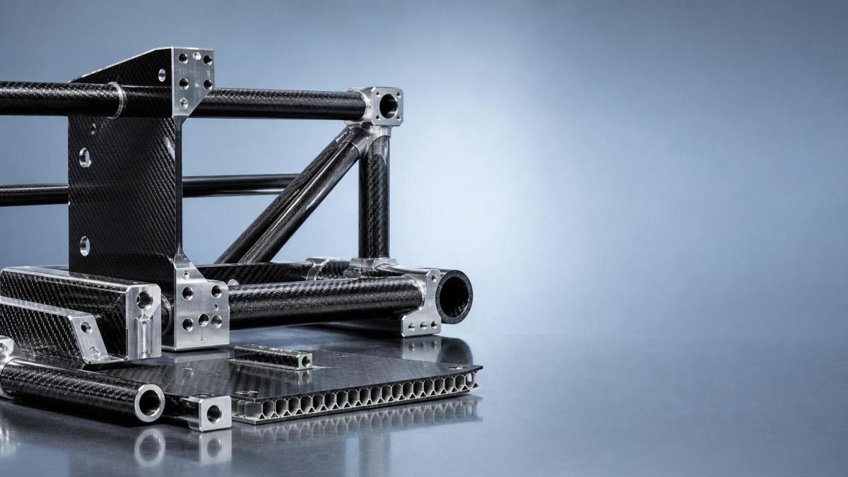
In most assemblies, common carbon fiber frame components include:
- Tubular members for trusses, booms, and long-span supports
- Flat panels for skins, covers, and shear-carrying surfaces
- Sandwich panels for high bending stiffness at low mass
- Brackets and gussets for localized reinforcement
- Arms and struts used in UAV, automation, and sensor frames
- Hybrid joints with aluminum, titanium, or steel inserts
Tubular parts work well when axial stiffness is critical. Panels become more useful when the design needs broad surface support.
Sandwich construction is popular because it offers strong bending performance without relying on thick solid laminate.
However, every form changes how loads are introduced. A tube that performs well in tension may struggle at a drilled joint.
That is why carbon fiber frame components should be reviewed as a system, not as isolated catalog items.
How should load limits be understood without falling for oversimplified numbers?
This is where many comparisons become misleading. Carbon fiber does not have one universal load limit.
The practical limit depends on fiber orientation, resin system, wall thickness, joint geometry, environmental exposure, and the type of force involved.
A component may show excellent tensile strength along the fiber direction but much lower tolerance in through-thickness loading.
Compression is another caution area. Slender members may fail by buckling before the laminate reaches its material limit.
In repeated service, fatigue can reduce confidence long before static strength is fully used.
A more reliable way to judge carbon fiber frame components is to match each part with its dominant load case:
If a datasheet presents one headline strength value, that value is only a starting point. It is not the operating truth.
TSV-style evaluation focuses on test conditions, safety factors, and failure mode clarity, because those details shape real structural confidence.
Where do the biggest design trade-offs usually appear?
Most carbon fiber frame components involve compromise. Strong performance in one area can create cost or process pressure somewhere else.
One common trade-off is stiffness versus damage tolerance. Very stiff laminates may react poorly to impact or localized edge loading.
Another is weight versus manufacturability. Thin walls save mass, yet they can become harder to machine, inspect, and assemble consistently.
There is also a recurring choice between bonded joints and bolted joints.
- Bonded joints spread load well, but surface preparation and cure control become critical.
- Bolted joints are easier to service, but they introduce holes, bearing stress, and local weakening.
- Hybrid joints often balance both, though they add process complexity.
Cost also deserves a more precise view. Material price is only one layer.
Tooling, cure cycle, scrap rate, inspection effort, and rework risk can outweigh raw material savings.
For that reason, the best carbon fiber frame components are not always the lightest ones. They are the ones that maintain tolerances and survive the service environment predictably.
What mistakes show up when carbon fiber frame components move from concept to application?
The most frequent mistake is treating composite behavior like metal behavior. The same geometry does not always transfer safely.
Another issue is underestimating joints. Many failures begin near interfaces, not in the middle of the laminate.
In actual field use, several warning signs deserve attention:
- Visible cracking around holes or inserts
- Unexpected vibration growth after repeated cycles
- Bond line separation after thermal changes
- Dimensional drift affecting alignment or sensor accuracy
- Local crush marks from clamping or over-torque
Impact damage is especially tricky because it may be hard to detect from the surface.
That is why inspection planning matters almost as much as material selection.
When information is vague, a practical response is to ask for fatigue data, coupon test methods, insert design details, and dimensional inspection records.
This data-driven approach aligns with the broader hard-tech logic promoted by TechStat Vanguard: remove language inflation, then verify the numbers that actually control field performance.
How do you compare options without getting lost in marketing claims?
A useful comparison starts with the operating profile, not the brochure headline.
If the frame sees high vibration, fatigue evidence matters more than peak static strength. If it carries optics, stiffness stability and thermal behavior may dominate.
If the structure is assembled repeatedly, serviceability and insert durability become more important.
The following checklist helps narrow the decision:
- Define the main load path: tension, bending, torsion, compression, or mixed loading
- Confirm whether failure risk comes from laminate, core, or joint region
- Review fatigue cycles, impact exposure, and temperature range
- Check tolerance retention after machining and assembly
- Compare inspection methods and repair practicality
- Balance mass savings against lead time and repeatability
This kind of screening makes carbon fiber frame components easier to judge across aerospace-adjacent, automation, and sensor-support applications.
It also reduces the chance of selecting a technically impressive part that creates avoidable integration problems later.
What is the sensible next step if you are still at the evaluation stage?
Start by converting general interest into a measurable requirement set.
List the actual span, expected load cases, allowable deflection, attachment method, thermal conditions, and service life assumptions.
Then compare carbon fiber frame components against those conditions, rather than against broad category claims.
In many cases, the clearest decision comes from a small matrix: component type, joint design, verified load data, fatigue evidence, and manufacturing tolerance.
That approach reflects a larger engineering principle: structure selection should follow evidence, not adjectives.
If you are building a shortlist, prioritize options with transparent test conditions, clear failure criteria, and realistic assembly documentation.
Carbon fiber frame components can deliver major performance benefits, but only when the trade-offs are understood early and checked against real operating demands.
A disciplined review of load limits, joints, fatigue, and process capability usually saves more time than any late-stage redesign.
Search News
Hot Articles
- Carbon Fiber StructuresHow to Specify Aerospace Carbon Fiber Assemblies for Lightweight, Load-Bearing PartsJul 11, 2026
- Machine VisionXiaomi, Alibaba DAMO Academy Drive Open-Source Robotics Model Ecosystem, Lowering Algorithm Development Barriers for Overseas SMEs Adopting Chinese Robotics SolutionsMar 30, 2026
- Cobots & ArmsShanxi 'AI+' Conference Showcases Embodied Intelligence with Multinational Buyer Engagement: Key Industry ImplicationsMar 30, 2026
Popular Tags
Recommended News
 Jul 11, 2026How to Specify Aerospace Carbon Fiber Assemblies for Lightweight, Load-Bearing PartsAerospace carbon fiber assemblies: learn how to specify laminate design, load data, joining methods, and inspection controls for lighter, reliable load-bearing aerospace parts.Elena Rostova (UAV Systems Researcher)
 Mar 30, 2026Xiaomi, Alibaba DAMO Academy Drive Open-Source Robotics Model Ecosystem, Lowering Algorithm Development Barriers for Overseas SMEs Adopting Chinese Robotics SolutionsXiaomi & Alibaba DAMO Academy's open-source robotics models lower algorithm barriers for global SMEs. Boost efficiency in manufacturing, logistics & smart retail with ROS 2 compatible solutions.TSV Data Lab
 Mar 30, 2026Shanxi 'AI+' Conference Showcases Embodied Intelligence with Multinational Buyer Engagement: Key Industry ImplicationsShanxi 'AI+' Conference highlights embodied intelligence with Tesla, Ubtech & Jiantao showcasing multimodal robotics. 40+ global buyers validated tech on-site, creating new B2B channels for industrial automation & AI solutions.Chen Wei (Automation Lead Engineer)
 Mar 30, 2026Zhongguancun Unveils 6G Integrated Sensing-Computing-Intelligence Platform to Empower Embodied Robots for Global Industrial ApplicationsZhongguancun's new 6G platform revolutionizes industrial robotics with <10ms latency, empowering global automotive, logistics & port automation. Discover how this tech boosts China's smart manufacturing exports.TSV Data Lab
 Mar 30, 2026Mech-Mind Tianjin Embodied Intelligence R&D and Production Base Goes Live, Cutting Delivery Time by 20%–30% for Global Customized AMR+Vision SolutionsMech-Mind's Tianjin AMR+Vision production base cuts delivery time by 20%-30% for欧美 & Latin American markets. Discover how this PLd-certified facility accelerates customized robotics solutions for smart manufacturing and logistics.Chen Wei (Automation Lead Engineer)
 Mar 30, 2026Boao Forum Reveals 'Co-evolution of Big and Small Brains' Trend in Humanoid Robots, China's Embodied Intelligence Accelerates Adaptation to Overseas Manufacturing Service ScenariosDiscover how China's humanoid robots, featuring 'Co-evolution of Big and Small Brains,' are revolutionizing global manufacturing. Learn about Embodied Tian Gong 3.0's ISO compliance and overseas deployment at Boao Forum 2026.Chen Wei (Automation Lead Engineer)
 Mar 30, 2026China Railway Industrial Secures Patent for Embodied Robotics in Material Handling, Boosting High-Precision Delivery Capabilities for Overseas Infrastructure and Manufacturing ProjectsChina Railway Industrial's new patent for embodied robotics in material handling boosts high-precision delivery for global infrastructure & manufacturing. Discover how this innovation enhances logistics accuracy in automotive, rail transit & EPC projects.Chen Wei (Automation Lead Engineer)
 Sep 23, 2026How to Evaluate a Machine Vision System Integrator for High-Speed Inspection LinesChoose a machine vision system integrator with proven expertise in high-speed inspection, reliable reject timing, robust optics, and measurable acceptance criteria.TSV Data Lab
 Sep 23, 2026What drives ultra-precision machining cost at 1-micron tolerance?Ultra precision machining cost per part at 1 micron tolerance depends on process, material, metrology, and yield. Learn how to compare quotes confidently.Dr. Marcus Vance
 Sep 22, 2026Drone Engine-T550CC Applications: Build the UAV Power System Around the MissionAn application guide for Drone Engine-T550CC integration, covering payload planning, airframe matching, cooling, fuel, vibration, test procedures, documentation, and service preparation.Elena Rostova (UAV Systems Researcher)
 Sep 22, 2026How to Evaluate Industrial Edge Computing Vendors for Factory DeploymentIndustrial edge computing vendor evaluation guide for factories: compare latency, protocol fit, reliability, security, and lifecycle support before deployment.TSV Data Lab
 Sep 21, 2026Drone Payload Integration: Matching Power, Data, and Center of Gravity for Reliable FlightsDrone payload integration made practical: balance power, data, center of gravity, and endurance to build safer, more reliable mission-ready flights.Elena Rostova (UAV Systems Researcher)
 Sep 20, 2026Autonomous Navigation Pricing: Cost Drivers and Budget Benchmarks for AMR ProjectsAutonomous navigation price explained: compare AMR cost drivers, software, sensors, integration, safety, and lifecycle budgets to build a scalable project plan.Chen Wei (Automation Lead Engineer)
 Sep 19, 2026How to Scope Automation Integration Services for Multi-System Factory ProjectsAutomation integration services: learn how to scope multi-system factory projects with clear workflows, interface contracts, safety boundaries, and acceptance criteria.Victor Lin (Chief Software Architect)
 Sep 18, 2026Selecting UAV Aerospace Structural Parts for Strength, Weight, and Fatigue LifeUAV aerospace structural parts guide: compare strength, weight, stiffness, fatigue life, joints, and traceability to select reliable flight-ready components.Elena Rostova (UAV Systems Researcher)
 Sep 17, 2026Selecting Commercial Drone Payloads for European Inspection ProjectsCommercial drone payloads Europe: learn how to select RGB, thermal and LiDAR systems for compliant, reliable inspection data and better project outcomes.Elena Rostova (UAV Systems Researcher)
 Sep 16, 2026Machining Tolerance Validation: How to Verify Critical Dimensions Before Production ReleaseMachining tolerance analysis validation: verify critical dimensions, measurement systems, process capability, and tolerance stacks before production release.Dr. Marcus Vance
 Sep 15, 2026AGV Tape Guidance vs Laser Navigation: Which Fits Your Warehouse Layout?AGV tape guidance comparison: discover how tape and laser navigation fit changing warehouse layouts, docking needs, floor conditions, maintenance, and route flexibility.Chen Wei (Automation Lead Engineer)
 Sep 14, 2026How Point Cloud Analytics Improves Asset Inspection Workflows Across GCC ProjectsPoint cloud analytics GCC helps project leaders improve asset inspections with accurate change detection, safer workflows, and faster maintenance decisions.TSV Data Lab
 Sep 13, 2026How Aerospace Manufacturers Can Build a Digital Thread From Design to Certified ProductionDigital manufacturing for aerospace: learn how to build a traceable digital thread from design through certified production, supplier control, and audit-ready compliance.Victor Lin (Chief Software Architect)
 Sep 12, 2026How to Select a Thermal Sensor for Mapping Drones in Surveying ProjectsMapping drone thermal sensor selection made simple: compare GSD, radiometric data, NETD, calibration, and workflow fit for accurate, survey-ready thermal maps.Elena Rostova (UAV Systems Researcher)
 Sep 11, 2026Integrating Photogrammetry Workflows into Digital Twin Projects Without Data BottlenecksPhotogrammetry workflow integration for digital twins: learn how to streamline capture, validation, versioning, and delivery to prevent data bottlenecks.Victor Lin (Chief Software Architect)
 Sep 10, 2026Hard-Tech Supply Chain Procurement: Qualifying Suppliers to Cut Lead-Time RiskHard-tech supply chain procurement guide: qualify suppliers with proven process, traceability, capacity, and change control to reduce lead-time risk.Chen Wei (Automation Lead Engineer)
 Sep 09, 2026Industrial Application Notes: Cost Factors That Shape Automation Project BudgetsIndustrial application notes cost factors explained: uncover the engineering, safety, integration, and commissioning variables that shape accurate automation budgets.Victor Lin (Chief Software Architect)