
Aerospace carbon fiber molding process can shift final tolerances
Publication Date
author
In aerospace manufacturing, even a well-designed part can miss its target if the aerospace carbon fiber molding process is not tightly controlled. For technical evaluators, small shifts in cure cycles, tool design, resin flow, and layup consistency can directly alter final tolerances, structural reliability, and downstream assembly fit. This article examines where dimensional variation begins, how it propagates through production, and which engineering data points matter most when qualifying composite suppliers.
Why the aerospace carbon fiber molding process changes final tolerances
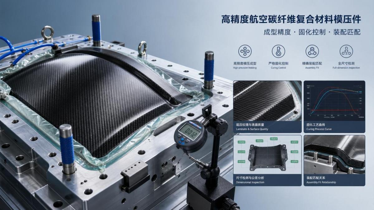
Technical evaluators searching for information on the aerospace carbon fiber molding process are usually not looking for a basic materials overview. Their core question is more practical: how much can molding variability shift the final dimensions of a composite part, and how should that risk be assessed before supplier approval or program release?
The short answer is that dimensional change is not a secondary issue in aerospace composites. It is built into the process. Carbon fiber laminates do not behave like isotropic metals during forming and curing. Fiber orientation, resin chemistry, heat-up rate, tool expansion, vacuum integrity, and cooling profiles all interact. If those variables are not modeled, measured, and controlled, the final part can drift outside tolerance even when the nominal design is correct.
For aerospace assemblies, that drift matters immediately. A flange that pulls inward by a small amount may force trimming, shimming, or rework. A hole pattern that shifts after cure can compromise assembly stack-up. A curved skin panel with inconsistent spring-in may still appear visually acceptable but create load path or fit-up issues once installed. This is why tolerance capability in composite molding must be evaluated as a process outcome, not assumed from CAD intent.
From a sourcing and qualification perspective, the most important point is that tolerance performance is not determined by one variable alone. It is the cumulative result of material system selection, laminate architecture, tooling strategy, cure control, operator discipline, and post-cure verification. Evaluators who focus only on machine lists or autoclave size often miss the true indicators of dimensional stability.
Where dimensional variation begins in composite part production
Variation often starts before molding begins. The laminate design itself affects how the part will move during cure. Symmetric layups generally reduce warpage, while asymmetric stacking sequences can introduce residual stresses and shape distortion. Fiber angles also matter. A laminate dominated by directional plies may respond differently to thermal shrinkage than a quasi-isotropic schedule, especially in contoured parts.
Material behavior is another early source of tolerance shift. Different prepreg systems have different resin flow windows, tack levels, volatile content, and cure shrinkage characteristics. Even within the same qualified system, lot-to-lot variation can influence consolidation and resin distribution. If a supplier cannot show incoming material control, freezer management, out-time discipline, and batch traceability, the dimensional risk rises before the first ply is laid.
Tooling design is equally critical. In aerospace composite work, tools are not neutral fixtures. Their coefficient of thermal expansion, stiffness, venting, surface finish, and geometric compensation strategy directly influence final part dimensions. An aluminum tool and an Invar tool can produce different outcomes under the same cure cycle because the tool-part interaction changes as temperature rises and falls. That difference becomes more pronounced in large or highly contoured structures.
Layup execution also deserves close attention. Ply placement accuracy, wrinkle control, bridging prevention, debulk frequency, and edge management all affect local laminate thickness and consolidation. A technically acceptable ply book does not guarantee a dimensionally stable part if manual execution varies across shifts or operators. For evaluators, this is where process capability and workforce discipline begin to separate top-tier composite suppliers from merely compliant ones.
How cure cycles, resin flow, and tool interaction shift the final part
The cure stage is where many tolerance shifts become locked in. During heat-up, the resin viscosity drops, allowing the laminate to consolidate and conform to the tool. As the resin begins to gel and crosslink, the part loses the ability to relax internal stresses. Any imbalance in pressure application, vacuum condition, resin movement, or thermal distribution can become permanent geometry change.
Cure shrinkage is one of the most misunderstood drivers. Resin systems shrink as they polymerize, but the fibers constrain that shrinkage in directional ways. The result is anisotropic dimensional change. A flat coupon may show low shrinkage in one direction and noticeably different behavior in another. On complex geometries, that anisotropy can produce spring-in, spring-back, flange angle change, or contour mismatch. These effects are not defects in the traditional sense; they are process physics that must be predicted and compensated.
Temperature uniformity inside the tool and across the laminate is another high-value checkpoint. If one region reaches gel earlier than another, the laminate can consolidate unevenly. Thick sections, drop-off zones, core transitions, and bonded reinforcements are especially vulnerable. A supplier that only reports autoclave setpoint but not embedded thermocouple data is giving an incomplete picture of cure quality.
Tool-part interaction during cooling is also important. As the assembly cools, both the tool and laminate contract, but not at the same rate. If the tool constrains the laminate during this stage, residual stresses can build and then release after demolding, causing shape shift. That is why some parts measure differently on-tool, immediately after demold, and again after stabilization. Evaluators should ask when dimensions are measured and whether the supplier has a standard conditioning window before inspection.
Vacuum bagging quality can further influence results. Leaks, poor breather distribution, bridging in the bag, or inconsistent pressure transfer can alter consolidation from one area to another. In aerospace programs, these are not minor shop-floor details. They directly affect thickness, flatness, edge definition, and repeatability across production lots.
Which engineering data points matter most during supplier qualification
For technical evaluators, the best defense against tolerance surprises is a data-driven qualification framework. Instead of asking whether a supplier can make carbon fiber parts, ask whether the supplier can repeatedly hold the specific dimensional and geometric requirements your application needs. That requires evidence tied to process capability, not broad capability statements.
Start with dimensional capability data on representative geometries. Flat panels are not enough if your application includes curved shells, closed sections, co-cured stiffeners, or flange transitions. Ask for measured results across multiple production runs, including profile tolerance, flange angle deviation, hole position after cure or after machining, thickness variation, and stability after trim. If possible, request data by part family rather than generic process brochures.
Thermal process records are another essential input. Review actual cure cycle logs, embedded part thermocouple data, pressure traces, vacuum records, and any cure uniformity studies. The goal is to verify whether the supplier controls the real thermal history of the part, not simply whether the autoclave reached its programmed settings.
Tooling methodology should be examined in detail. Evaluators should understand tool material selection, compensation strategy for spring-in or shrinkage, maintenance intervals, and requalification criteria. A supplier that has robust tooling engineering often shows better dimensional consistency than one relying on repeated trim-and-fit corrections after cure.
Inspection system maturity is equally important. Ask what metrology methods are used, when dimensions are captured, how often first article and in-process checks are repeated, and how nonconformances are trended. For larger aerospace components, laser scanning or CMM-based comparison to CAD can reveal shape distortion patterns that simple hand measurements cannot. Trend data over time is more valuable than one good inspection report.
Finally, review rework and scrap history. A supplier may present acceptable final inspection numbers while masking instability through heavy manual correction. Excessive shimming, repeated trimming, local heating for shape adjustment, or recurring bondline compensation can all indicate that the aerospace carbon fiber molding process is not inherently stable. Technical evaluators should distinguish between “parts passed inspection” and “process consistently produced conforming geometry.”
How to judge tolerance risk before it turns into assembly or service problems
Tolerance risk should be assessed in the context of assembly function, not only drawing compliance. A composite part may fall within standalone dimensional limits and still create downstream problems if it interacts poorly with mating hardware, metallic substructures, or bonded joints. That is why technical evaluation should connect molded geometry to stack-up, load transfer, and service environment.
One useful approach is to classify features by consequence. For example, outer mold line profile on an aerodynamic surface may affect drag or radar behavior. Flange angle variation may affect fastener preload and gap management. Thickness drift near a bonded interface may alter adhesive bondline quality. Hole position changes may force secondary machining strategies that weaken local laminate design margins. Each feature carries a different engineering and program risk.
Environmental stability should also be considered. Composite parts may respond to moisture uptake, thermal cycling, or post-cure aging with slight dimensional changes. In high-precision aerospace assemblies, even small movement after delivery can matter. Suppliers should be able to explain how final tolerances are verified relative to conditioning state and expected service environment.
Another frequent blind spot is the transition from molding to secondary operations. Trimming, drilling, bonding, and insert installation can either correct or amplify earlier variation. If the molded datum scheme is unstable, secondary machining may reference a distorted condition, leading to cumulative error. Evaluators should therefore review not only the molding step, but the full route by which final dimensions are established.
When possible, compare first-article performance to serial production performance. Many suppliers can achieve good early results under elevated engineering attention. The more revealing question is whether the same tolerance control remains after ramp-up, across shifts, tool refurbishments, and material lot changes. Sustainable process capability is more valuable than isolated excellence.
Practical checklist for evaluating a composite supplier’s molding control
For a technical evaluation team, a structured checklist can make supplier comparisons more objective. First, confirm whether the supplier has process-specific dimensional capability data for aerospace composite geometries similar to yours. Generic claims about “tight tolerances” are not enough without actual values, measurement method, and sample size.
Second, verify material control discipline. Review prepreg storage records, out-time logs, lot traceability, and handling standards. Dimensional repeatability begins with material consistency, especially for parts with demanding contour or thickness requirements.
Third, examine tooling rigor. Ask what tool materials are used, how compensation factors were derived, how often tools are inspected, and how wear or thermal distortion is managed over time. Tool engineering is one of the strongest predictors of repeatable molded geometry.
Fourth, review cure control evidence. That includes thermal mapping, embedded thermocouples, vacuum and pressure logs, and documented response plans for interrupted or out-of-window cycles. If cure control data is weak, tolerance data should be treated cautiously.
Fifth, assess operator-dependent risk. Understand how ply placement is standardized, how debulks are scheduled, how bagging quality is verified, and how training is maintained. In many composite shops, dimensional performance is still heavily influenced by execution discipline.
Sixth, evaluate inspection depth. Look for 3D metrology capability, stable datum strategy, repeat measurement timing, and statistical trend analysis. A mature supplier should be able to show how dimensions behave across batches, not just on one accepted part.
Seventh, connect all findings to program impact. If the part is highly loaded, tightly integrated, or expensive to rework downstream, even modest molding variation may justify tighter process surveillance or dual-source benchmarking. Supplier qualification is not only about current conformance; it is about future risk containment.
Conclusion: evaluate the process, not just the part
The main lesson for technical evaluators is clear: the aerospace carbon fiber molding process can absolutely shift final tolerances, and those shifts are often rooted in normal process physics rather than obvious defects. Cure shrinkage, spring-in, tool expansion mismatch, resin flow behavior, and layup variability all influence the final geometry that reaches assembly.
That means composite supplier evaluation should go beyond material certifications, equipment lists, or finished-part pass/fail reports. The more reliable approach is to study how dimensional variation begins, how it is controlled through tooling and cure, how it is measured after demold and secondary operations, and how consistently it performs over time.
For aerospace programs where fit, load transfer, and certification margins are non-negotiable, tolerance capability is not a cosmetic quality metric. It is a core engineering competence. Suppliers that can prove control with real process data, metrology history, and repeatable dimensional outcomes deserve serious consideration. Those that cannot may still produce acceptable prototypes, but they represent a higher risk in production scale and long-term assembly stability.
In practical terms, the right question is not whether a supplier can mold carbon fiber parts. It is whether their molding system can repeatedly deliver the geometry your application requires, under the conditions your program will actually face. That is the standard technical evaluators should use when turning composite capability into procurement confidence.
Search News
Hot Articles
- Carbon Fiber StructuresHow to Specify Aerospace Carbon Fiber Assemblies for Lightweight, Load-Bearing PartsJul 11, 2026
- Machine VisionXiaomi, Alibaba DAMO Academy Drive Open-Source Robotics Model Ecosystem, Lowering Algorithm Development Barriers for Overseas SMEs Adopting Chinese Robotics SolutionsMar 30, 2026
- Cobots & ArmsShanxi 'AI+' Conference Showcases Embodied Intelligence with Multinational Buyer Engagement: Key Industry ImplicationsMar 30, 2026
Popular Tags
Recommended News
 Jul 11, 2026How to Specify Aerospace Carbon Fiber Assemblies for Lightweight, Load-Bearing PartsAerospace carbon fiber assemblies: learn how to specify laminate design, load data, joining methods, and inspection controls for lighter, reliable load-bearing aerospace parts.Elena Rostova (UAV Systems Researcher)
 Mar 30, 2026Xiaomi, Alibaba DAMO Academy Drive Open-Source Robotics Model Ecosystem, Lowering Algorithm Development Barriers for Overseas SMEs Adopting Chinese Robotics SolutionsXiaomi & Alibaba DAMO Academy's open-source robotics models lower algorithm barriers for global SMEs. Boost efficiency in manufacturing, logistics & smart retail with ROS 2 compatible solutions.TSV Data Lab
 Mar 30, 2026Shanxi 'AI+' Conference Showcases Embodied Intelligence with Multinational Buyer Engagement: Key Industry ImplicationsShanxi 'AI+' Conference highlights embodied intelligence with Tesla, Ubtech & Jiantao showcasing multimodal robotics. 40+ global buyers validated tech on-site, creating new B2B channels for industrial automation & AI solutions.Chen Wei (Automation Lead Engineer)
 Mar 30, 2026Zhongguancun Unveils 6G Integrated Sensing-Computing-Intelligence Platform to Empower Embodied Robots for Global Industrial ApplicationsZhongguancun's new 6G platform revolutionizes industrial robotics with <10ms latency, empowering global automotive, logistics & port automation. Discover how this tech boosts China's smart manufacturing exports.TSV Data Lab
 Mar 30, 2026Mech-Mind Tianjin Embodied Intelligence R&D and Production Base Goes Live, Cutting Delivery Time by 20%–30% for Global Customized AMR+Vision SolutionsMech-Mind's Tianjin AMR+Vision production base cuts delivery time by 20%-30% for欧美 & Latin American markets. Discover how this PLd-certified facility accelerates customized robotics solutions for smart manufacturing and logistics.Chen Wei (Automation Lead Engineer)
 Mar 30, 2026Boao Forum Reveals 'Co-evolution of Big and Small Brains' Trend in Humanoid Robots, China's Embodied Intelligence Accelerates Adaptation to Overseas Manufacturing Service ScenariosDiscover how China's humanoid robots, featuring 'Co-evolution of Big and Small Brains,' are revolutionizing global manufacturing. Learn about Embodied Tian Gong 3.0's ISO compliance and overseas deployment at Boao Forum 2026.Chen Wei (Automation Lead Engineer)
 Mar 30, 2026China Railway Industrial Secures Patent for Embodied Robotics in Material Handling, Boosting High-Precision Delivery Capabilities for Overseas Infrastructure and Manufacturing ProjectsChina Railway Industrial's new patent for embodied robotics in material handling boosts high-precision delivery for global infrastructure & manufacturing. Discover how this innovation enhances logistics accuracy in automotive, rail transit & EPC projects.Chen Wei (Automation Lead Engineer)
 Sep 28, 2026Spindle Runout Measurement in Germany: DIN Standards, Methods, and Acceptance LimitsSpindle runout measurement Germany: explore DIN standards, proven methods, acceptance limits, and audit-ready practices for reliable machining quality.Dr. Marcus Vance
 Sep 27, 2026How to Select Wall-Mount Edge Devices for Space-Constrained Factory NetworksWall mount edge devices for space-constrained factories: evaluate workload, thermal design, power resilience, cable access, and network reliability for smarter deployments.TSV Data Lab
 Sep 26, 2026Machining Tolerance Analysis: How to Set Limits That Meet Function and Cost TargetsMachining tolerance analysis: learn how to set functional limits, control tolerance stacks, reduce inspection risk, and balance precision with production cost.Dr. Marcus Vance
 Sep 25, 2026How to Evaluate an Industrial Infrastructure Data Platform for Multi-Site OperationsIndustrial infrastructure data platform evaluation guide for multi-site operations: compare data quality, edge resilience, interoperability, governance, and scalable proof-of-value criteria.Victor Lin (Chief Software Architect)
 Sep 24, 2026How to Select Machine Vision Optics for Accurate Inspection at Different Working DistancesMachine vision optics selection guide for accurate inspection at every working distance. Compare FOV, pixel scale, DOF, distortion, lighting, and telecentric options.TSV Data Lab
 Sep 23, 2026How to Evaluate a Machine Vision System Integrator for High-Speed Inspection LinesChoose a machine vision system integrator with proven expertise in high-speed inspection, reliable reject timing, robust optics, and measurable acceptance criteria.TSV Data Lab
 Sep 28, 2026When is a SCADA API the right choice for connecting plant systems?SCADA API guide: learn when governed plant data integration improves traceability, security, and scalability—without compromising real-time control.Victor Lin (Chief Software Architect)
 Sep 27, 2026How SCADA data integration improves traceability across production linesSCADA data integration connects production-line data to improve traceability, accelerate quality investigations, and strengthen safety decisions.Victor Lin (Chief Software Architect)
 Sep 26, 2026What to define before starting SCADA integration planningSCADA integration planning starts with clear scope, control boundaries, data models, cybersecurity, and testing. Discover the definitions that reduce risk and costly rework.Victor Lin (Chief Software Architect)
 Sep 25, 2026How a smart factory with Industrial IoT reduces production blind spotsDiscover how a smart factory with Industrial IoT turns real-time machine, quality, and workflow data into actionable insights that reduce production blind spots and delivery risks.Victor Lin (Chief Software Architect)
 Sep 24, 2026When does Industrial IoT make smart manufacturing easier to scale?Smart manufacturing Industrial IoT scales when trusted data, interoperable systems, and secure workflows turn connected assets into measurable gains.TSV Data Lab
 Sep 23, 2026What drives ultra-precision machining cost at 1-micron tolerance?Ultra precision machining cost per part at 1 micron tolerance depends on process, material, metrology, and yield. Learn how to compare quotes confidently.Dr. Marcus Vance
 Sep 22, 2026Drone Engine-T550CC Applications: Build the UAV Power System Around the MissionAn application guide for Drone Engine-T550CC integration, covering payload planning, airframe matching, cooling, fuel, vibration, test procedures, documentation, and service preparation.Elena Rostova (UAV Systems Researcher)
 Sep 22, 2026How to Evaluate Industrial Edge Computing Vendors for Factory DeploymentIndustrial edge computing vendor evaluation guide for factories: compare latency, protocol fit, reliability, security, and lifecycle support before deployment.TSV Data Lab
 Sep 21, 2026Drone Payload Integration: Matching Power, Data, and Center of Gravity for Reliable FlightsDrone payload integration made practical: balance power, data, center of gravity, and endurance to build safer, more reliable mission-ready flights.Elena Rostova (UAV Systems Researcher)
 Sep 20, 2026Autonomous Navigation Pricing: Cost Drivers and Budget Benchmarks for AMR ProjectsAutonomous navigation price explained: compare AMR cost drivers, software, sensors, integration, safety, and lifecycle budgets to build a scalable project plan.Chen Wei (Automation Lead Engineer)
 Sep 19, 2026How to Scope Automation Integration Services for Multi-System Factory ProjectsAutomation integration services: learn how to scope multi-system factory projects with clear workflows, interface contracts, safety boundaries, and acceptance criteria.Victor Lin (Chief Software Architect)























