
Machine vision for quality inspection works best with stable parts
Publication Date
author
Machine vision for quality inspection delivers the highest accuracy when parts remain stable, repeatable, and precisely positioned. For quality and safety managers, this is not a minor setup detail but a core factor that shapes detection reliability, false reject rates, and traceable inspection data. In high-stakes manufacturing, stable parts create the conditions for measurable engineering truth.
What machine vision for quality inspection really means
Machine vision for quality inspection is the use of cameras, optics, lighting, software, and industrial controls to evaluate whether a part, assembly, label, or surface meets defined requirements. It may confirm dimensions, check presence or absence, verify alignment, detect scratches, read codes, or classify defects. In modern factories, it also supports traceability, process discipline, and safety by producing digital evidence that can be reviewed, stored, and connected to production events.
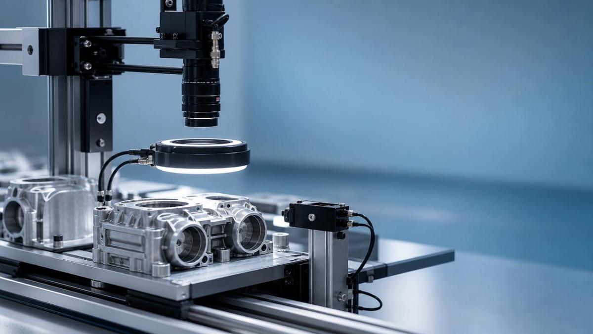
However, the system does not inspect a part in isolation. It inspects an image formed under specific physical conditions. If those conditions change from one cycle to the next, the image changes even when the part does not. That is why machine vision for quality inspection works best with stable parts. Stability reduces variation at the source, allowing the camera and software to focus on true quality signals instead of chasing noise created by motion, vibration, tilt, or inconsistent positioning.
For quality control personnel and safety managers, this distinction matters. A vision system that performs well during a demonstration can fail in daily production if part presentation is inconsistent. The technical lesson is simple: image quality is not only about sensor resolution or AI capability. It is also about fixturing, conveyance control, part orientation, and timing accuracy.
Why stable parts matter so much in real production
In many facilities, inspection problems are first blamed on software thresholds, lens settings, or operator training. Yet the root cause is often unstable part handling. A part that rotates slightly, shifts laterally, bounces on a conveyor, or sits at a different height can alter contrast, edge sharpness, and measurement geometry. Even a high-end vision setup may then generate false rejects, missed defects, or inconsistent results across shifts.
Stable parts improve machine vision for quality inspection in several direct ways. First, they preserve geometric consistency, which is essential for dimensional checks and pattern matching. Second, they keep lighting behavior repeatable, reducing reflections and shadow changes. Third, they improve cycle predictability, allowing the camera trigger to capture the same inspection moment every time. Fourth, they reduce the need for excessive software compensation, which often adds complexity without fully solving the mechanical source of variation.
This aligns closely with the TSV view of engineering truth: reliable inspection begins with measurable physical control. Parameters do not lie, and tolerances dictate success. When manufacturers treat part stability as a design requirement rather than an afterthought, inspection data becomes more trustworthy and more useful for process improvement.
Industry context: why the topic is gaining attention
Across the broader industrial landscape, manufacturers are under pressure to increase throughput while proving compliance, reducing scrap, and protecting downstream safety. At the same time, production lines are becoming more automated, more data-driven, and more interconnected. This creates strong demand for machine vision for quality inspection, because visual verification can scale faster and more consistently than manual inspection in many tasks.
But higher adoption also exposes a common misunderstanding: digital inspection cannot fully compensate for unstable mechanics. In sectors ranging from electronics and packaging to metalworking, automotive components, logistics, and industrial equipment assembly, the best-performing systems are usually not those with the most marketing claims. They are the systems built on controlled part presentation, stable motion, robust lighting, and clear pass-fail criteria.
For safety managers, the issue extends beyond product defects. Unstable parts can lead to unreliable code reading, incorrect part verification, or missed assembly conditions that affect field safety, maintenance risk, or recall exposure. In that sense, stable inspection conditions support not only quality performance but also operational accountability.
Where stable-part inspection creates the most value
The value of machine vision for quality inspection becomes easiest to see in tasks where the pass-fail standard is narrow and the production rate is high. In these conditions, stable parts allow the system to run faster, with fewer manual interventions and more credible data.
Typical high-value use cases include dimensional verification of machined parts, label and print inspection in packaging, seal integrity checks, connector position checks, weld and bond verification, surface defect detection, and 2D code or serial number reading for traceability. In each case, the physical consistency of the part directly influences whether the image contains enough repeatable information for accurate inspection.
For quality teams, this means fewer disputed results and better root-cause analysis. For safety teams, it means greater confidence that critical features are being checked under controlled and auditable conditions. For operations leaders, it means more stable yield, lower rework, and a shorter path from inspection alarms to corrective action.
Common application categories and their stability needs
Not all vision tasks depend on stability in the same way. Some applications can tolerate minor position shifts through robust pattern location tools. Others, especially precision measurement or reflective surface inspection, require tight mechanical control. Understanding this difference helps teams deploy machine vision for quality inspection more effectively.
What quality and safety managers should evaluate first
When assessing machine vision for quality inspection, many organizations start with camera specifications. A better starting point is process stability. Ask whether the part arrives in the same location, at the same height, with the same orientation, and under the same lighting influence every cycle. If the answer is no, vision performance will likely vary no matter how advanced the software appears.
A disciplined evaluation should cover five areas. First, define the quality characteristic in engineering terms: tolerance, defect size, allowed orientation range, acceptable contrast, and required traceability outcome. Second, study part presentation: fixture design, conveyor behavior, stop accuracy, vibration, and transfer repeatability. Third, validate imaging conditions: lens selection, field of view, depth of field, exposure time, and lighting geometry. Fourth, test under real production variation rather than ideal samples only. Fifth, connect the inspection output to response rules, data logging, and containment actions.
This approach reflects a data-first mindset. Instead of asking whether the vision system is “smart,” ask whether the full inspection process is measurable, stable, and explainable. That is the basis for useful benchmarking and credible quality records.
Practical recommendations for improving stable-part inspection
The good news is that part stability can often be improved without redesigning the entire line. In many cases, the highest return comes from straightforward engineering controls. Add guides that remove lateral drift. Use nests or pallets to standardize orientation. Reduce vibration at the inspection station. Synchronize triggers with encoder feedback rather than loose timing assumptions. Control part height before imaging. For reflective or glossy components, stabilize both the part and the lighting angle together.
It is also wise to separate what software should correct from what mechanics should prevent. Vision tools can compensate for minor location differences, but they should not be expected to overcome severe bounce, random rotation, or unstable stop positions. Overreliance on compensation can make the system harder to validate and harder to maintain across product changes.
For safety-sensitive environments, include challenge testing in the validation plan. Intentionally vary part position, speed, and lighting within expected limits to determine where performance degrades. This produces a more honest operating window and helps teams define escalation rules before defects or incidents occur.
Longer-term business significance
Stable machine vision for quality inspection is not only a technical improvement; it is a business capability. Reliable inspection data reduces sorting costs, speeds corrective action, and strengthens supplier and customer communication. It also supports continuous improvement because trends in defect type, location, and frequency become easier to trust when inspection conditions are controlled.
For organizations managing multi-site production or supplier qualification, the principle is especially important. Standardized part presentation and validated imaging conditions make it easier to compare results across lines and plants. That creates the kind of engineering transparency that advanced manufacturing increasingly requires.
Conclusion and next steps
Machine vision for quality inspection delivers its best results when the inspected part is stable, repeatable, and physically well-controlled. That principle may sound basic, but it determines whether inspection becomes a source of engineering truth or a source of avoidable noise. For quality control and safety leaders, the priority is clear: treat part stability as part of the inspection specification, not as a background assumption.
If your organization is reviewing vision performance, start by measuring how parts arrive at the camera, not just how the software scores the image. Build from tolerances, motion control, lighting discipline, and traceable data logic. In practical terms, that is how machine vision for quality inspection becomes more accurate, more auditable, and more valuable to the wider manufacturing system.
Search News
Hot Articles
- Carbon Fiber StructuresHow to Specify Aerospace Carbon Fiber Assemblies for Lightweight, Load-Bearing PartsJul 11, 2026
- Machine VisionXiaomi, Alibaba DAMO Academy Drive Open-Source Robotics Model Ecosystem, Lowering Algorithm Development Barriers for Overseas SMEs Adopting Chinese Robotics SolutionsMar 30, 2026
- Cobots & ArmsShanxi 'AI+' Conference Showcases Embodied Intelligence with Multinational Buyer Engagement: Key Industry ImplicationsMar 30, 2026
Popular Tags
Recommended News
 Jul 11, 2026How to Specify Aerospace Carbon Fiber Assemblies for Lightweight, Load-Bearing PartsAerospace carbon fiber assemblies: learn how to specify laminate design, load data, joining methods, and inspection controls for lighter, reliable load-bearing aerospace parts.Elena Rostova (UAV Systems Researcher)
 Mar 30, 2026Xiaomi, Alibaba DAMO Academy Drive Open-Source Robotics Model Ecosystem, Lowering Algorithm Development Barriers for Overseas SMEs Adopting Chinese Robotics SolutionsXiaomi & Alibaba DAMO Academy's open-source robotics models lower algorithm barriers for global SMEs. Boost efficiency in manufacturing, logistics & smart retail with ROS 2 compatible solutions.TSV Data Lab
 Mar 30, 2026Shanxi 'AI+' Conference Showcases Embodied Intelligence with Multinational Buyer Engagement: Key Industry ImplicationsShanxi 'AI+' Conference highlights embodied intelligence with Tesla, Ubtech & Jiantao showcasing multimodal robotics. 40+ global buyers validated tech on-site, creating new B2B channels for industrial automation & AI solutions.Chen Wei (Automation Lead Engineer)
 Mar 30, 2026Zhongguancun Unveils 6G Integrated Sensing-Computing-Intelligence Platform to Empower Embodied Robots for Global Industrial ApplicationsZhongguancun's new 6G platform revolutionizes industrial robotics with <10ms latency, empowering global automotive, logistics & port automation. Discover how this tech boosts China's smart manufacturing exports.TSV Data Lab
 Mar 30, 2026Mech-Mind Tianjin Embodied Intelligence R&D and Production Base Goes Live, Cutting Delivery Time by 20%–30% for Global Customized AMR+Vision SolutionsMech-Mind's Tianjin AMR+Vision production base cuts delivery time by 20%-30% for欧美 & Latin American markets. Discover how this PLd-certified facility accelerates customized robotics solutions for smart manufacturing and logistics.Chen Wei (Automation Lead Engineer)
 Mar 30, 2026Boao Forum Reveals 'Co-evolution of Big and Small Brains' Trend in Humanoid Robots, China's Embodied Intelligence Accelerates Adaptation to Overseas Manufacturing Service ScenariosDiscover how China's humanoid robots, featuring 'Co-evolution of Big and Small Brains,' are revolutionizing global manufacturing. Learn about Embodied Tian Gong 3.0's ISO compliance and overseas deployment at Boao Forum 2026.Chen Wei (Automation Lead Engineer)
 Mar 30, 2026China Railway Industrial Secures Patent for Embodied Robotics in Material Handling, Boosting High-Precision Delivery Capabilities for Overseas Infrastructure and Manufacturing ProjectsChina Railway Industrial's new patent for embodied robotics in material handling boosts high-precision delivery for global infrastructure & manufacturing. Discover how this innovation enhances logistics accuracy in automotive, rail transit & EPC projects.Chen Wei (Automation Lead Engineer)
 Sep 28, 2026Spindle Runout Measurement in Germany: DIN Standards, Methods, and Acceptance LimitsSpindle runout measurement Germany: explore DIN standards, proven methods, acceptance limits, and audit-ready practices for reliable machining quality.Dr. Marcus Vance
 Sep 27, 2026How to Select Wall-Mount Edge Devices for Space-Constrained Factory NetworksWall mount edge devices for space-constrained factories: evaluate workload, thermal design, power resilience, cable access, and network reliability for smarter deployments.TSV Data Lab
 Sep 26, 2026Machining Tolerance Analysis: How to Set Limits That Meet Function and Cost TargetsMachining tolerance analysis: learn how to set functional limits, control tolerance stacks, reduce inspection risk, and balance precision with production cost.Dr. Marcus Vance
 Sep 25, 2026How to Evaluate an Industrial Infrastructure Data Platform for Multi-Site OperationsIndustrial infrastructure data platform evaluation guide for multi-site operations: compare data quality, edge resilience, interoperability, governance, and scalable proof-of-value criteria.Victor Lin (Chief Software Architect)
 Sep 24, 2026How to Select Machine Vision Optics for Accurate Inspection at Different Working DistancesMachine vision optics selection guide for accurate inspection at every working distance. Compare FOV, pixel scale, DOF, distortion, lighting, and telecentric options.TSV Data Lab
 Sep 23, 2026How to Evaluate a Machine Vision System Integrator for High-Speed Inspection LinesChoose a machine vision system integrator with proven expertise in high-speed inspection, reliable reject timing, robust optics, and measurable acceptance criteria.TSV Data Lab
 Sep 28, 2026When is a SCADA API the right choice for connecting plant systems?SCADA API guide: learn when governed plant data integration improves traceability, security, and scalability—without compromising real-time control.Victor Lin (Chief Software Architect)
 Sep 27, 2026How SCADA data integration improves traceability across production linesSCADA data integration connects production-line data to improve traceability, accelerate quality investigations, and strengthen safety decisions.Victor Lin (Chief Software Architect)
 Sep 26, 2026What to define before starting SCADA integration planningSCADA integration planning starts with clear scope, control boundaries, data models, cybersecurity, and testing. Discover the definitions that reduce risk and costly rework.Victor Lin (Chief Software Architect)
 Sep 25, 2026How a smart factory with Industrial IoT reduces production blind spotsDiscover how a smart factory with Industrial IoT turns real-time machine, quality, and workflow data into actionable insights that reduce production blind spots and delivery risks.Victor Lin (Chief Software Architect)
 Sep 24, 2026When does Industrial IoT make smart manufacturing easier to scale?Smart manufacturing Industrial IoT scales when trusted data, interoperable systems, and secure workflows turn connected assets into measurable gains.TSV Data Lab
 Sep 23, 2026What drives ultra-precision machining cost at 1-micron tolerance?Ultra precision machining cost per part at 1 micron tolerance depends on process, material, metrology, and yield. Learn how to compare quotes confidently.Dr. Marcus Vance
 Sep 22, 2026Drone Engine-T550CC Applications: Build the UAV Power System Around the MissionAn application guide for Drone Engine-T550CC integration, covering payload planning, airframe matching, cooling, fuel, vibration, test procedures, documentation, and service preparation.Elena Rostova (UAV Systems Researcher)
 Sep 22, 2026How to Evaluate Industrial Edge Computing Vendors for Factory DeploymentIndustrial edge computing vendor evaluation guide for factories: compare latency, protocol fit, reliability, security, and lifecycle support before deployment.TSV Data Lab
 Sep 21, 2026Drone Payload Integration: Matching Power, Data, and Center of Gravity for Reliable FlightsDrone payload integration made practical: balance power, data, center of gravity, and endurance to build safer, more reliable mission-ready flights.Elena Rostova (UAV Systems Researcher)
 Sep 20, 2026Autonomous Navigation Pricing: Cost Drivers and Budget Benchmarks for AMR ProjectsAutonomous navigation price explained: compare AMR cost drivers, software, sensors, integration, safety, and lifecycle budgets to build a scalable project plan.Chen Wei (Automation Lead Engineer)
 Sep 19, 2026How to Scope Automation Integration Services for Multi-System Factory ProjectsAutomation integration services: learn how to scope multi-system factory projects with clear workflows, interface contracts, safety boundaries, and acceptance criteria.Victor Lin (Chief Software Architect)























