Machine Vision Lens Calibration Explained: Fixing Distortion and Measurement Errors
Publication Date
author
Machine Vision Lens Calibration Explained: Fixing Distortion and Measurement Errors
In precision imaging, even a high-end camera can produce unreliable results if distortion is left uncorrected.
Machine vision lens calibration turns raw pixels into trustworthy measurements.
It helps reduce error, verify optical performance, and stabilize inspection outcomes across shifts, fixtures, and production lots.
This matters when pass or fail decisions depend on tenths of a millimeter, or even less.
Why Machine Vision Lens Calibration Matters
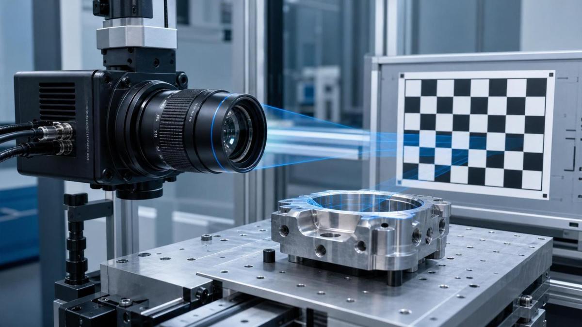
A lens does not map the real world onto the sensor perfectly.
Straight edges can bow outward or inward.
Objects near the image edge may appear stretched, compressed, or shifted.
Without machine vision lens calibration, those distortions flow directly into measurements.
The result is not just a cosmetic flaw.
It can create false rejects, missed defects, and unstable gauge correlation.
In practice, uncalibrated optics often show up as drifting dimensions between the image center and the corners.
That is usually the first sign that pixels are not equal everywhere in the field of view.
For any technical review, calibration is the baseline check before trusting measurement data.
What Calibration Actually Corrects
Machine vision lens calibration estimates how the lens and camera distort geometry.
It then builds a correction model for later image processing or measurement conversion.
Most industrial systems correct several error sources at once:
- Radial distortion, where straight lines curve near the outer image area.
- Tangential distortion, caused by lens element misalignment.
- Perspective error, especially when the camera is not square to the target.
- Pixel scaling differences across X and Y directions.
- Principal point offset, where the optical center shifts from the sensor center.
This is why machine vision lens calibration is more than assigning one pixel-to-millimeter factor.
That simple shortcut can work for rough positioning, but it is not enough for precision inspection.
Common Causes of Measurement Drift
Even after initial setup, measurement error can come back.
That usually means the optical stack or the operating environment changed.
The most common drift sources include:
- Focus changes after vibration, maintenance, or lens replacement.
- Working distance shifts caused by fixture wear or robot repositioning.
- Temperature effects that slightly alter lens geometry or mounting position.
- Sensor swaps with different pixel pitch or alignment.
- Telecentric assumptions applied to non-telecentric lenses.
From a recent market shift, more systems now combine edge AI with compact optics.
That saves space, but it often tightens tolerance on mounting repeatability.
So machine vision lens calibration should be treated as a maintained process, not a one-time checkbox.
How the Calibration Process Works
A typical machine vision lens calibration workflow is straightforward when done carefully.
The quality of the result depends more on discipline than on software features.
1. Select the right calibration target
Use a certified dot grid, checkerboard, or precision plate matched to your field of view.
The target itself must have tighter accuracy than the measurement requirement.
2. Lock the imaging setup
Focus, aperture, lighting, working distance, and camera angle should be fixed before capture.
Changing any of these after calibration weakens the model.
3. Capture multiple views
Record the target at different positions and orientations across the usable image area.
This gives the software enough information to estimate lens distortion correctly.
4. Solve the camera model
The software calculates intrinsic parameters and distortion coefficients.
It also reports residual error, often as reprojection error.
5. Validate with known dimensions
Do not stop at the software score.
Measure certified features at the center and edges of the image.
This confirms whether the machine vision lens calibration supports the actual inspection task.
Choosing Between Telecentric and Standard Lenses
Calibration strategy depends heavily on lens type.
A standard lens is flexible and cost-effective, but perspective and magnification variation are more noticeable.
A telecentric lens reduces those issues by keeping magnification more stable with object height changes.
That said, telecentric optics are not distortion-free by definition.
They still benefit from machine vision lens calibration, especially in metrology-grade applications.
For procurement and technical evaluation, this choice affects both optical risk and calibration burden.
What Good Calibration Data Looks Like
A low reprojection error is useful, but it is not the whole story.
Good machine vision lens calibration should produce repeatable physical measurements under normal operating conditions.
Look for these validation signals:
- Consistent measurements at the center, corners, and mid-field.
- Stable results after restart or shift change.
- Low variation between multiple calibrated units.
- Clear documentation of target specification and capture conditions.
- Verified correlation against a traceable reference gauge.
A stronger signal is when error remains bounded after fixture changeover or preventive maintenance.
That shows the calibration method is robust, not just tuned for one ideal moment.
Frequent Mistakes in Real Projects
Many inspection issues come from avoidable setup habits, not from bad software.
These are the mistakes that cause the most trouble:
- Calibrating with one focus, then running production at another.
- Using a paper target for a high-accuracy requirement.
- Ignoring edge-of-field measurement performance.
- Skipping recalibration after lens removal or camera impact.
- Accepting vendor accuracy claims without traceable validation data.
This is where a data-first review process helps.
Parameters should be tied to operating conditions, not presented as isolated best-case numbers.
For machine vision lens calibration, tolerances only mean something when the test method is visible.
A Practical Evaluation Checklist
When reviewing a camera-lens package, use a checklist that connects calibration to inspection risk.
- Confirm the required dimensional tolerance and field coverage.
- Request distortion data before and after machine vision lens calibration.
- Verify the calibration target grade and certificate.
- Check how residual error was measured and reported.
- Ask whether recalibration is needed after focus or distance changes.
- Review measurement performance at image edges, not only at center.
- Validate results with a traceable part or master gauge.
This approach makes supplier comparisons more meaningful.
It also shortens trial-and-error cycles during line integration.
Machine vision lens calibration is not just an optical detail.
It is a control point for data integrity, supplier qualification, and inspection repeatability.
When distortion is corrected properly, measurements become more reliable and more defensible.
That is the standard worth holding, especially where engineering decisions depend on every pixel.
Search News
Hot Articles
- Carbon Fiber StructuresHow to Specify Aerospace Carbon Fiber Assemblies for Lightweight, Load-Bearing PartsJul 11, 2026
- Machine VisionXiaomi, Alibaba DAMO Academy Drive Open-Source Robotics Model Ecosystem, Lowering Algorithm Development Barriers for Overseas SMEs Adopting Chinese Robotics SolutionsMar 30, 2026
- Cobots & ArmsShanxi 'AI+' Conference Showcases Embodied Intelligence with Multinational Buyer Engagement: Key Industry ImplicationsMar 30, 2026
Popular Tags
Recommended News
 Jul 11, 2026How to Specify Aerospace Carbon Fiber Assemblies for Lightweight, Load-Bearing PartsAerospace carbon fiber assemblies: learn how to specify laminate design, load data, joining methods, and inspection controls for lighter, reliable load-bearing aerospace parts.Elena Rostova (UAV Systems Researcher)
 Mar 30, 2026Xiaomi, Alibaba DAMO Academy Drive Open-Source Robotics Model Ecosystem, Lowering Algorithm Development Barriers for Overseas SMEs Adopting Chinese Robotics SolutionsXiaomi & Alibaba DAMO Academy's open-source robotics models lower algorithm barriers for global SMEs. Boost efficiency in manufacturing, logistics & smart retail with ROS 2 compatible solutions.TSV Data Lab
 Mar 30, 2026Shanxi 'AI+' Conference Showcases Embodied Intelligence with Multinational Buyer Engagement: Key Industry ImplicationsShanxi 'AI+' Conference highlights embodied intelligence with Tesla, Ubtech & Jiantao showcasing multimodal robotics. 40+ global buyers validated tech on-site, creating new B2B channels for industrial automation & AI solutions.Chen Wei (Automation Lead Engineer)
 Mar 30, 2026Zhongguancun Unveils 6G Integrated Sensing-Computing-Intelligence Platform to Empower Embodied Robots for Global Industrial ApplicationsZhongguancun's new 6G platform revolutionizes industrial robotics with <10ms latency, empowering global automotive, logistics & port automation. Discover how this tech boosts China's smart manufacturing exports.TSV Data Lab
 Mar 30, 2026Mech-Mind Tianjin Embodied Intelligence R&D and Production Base Goes Live, Cutting Delivery Time by 20%–30% for Global Customized AMR+Vision SolutionsMech-Mind's Tianjin AMR+Vision production base cuts delivery time by 20%-30% for欧美 & Latin American markets. Discover how this PLd-certified facility accelerates customized robotics solutions for smart manufacturing and logistics.Chen Wei (Automation Lead Engineer)
 Mar 30, 2026Boao Forum Reveals 'Co-evolution of Big and Small Brains' Trend in Humanoid Robots, China's Embodied Intelligence Accelerates Adaptation to Overseas Manufacturing Service ScenariosDiscover how China's humanoid robots, featuring 'Co-evolution of Big and Small Brains,' are revolutionizing global manufacturing. Learn about Embodied Tian Gong 3.0's ISO compliance and overseas deployment at Boao Forum 2026.Chen Wei (Automation Lead Engineer)
 Mar 30, 2026China Railway Industrial Secures Patent for Embodied Robotics in Material Handling, Boosting High-Precision Delivery Capabilities for Overseas Infrastructure and Manufacturing ProjectsChina Railway Industrial's new patent for embodied robotics in material handling boosts high-precision delivery for global infrastructure & manufacturing. Discover how this innovation enhances logistics accuracy in automotive, rail transit & EPC projects.Chen Wei (Automation Lead Engineer)
 Sep 25, 2026How to Evaluate an Industrial Infrastructure Data Platform for Multi-Site OperationsIndustrial infrastructure data platform evaluation guide for multi-site operations: compare data quality, edge resilience, interoperability, governance, and scalable proof-of-value criteria.Victor Lin (Chief Software Architect)
 Sep 24, 2026How to Select Machine Vision Optics for Accurate Inspection at Different Working DistancesMachine vision optics selection guide for accurate inspection at every working distance. Compare FOV, pixel scale, DOF, distortion, lighting, and telecentric options.TSV Data Lab
 Sep 23, 2026How to Evaluate a Machine Vision System Integrator for High-Speed Inspection LinesChoose a machine vision system integrator with proven expertise in high-speed inspection, reliable reject timing, robust optics, and measurable acceptance criteria.TSV Data Lab
 Sep 25, 2026How a smart factory with Industrial IoT reduces production blind spotsDiscover how a smart factory with Industrial IoT turns real-time machine, quality, and workflow data into actionable insights that reduce production blind spots and delivery risks.Victor Lin (Chief Software Architect)
 Sep 24, 2026When does Industrial IoT make smart manufacturing easier to scale?Smart manufacturing Industrial IoT scales when trusted data, interoperable systems, and secure workflows turn connected assets into measurable gains.TSV Data Lab
 Sep 23, 2026What drives ultra-precision machining cost at 1-micron tolerance?Ultra precision machining cost per part at 1 micron tolerance depends on process, material, metrology, and yield. Learn how to compare quotes confidently.Dr. Marcus Vance
 Sep 22, 2026Drone Engine-T550CC Applications: Build the UAV Power System Around the MissionAn application guide for Drone Engine-T550CC integration, covering payload planning, airframe matching, cooling, fuel, vibration, test procedures, documentation, and service preparation.Elena Rostova (UAV Systems Researcher)
 Sep 22, 2026How to Evaluate Industrial Edge Computing Vendors for Factory DeploymentIndustrial edge computing vendor evaluation guide for factories: compare latency, protocol fit, reliability, security, and lifecycle support before deployment.TSV Data Lab
 Sep 21, 2026Drone Payload Integration: Matching Power, Data, and Center of Gravity for Reliable FlightsDrone payload integration made practical: balance power, data, center of gravity, and endurance to build safer, more reliable mission-ready flights.Elena Rostova (UAV Systems Researcher)
 Sep 20, 2026Autonomous Navigation Pricing: Cost Drivers and Budget Benchmarks for AMR ProjectsAutonomous navigation price explained: compare AMR cost drivers, software, sensors, integration, safety, and lifecycle budgets to build a scalable project plan.Chen Wei (Automation Lead Engineer)
 Sep 19, 2026How to Scope Automation Integration Services for Multi-System Factory ProjectsAutomation integration services: learn how to scope multi-system factory projects with clear workflows, interface contracts, safety boundaries, and acceptance criteria.Victor Lin (Chief Software Architect)
 Sep 18, 2026Selecting UAV Aerospace Structural Parts for Strength, Weight, and Fatigue LifeUAV aerospace structural parts guide: compare strength, weight, stiffness, fatigue life, joints, and traceability to select reliable flight-ready components.Elena Rostova (UAV Systems Researcher)
 Sep 17, 2026Selecting Commercial Drone Payloads for European Inspection ProjectsCommercial drone payloads Europe: learn how to select RGB, thermal and LiDAR systems for compliant, reliable inspection data and better project outcomes.Elena Rostova (UAV Systems Researcher)
 Sep 16, 2026Machining Tolerance Validation: How to Verify Critical Dimensions Before Production ReleaseMachining tolerance analysis validation: verify critical dimensions, measurement systems, process capability, and tolerance stacks before production release.Dr. Marcus Vance
 Sep 15, 2026AGV Tape Guidance vs Laser Navigation: Which Fits Your Warehouse Layout?AGV tape guidance comparison: discover how tape and laser navigation fit changing warehouse layouts, docking needs, floor conditions, maintenance, and route flexibility.Chen Wei (Automation Lead Engineer)
 Sep 14, 2026How Point Cloud Analytics Improves Asset Inspection Workflows Across GCC ProjectsPoint cloud analytics GCC helps project leaders improve asset inspections with accurate change detection, safer workflows, and faster maintenance decisions.TSV Data Lab
 Sep 13, 2026How Aerospace Manufacturers Can Build a Digital Thread From Design to Certified ProductionDigital manufacturing for aerospace: learn how to build a traceable digital thread from design through certified production, supplier control, and audit-ready compliance.Victor Lin (Chief Software Architect)