Machine Vision 3D Measurement Systems: Which Parts, Tolerances, and Line Speeds Fit Best?
Publication Date
author
Why machine vision 3D measurement systems vary so much by production context

Machine vision 3D measurement systems earn value when geometry matters more than appearance alone. That usually means parts with height variation, hidden edge conditions, or tolerance windows too narrow for manual checks.
In practice, the better question is not whether 3D inspection sounds advanced. It is whether the part shape, tolerance stack, and cycle time justify the sensing method, resolution, and processing load.
That distinction matters across mixed industries. A stamped bracket, a turbine blade, a molded housing, and a battery tray may all need dimensional control, but not the same kind.
TechStat Vanguard often frames this issue through one principle: parameters do not lie. For machine vision 3D measurement systems, usable truth comes from fit between measurement task and factory reality.
The real selection logic sits where part complexity, allowable deviation, reflective behavior, vibration, and conveyor speed intersect. That is where good systems separate from expensive mismatches.
Actual use cases start with part geometry, not with camera claims
Flat or near-flat parts often create the first misunderstanding. Many teams assume machine vision 3D measurement systems are unnecessary if 2D cameras already read length and hole position.
That holds only when the risk is planar. If warpage, bow, twist, dent depth, weld bead height, or step difference affects function, 3D becomes the more relevant measurement language.
Stamped metal parts are a good example. Their edges may be easy to detect in 2D, yet springback and flange angle drift often drive downstream fit problems.
Machine vision 3D measurement systems fit best here when the line needs rapid checks on form change, not just pass-fail imaging. Structured light or laser triangulation usually performs better than generic area imaging.
Plastic housings create a different pattern. The challenge is less about sharp deformation and more about sink marks, rib height consistency, connector seating planes, and cumulative dimensional drift after cooling.
For machined parts, the judgment becomes tighter. If tolerances move into tens of microns, the line must distinguish between inspection for process screening and metrology for final certification.
Where tolerance bands change the answer
Not every tolerance band supports inline 3D measurement equally well. Broader tolerances allow faster scanning and more forgiving mounting. Narrower bands demand better fixturing, calibration discipline, and thermal stability.
A practical rule is to compare system repeatability with the actual acceptance band, not the brochure resolution. Resolution alone says little about whether machine vision 3D measurement systems can control a live line.
This is why one factory may see strong return from machine vision 3D measurement systems, while another still needs offline CMM confirmation for critical dimensions.
High-speed lines reward different 3D choices than precision cells
Line speed changes everything. A slower precision cell can afford denser point clouds, longer exposure control, and more complex point registration.
A high-speed conveyor cannot. Here, machine vision 3D measurement systems must trade some detail for stability, deterministic processing, and tight integration with triggers and reject mechanisms.
This is common in packaging hardware, consumer electronics frames, and automotive subassemblies. The main issue is not whether a point cloud looks rich. It is whether measurements stay consistent at full takt.
The same sensor may perform well at pilot speed and fail at production speed because vibration, part spacing, or motion blur shifts the usable dataset. That gap is often ignored during early evaluation.
In a slower aerospace or medical machining environment, the economics reverse. Fewer parts justify deeper measurement if the captured data prevents costly escapes or rework.
A quick way to judge line-speed fit
- Check required scan time against real conveyor spacing, not theoretical part pitch.
- Measure repeatability during full-speed motion, not static bench trials.
- Confirm processing latency from capture to PLC decision.
- Verify whether feature extraction remains stable under vibration and variable orientation.
- Compare false reject cost with missed-defect cost before tightening thresholds.
Surface behavior often decides whether 3D measurement is reliable
Many buying decisions overemphasize nominal accuracy and underweight surface behavior. Reflective aluminum, dark rubber, transparent polymers, and oily machined finishes do not interact with light the same way.
That matters because machine vision 3D measurement systems rely on optical consistency. If the surface scatters, absorbs, or saturates light unpredictably, measurement stability drops before anyone notices.
Battery modules and EV structural parts often mix reflective coatings with large dimensions. The challenge is broad-area consistency, especially when weld seams and flatness must be read in one sequence.
Composite or aerospace components present a different issue. Curved surfaces and complex contours demand controlled viewpoints, but low throughput allows more deliberate scanning strategies.
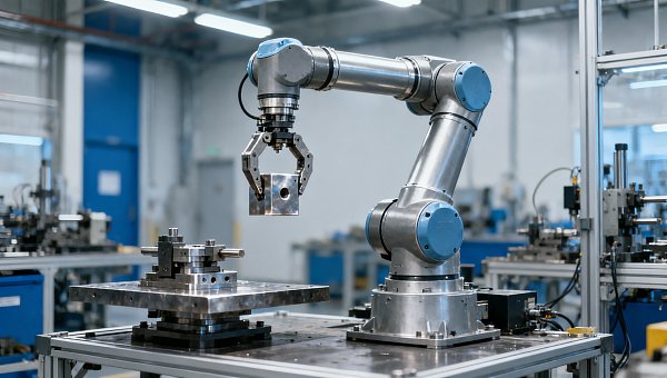
In robotics and automation cells, machine vision 3D measurement systems also support guidance and verification together. That sounds efficient, yet guidance-grade data is not always measurement-grade data.
When one system is expected to locate, orient, and certify dimensions, the validation burden rises sharply. TSV-style benchmarking logic is useful here because it separates sensing capability from usable engineering confidence.
Different sectors ask different questions from the same technology
Across general industry, machine vision 3D measurement systems serve very different decision points. The useful comparison is not industry by industry in name only, but by what the process must prevent.
In precision machining, the system often screens tool wear signatures before scrap multiplies. In sheet metal, it catches forming drift. In electronics assembly, it checks coplanarity and connector height.
In UAV and aerospace structures, the concern may be contour conformity, bond line geometry, or lightweight part distortion. Here, tolerance failure can affect aerodynamic fit and fatigue behavior.
In sensors and edge AI environments, data handling becomes part of the fit question. Machine vision 3D measurement systems generate useful geometry only if throughput, storage, and edge processing keep pace.
That is why broad claims about “high precision” rarely help. What matters is whether the system can resolve the exact failure mode that the production step actually creates.
Common mistakes happen before installation, not after
One frequent mistake is treating similar parts as identical inspection cases. A matte molded cover and a glossy molded cover may share geometry, yet require very different lighting and exposure behavior.
Another mistake is choosing machine vision 3D measurement systems only by headline microns. If fixtures shift, ambient temperature drifts, or the part arrives tilted, that number may never appear on the line.
It is also common to underestimate implementation cost. Calibration routines, enclosure design, maintenance cleaning, and operator recovery after false alarms all affect total system value.
Long-term use introduces another layer. Replacement parts, software support, algorithm updates, and compatibility with MES or PLC infrastructure can matter as much as first-pass measurement results.
- Do not validate only on ideal samples.
- Do not assume offline accuracy transfers inline.
- Do not ignore environmental shielding and cleaning access.
- Do not mix guidance tolerances with certification tolerances.
How to match machine vision 3D measurement systems to real requirements
A practical selection path begins with three numbers: target tolerance, available cycle time, and allowable false decision rate. Everything else follows from those constraints.
Then define the failure mode. Is the process trying to catch warpage, missing height, gap variation, profile drift, or assembly misfit? Machine vision 3D measurement systems are strongest when that target is explicit.
After that, map the environment. Check reflectivity, ambient light, vibration, part temperature, and indexing repeatability. These factors often decide sensor family more than catalog specifications do.
It also helps to separate inline screening from traceable dimensional release. Many operations need both, but not from the same station. A hybrid architecture is often more robust than forcing one tool to do everything.
The next step is straightforward: define several representative parts, run measurement trials at real line speed, compare repeatability against tolerance bands, and document where the system loses confidence.
That kind of disciplined evaluation reflects the TSV mindset. Engineering truth comes from measured fit, not from adjectives. For machine vision 3D measurement systems, that is the difference between adoption and dependable control.
Search News
Hot Articles
- Carbon Fiber StructuresHow to Specify Aerospace Carbon Fiber Assemblies for Lightweight, Load-Bearing PartsJul 11, 2026
- Machine VisionXiaomi, Alibaba DAMO Academy Drive Open-Source Robotics Model Ecosystem, Lowering Algorithm Development Barriers for Overseas SMEs Adopting Chinese Robotics SolutionsMar 30, 2026
- Cobots & ArmsShanxi 'AI+' Conference Showcases Embodied Intelligence with Multinational Buyer Engagement: Key Industry ImplicationsMar 30, 2026
Popular Tags
Recommended News
 Jul 11, 2026How to Specify Aerospace Carbon Fiber Assemblies for Lightweight, Load-Bearing PartsAerospace carbon fiber assemblies: learn how to specify laminate design, load data, joining methods, and inspection controls for lighter, reliable load-bearing aerospace parts.Elena Rostova (UAV Systems Researcher)
 Mar 30, 2026Xiaomi, Alibaba DAMO Academy Drive Open-Source Robotics Model Ecosystem, Lowering Algorithm Development Barriers for Overseas SMEs Adopting Chinese Robotics SolutionsXiaomi & Alibaba DAMO Academy's open-source robotics models lower algorithm barriers for global SMEs. Boost efficiency in manufacturing, logistics & smart retail with ROS 2 compatible solutions.TSV Data Lab
 Mar 30, 2026Shanxi 'AI+' Conference Showcases Embodied Intelligence with Multinational Buyer Engagement: Key Industry ImplicationsShanxi 'AI+' Conference highlights embodied intelligence with Tesla, Ubtech & Jiantao showcasing multimodal robotics. 40+ global buyers validated tech on-site, creating new B2B channels for industrial automation & AI solutions.Chen Wei (Automation Lead Engineer)
 Mar 30, 2026Zhongguancun Unveils 6G Integrated Sensing-Computing-Intelligence Platform to Empower Embodied Robots for Global Industrial ApplicationsZhongguancun's new 6G platform revolutionizes industrial robotics with <10ms latency, empowering global automotive, logistics & port automation. Discover how this tech boosts China's smart manufacturing exports.TSV Data Lab
 Mar 30, 2026Mech-Mind Tianjin Embodied Intelligence R&D and Production Base Goes Live, Cutting Delivery Time by 20%–30% for Global Customized AMR+Vision SolutionsMech-Mind's Tianjin AMR+Vision production base cuts delivery time by 20%-30% for欧美 & Latin American markets. Discover how this PLd-certified facility accelerates customized robotics solutions for smart manufacturing and logistics.Chen Wei (Automation Lead Engineer)
 Mar 30, 2026Boao Forum Reveals 'Co-evolution of Big and Small Brains' Trend in Humanoid Robots, China's Embodied Intelligence Accelerates Adaptation to Overseas Manufacturing Service ScenariosDiscover how China's humanoid robots, featuring 'Co-evolution of Big and Small Brains,' are revolutionizing global manufacturing. Learn about Embodied Tian Gong 3.0's ISO compliance and overseas deployment at Boao Forum 2026.Chen Wei (Automation Lead Engineer)
 Mar 30, 2026China Railway Industrial Secures Patent for Embodied Robotics in Material Handling, Boosting High-Precision Delivery Capabilities for Overseas Infrastructure and Manufacturing ProjectsChina Railway Industrial's new patent for embodied robotics in material handling boosts high-precision delivery for global infrastructure & manufacturing. Discover how this innovation enhances logistics accuracy in automotive, rail transit & EPC projects.Chen Wei (Automation Lead Engineer)
 Oct 22, 2026KUKA Showcases Physical AI and iiQKA.AI Vision at NVIDIA GTC BerlinExplore KUKA’s Physical AI showcase at NVIDIA GTC Berlin and discover how iiQKA.AI Vision aims to simplify robotic vision integration and improve 2D and 3D scene recognition.TSV Data Lab
 Oct 22, 2026Robotic Machining of Advanced Composites: What Tolerances Are Achievable?Explore advanced materials machining robotics: discover what drives achievable composite tolerances and how to validate accuracy before investing in your next machining system.Dr. Marcus Vance
 Oct 21, 2026China’s Industrial Robot Exports Near RMB 10 Billion in First Nine Months of 2026China’s industrial robot exports neared RMB 10 billion in January–September 2026, with value rising faster than volume. Explore the data and what it could mean for suppliers.Chen Wei (Automation Lead Engineer)
 Oct 21, 2026Low-Latency Industrial Data Processing: Pricing and Key Cost DriversExplore industrial data latency price drivers, from edge hardware to integration and support. Learn how to compare quotes, verify performance, and avoid unnecessary costs.TSV Data Lab
 Oct 20, 2026KUKA Launches iiQKA.AI Vision to Simplify Industrial Image ProcessingKUKA iiQKA.AI Vision simplifies industrial image processing with controller-based 2D and 3D vision. Explore drag-and-drop setup for vision-guided automation.TSV Data Lab
 Oct 20, 2026Smart Industrial Edge Devices: Key Criteria for Legacy PLC IntegrationChoose smart industrial edge devices for legacy PLC integration. Discover key criteria for compatibility, data quality, security, and reliable collection without disrupting control.TSV Data Lab
 Oct 19, 2026Choosing a Radar Sensor by Application: Range, Resolution, and Field of ViewSimplify radar sensor application based product selection. Compare range, resolution, and field of view to avoid blind spots and choose with confidence. Explore the guide.TSV Data Lab
 Oct 18, 2026Comparing Material Options for Procurement: Specs, Costs, and Supply RisksExplore procurement oriented technical content on material options, specs, costs, and supply risks. Compare alternatives to cut hidden expenses and make confident sourcing decisions.Dr. Marcus Vance
 Oct 17, 20265-Axis CNC Positioning Accuracy: How to Interpret ISO 230-2 Test ResultsAssess 5 axis CNC machining positioning accuracy with ISO 230-2. Learn to interpret repeatability, reversal error, and test conditions to compare suppliers and make confident acceptance decisions.Dr. Marcus Vance
 Oct 16, 2026Choosing a Rugged Edge AI Box Supplier: Thermal Tests and Lifecycle SupportChoose a rugged edge AI box supplier with proven thermal performance and reliable lifecycle support. Discover the tests and commitments to verify before you buy.TSV Data Lab
 Oct 15, 2026R&D Cost Reduction Services: How to Evaluate Fees, Savings, and ROIEvaluate R&D cost reduction services with confidence. Compare fees, verify savings, and calculate ROI without compromising performance. Discover how to choose a provider that delivers real value.Chen Wei (Automation Lead Engineer)
 Oct 21, 2026How Should You Balance Cobot Payload Against Reach?Explore cobot payload versus reach to choose the right robot. Learn how tooling, load limits, workspace, and cycle time affect performance—and avoid costly selection mistakes.Chen Wei (Automation Lead Engineer)
 Oct 20, 2026How Do You Measure Industrial IoT Gateway Latency Under Load?Measure industrial IoT gateway latency under load with reliable timestamps, realistic traffic, and tail-latency analysis. Discover how to expose bottlenecks and choose the right gateway.TSV Data Lab
 Oct 19, 2026How Do You Verify That Precision Machined Parts Meet Tolerances?Master precision machining tolerance verification with the right tools, datum setups, and acceptance rules. Learn how to validate parts confidently and reduce costly inspection errors.Dr. Marcus Vance
 Oct 18, 2026What Should an AS9100 Machining Supplier Checklist Include?Build an AS9100 machining supplier checklist that verifies capability, traceability, inspection, and outsourced processes. Discover what to check before approving your next aerospace supplier.Dr. Marcus Vance
 Oct 17, 2026How Should You Interpret Industrial Robot Repeatability Specs?Decode industrial robot repeatability specifications, understand ISO 9283 test conditions, and avoid costly selection mistakes. Learn how to verify performance for your process.Chen Wei (Automation Lead Engineer)
 Oct 16, 2026How Can You Fairly Compare MTBF Across Industrial Servo Motors?Make a fair industrial servo motor MTBF comparison with matched operating profiles, failure criteria, and confidence bounds. Discover how to assess reliability beyond advertised numbers.Chen Wei (Automation Lead Engineer)