Robotic Machining of Advanced Composites: What Tolerances Are Achievable?
Publication Date
author
Robotic machining of advanced composites has no universal achievable tolerance. A defensible tolerance belongs to a validated combination of robot, spindle, tooling, material, fixture, toolpath, and measurement method. Broad trimming tolerances are less demanding than tight hole location or diameter control; success on an external contour does not establish capability for precision fastening features.
A drawing requirement of ±0.5 mm and one of ±0.05 mm create substantially different process demands. These are illustrative specification targets, not claimed robot capabilities. The tighter requirement leaves much less room for cutting deflection, datum error, thermal drift, and measurement uncertainty. Robot repeatability alone cannot establish whether either requirement is achievable.
Define the tolerance before judging the robot
“Machining accuracy” often combines measurements that need separate acceptance criteria. Contour deviation, hole diameter, hole position, and edge damage describe different outcomes. A hole can meet its diameter tolerance while its axis is misplaced. A trimmed edge can follow the nominal profile while carrying unacceptable delamination beneath the surface.
The drawing also needs to define whether the composite is measured restrained or released from its fixture. Thin laminates and curved panels change shape under clamping. A contour machined correctly in the restrained condition can move outside its tolerance after release, even when the robot followed its commanded trajectory accurately.
For advanced materials machining robotics, a useful capability statement therefore identifies the feature, laminate, working envelope, and inspection basis. A single accuracy number without those conditions has limited technical value.
Repeatability does not include the cutting load
Robot repeatability describes how consistently a robot returns to a pose under defined test conditions. Absolute accuracy describes how closely the attained pose matches its commanded location. Neither measurement, by itself, describes the tool center point moving through a composite under changing cutting forces.
During machining, compliance exists throughout the chain: robot joints, mounting structure, spindle bracket, toolholder, cutter, fixture, and laminate. A useful first approximation is deflection ≈ cutting force / effective stiffness. Effective stiffness varies with direction and robot posture, so the same cutting force produces different displacement at different locations.
This explains why a straight cut near a favorable arm posture can pass inspection while a distant corner fails. Approaching an extended posture changes stiffness; rotating the wrist changes how the cutting force loads the structure. A constant programmed feed does not produce constant dimensional error across the envelope.
Calibration reduces systematic positioning error. Compensation can also correct repeatable deviations mapped under representative conditions. Neither guarantees removal of deflection that changes with tool wear, fiber orientation, local thickness, or engagement. A compensation map established with a fresh cutter and lightly loaded cut needs validation before being applied to a more demanding operation.
External metrology adds another distinction. Measuring the robot or spindle pose does not necessarily measure the actual cutting edge. Tool bending, spindle growth, and workpiece movement remain downstream of some tracking arrangements. Feedback claims should identify what is measured, how quickly corrections occur, and which errors remain outside the measurement loop.
Trimming and precision holes need different evidence
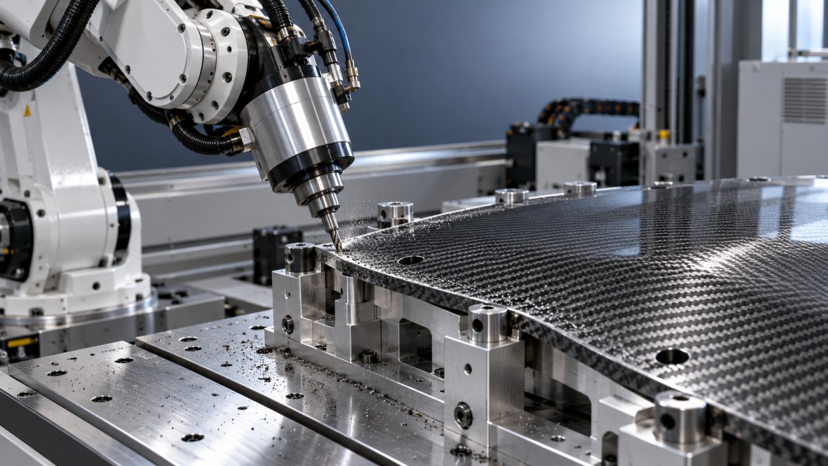
Composite trimming is a strong candidate for robotic machining when access, part size, and contour flexibility matter. Its limiting errors frequently involve lateral tool displacement, vibration, local panel movement, and changing engagement. A light finishing pass reduces cutting load, provided sufficient stock remains and the cutter engages consistently.
However, repeated spring passes are not a reliable cure for every profile error. A flexible panel can move away from the cutter and return after contact. Additional passes can then rub the matrix or remove material unevenly without resolving the support problem. Comparing restrained and released measurements helps distinguish structural movement from path error.
Precision holes impose additional constraints. Drilling produces axial thrust that can damage unsupported exit plies. Conventional drilling, orbital milling, and helical interpolation create different force patterns and tool engagement. Their suitability depends on laminate thickness, available backing, required diameter, and whether the operation cuts a composite alone or a composite-metal stack.
Hole diameter and hole position require separate demonstrations. A well-controlled cutting tool can produce an acceptable diameter at an incorrectly located center. Conversely, accurate positioning does not prevent an oversized or lobed hole caused by runout, vibration, or tool deflection. Axis orientation also matters through a thick laminate because a small angular error produces a larger exit-location error.
Where a hole requirement exceeds the demonstrated capability of the robot-mounted spindle, local mechanical guidance or a separate precision finishing operation changes the process architecture. Any resulting capability belongs to that complete arrangement. It should not be attributed to the robot alone.
The laminate changes the process window
Carbon-fiber and glass-fiber composites are abrasive, direction-dependent materials. As a cutter follows a curved boundary, its direction relative to the fibers changes even when feed and spindle speed remain constant. Cutting forces, fiber fracture, and surface condition consequently vary along the same contour.
Layup matters beyond the material label. Woven and unidirectional reinforcement, outer-ply orientation, resin system, thickness, and sandwich construction affect machining behavior. A process qualified on a flat solid laminate does not automatically cover a thin facesheet supported by a lightweight core. Near a free edge, reduced support can dominate the result.
Tool wear can degrade edge integrity before dimensional drift becomes obvious. Fiber breakout, fuzzy edges, matrix smearing, or increasing cutting force can therefore provide useful wear signals. Tool-life limits based only on elapsed machining time miss differences in engagement, material abrasiveness, and actual cutting distance.
Heat introduces a separate failure mechanism. Rubbing from a worn edge or unsuitable cutting conditions can raise local temperature and affect the resin. A smooth-looking surface does not prove that thermal damage is absent. Where surface integrity is functionally significant, qualification needs a defined assessment method beyond visual appearance.
Dust extraction and cooling arrangements belong in the validated setup. Extraction hardware can restrict access, alter hose forces, or interfere with close support. If cooling is used, compatibility with the material system and subsequent bonding or finishing operations must be established.
Fixturing determines which geometry is being made
A fixture must establish datums and resist machining forces without distorting the part beyond its defined restraint condition. Increasing clamping force is not automatically beneficial. Vacuum support can pull a compliant laminate toward the fixture surface, while concentrated clamps can introduce local bending.
Support placement near the cut often matters more than total holding force. An unsupported flange can vibrate despite secure clamping elsewhere. Backing near a hole exit reduces unsupported bending of the final plies, although backing contact and condition must remain consistent through the production run.
Incoming part variation also needs a machining strategy. Registering a molded component to nominal CAD does not guarantee equal stock everywhere. Global best-fit alignment can distribute deviations across the surface while shifting functional features away from their required datums.
If a recess requires controlled remaining thickness, referencing only the outer surface is insufficient when laminate thickness varies. The process needs suitable thickness information or another validated means of establishing the opposite boundary. Accurate robot motion cannot recover information absent from the setup.
Turn an accuracy claim into measurable capability
A credible demonstration uses the intended material, representative geometry, production fixturing, and relevant robot postures. A single coupon cut near the center of the workspace reveals little about a large component whose critical features occupy less favorable positions.
The evidence should connect observed variation to production conditions:
- Spatial coverage: include critical features at different arm reaches and cutting orientations, especially where force direction or support changes.
- Repeated setups are necessary to expose datum registration and loading variation. Repeated cuts without disturbing the fixture isolate only part of the process.
- Tool condition: compare results across the proposed usable tool life, including the edge-quality criteria that trigger replacement.
- Cold starts, sustained operation, and relevant ambient changes establish whether thermal behavior shifts the process mean.
Keep maximum observed deviation separate from statistical capability. A set of passing parts demonstrates those measured outcomes; it does not establish a guaranteed limit for future production. Capability indices require a stable process, adequate sampling, and a distribution model appropriate to the measured characteristic.
Signed contour deviation and diametral position error, for example, have different statistical behavior. Pooling unrelated features or robot postures can hide local failures behind an acceptable overall result. Report critical regions separately when their mechanics differ.
Measurement uncertainty also consumes decision margin. Probe access, part restraint during inspection, surface filtering, datum construction, and instrument uncertainty all affect the result. A measurement system suitable for broad trimming tolerances may be inadequate for a much tighter hole requirement. The acceptance rule should state how uncertainty is handled near the specification boundary.
Specify the acceptance boundary in the drawing and trial plan
A workable specification links geometry to its physical reference: named datums, restraint condition, inspection temperature where relevant, and feature-specific tolerances. Composite edge acceptance needs its own limits and measurement method. Terms such as “clean edge” or “no visible damage” leave lighting, magnification, and defect interpretation unresolved.
For a proposed tight-tolerance application, the trial should preserve the intended production sequence. Machining coupons separately, then extrapolating to a flexible assembled panel, omits the very compliance and registration errors that may control the outcome. Any secondary reaming, local probing, or adaptive correction must appear in the documented process.
The achievable tolerance is the range supported by that complete process under its defined operating conditions. When a trial fails, the deviation pattern guides the next change: posture-dependent offsets suggest stiffness or calibration issues; progressive drift points toward wear or temperature; movement after unclamping implicates restraint. The next trial should test that cause directly and retain the same functional acceptance criteria.
Search News
Hot Articles
- Carbon Fiber StructuresHow to Specify Aerospace Carbon Fiber Assemblies for Lightweight, Load-Bearing PartsJul 11, 2026
- Machine VisionXiaomi, Alibaba DAMO Academy Drive Open-Source Robotics Model Ecosystem, Lowering Algorithm Development Barriers for Overseas SMEs Adopting Chinese Robotics SolutionsMar 30, 2026
- Cobots & ArmsShanxi 'AI+' Conference Showcases Embodied Intelligence with Multinational Buyer Engagement: Key Industry ImplicationsMar 30, 2026
Popular Tags
Recommended News
 Jul 11, 2026How to Specify Aerospace Carbon Fiber Assemblies for Lightweight, Load-Bearing PartsAerospace carbon fiber assemblies: learn how to specify laminate design, load data, joining methods, and inspection controls for lighter, reliable load-bearing aerospace parts.Elena Rostova (UAV Systems Researcher)
 Mar 30, 2026Xiaomi, Alibaba DAMO Academy Drive Open-Source Robotics Model Ecosystem, Lowering Algorithm Development Barriers for Overseas SMEs Adopting Chinese Robotics SolutionsXiaomi & Alibaba DAMO Academy's open-source robotics models lower algorithm barriers for global SMEs. Boost efficiency in manufacturing, logistics & smart retail with ROS 2 compatible solutions.TSV Data Lab
 Mar 30, 2026Shanxi 'AI+' Conference Showcases Embodied Intelligence with Multinational Buyer Engagement: Key Industry ImplicationsShanxi 'AI+' Conference highlights embodied intelligence with Tesla, Ubtech & Jiantao showcasing multimodal robotics. 40+ global buyers validated tech on-site, creating new B2B channels for industrial automation & AI solutions.Chen Wei (Automation Lead Engineer)
 Mar 30, 2026Zhongguancun Unveils 6G Integrated Sensing-Computing-Intelligence Platform to Empower Embodied Robots for Global Industrial ApplicationsZhongguancun's new 6G platform revolutionizes industrial robotics with <10ms latency, empowering global automotive, logistics & port automation. Discover how this tech boosts China's smart manufacturing exports.TSV Data Lab
 Mar 30, 2026Mech-Mind Tianjin Embodied Intelligence R&D and Production Base Goes Live, Cutting Delivery Time by 20%–30% for Global Customized AMR+Vision SolutionsMech-Mind's Tianjin AMR+Vision production base cuts delivery time by 20%-30% for欧美 & Latin American markets. Discover how this PLd-certified facility accelerates customized robotics solutions for smart manufacturing and logistics.Chen Wei (Automation Lead Engineer)
 Mar 30, 2026Boao Forum Reveals 'Co-evolution of Big and Small Brains' Trend in Humanoid Robots, China's Embodied Intelligence Accelerates Adaptation to Overseas Manufacturing Service ScenariosDiscover how China's humanoid robots, featuring 'Co-evolution of Big and Small Brains,' are revolutionizing global manufacturing. Learn about Embodied Tian Gong 3.0's ISO compliance and overseas deployment at Boao Forum 2026.Chen Wei (Automation Lead Engineer)
 Mar 30, 2026China Railway Industrial Secures Patent for Embodied Robotics in Material Handling, Boosting High-Precision Delivery Capabilities for Overseas Infrastructure and Manufacturing ProjectsChina Railway Industrial's new patent for embodied robotics in material handling boosts high-precision delivery for global infrastructure & manufacturing. Discover how this innovation enhances logistics accuracy in automotive, rail transit & EPC projects.Chen Wei (Automation Lead Engineer)
 Oct 22, 2026Robotic Machining of Advanced Composites: What Tolerances Are Achievable?Explore advanced materials machining robotics: discover what drives achievable composite tolerances and how to validate accuracy before investing in your next machining system.Dr. Marcus Vance
 Oct 21, 2026China’s Industrial Robot Exports Near RMB 10 Billion in First Nine Months of 2026China’s industrial robot exports neared RMB 10 billion in January–September 2026, with value rising faster than volume. Explore the data and what it could mean for suppliers.Chen Wei (Automation Lead Engineer)
 Oct 21, 2026Low-Latency Industrial Data Processing: Pricing and Key Cost DriversExplore industrial data latency price drivers, from edge hardware to integration and support. Learn how to compare quotes, verify performance, and avoid unnecessary costs.TSV Data Lab
 Oct 20, 2026KUKA Launches iiQKA.AI Vision to Simplify Industrial Image ProcessingKUKA iiQKA.AI Vision simplifies industrial image processing with controller-based 2D and 3D vision. Explore drag-and-drop setup for vision-guided automation.TSV Data Lab
 Oct 20, 2026Smart Industrial Edge Devices: Key Criteria for Legacy PLC IntegrationChoose smart industrial edge devices for legacy PLC integration. Discover key criteria for compatibility, data quality, security, and reliable collection without disrupting control.TSV Data Lab
 Oct 19, 2026Choosing a Radar Sensor by Application: Range, Resolution, and Field of ViewSimplify radar sensor application based product selection. Compare range, resolution, and field of view to avoid blind spots and choose with confidence. Explore the guide.TSV Data Lab
 Oct 18, 2026Comparing Material Options for Procurement: Specs, Costs, and Supply RisksExplore procurement oriented technical content on material options, specs, costs, and supply risks. Compare alternatives to cut hidden expenses and make confident sourcing decisions.Dr. Marcus Vance
 Oct 17, 20265-Axis CNC Positioning Accuracy: How to Interpret ISO 230-2 Test ResultsAssess 5 axis CNC machining positioning accuracy with ISO 230-2. Learn to interpret repeatability, reversal error, and test conditions to compare suppliers and make confident acceptance decisions.Dr. Marcus Vance
 Oct 16, 2026Choosing a Rugged Edge AI Box Supplier: Thermal Tests and Lifecycle SupportChoose a rugged edge AI box supplier with proven thermal performance and reliable lifecycle support. Discover the tests and commitments to verify before you buy.TSV Data Lab
 Oct 15, 2026R&D Cost Reduction Services: How to Evaluate Fees, Savings, and ROIEvaluate R&D cost reduction services with confidence. Compare fees, verify savings, and calculate ROI without compromising performance. Discover how to choose a provider that delivers real value.Chen Wei (Automation Lead Engineer)
 Oct 21, 2026How Should You Balance Cobot Payload Against Reach?Explore cobot payload versus reach to choose the right robot. Learn how tooling, load limits, workspace, and cycle time affect performance—and avoid costly selection mistakes.Chen Wei (Automation Lead Engineer)
 Oct 20, 2026How Do You Measure Industrial IoT Gateway Latency Under Load?Measure industrial IoT gateway latency under load with reliable timestamps, realistic traffic, and tail-latency analysis. Discover how to expose bottlenecks and choose the right gateway.TSV Data Lab
 Oct 19, 2026How Do You Verify That Precision Machined Parts Meet Tolerances?Master precision machining tolerance verification with the right tools, datum setups, and acceptance rules. Learn how to validate parts confidently and reduce costly inspection errors.Dr. Marcus Vance
 Oct 18, 2026What Should an AS9100 Machining Supplier Checklist Include?Build an AS9100 machining supplier checklist that verifies capability, traceability, inspection, and outsourced processes. Discover what to check before approving your next aerospace supplier.Dr. Marcus Vance
 Oct 17, 2026How Should You Interpret Industrial Robot Repeatability Specs?Decode industrial robot repeatability specifications, understand ISO 9283 test conditions, and avoid costly selection mistakes. Learn how to verify performance for your process.Chen Wei (Automation Lead Engineer)
 Oct 16, 2026How Can You Fairly Compare MTBF Across Industrial Servo Motors?Make a fair industrial servo motor MTBF comparison with matched operating profiles, failure criteria, and confidence bounds. Discover how to assess reliability beyond advertised numbers.Chen Wei (Automation Lead Engineer)
 Oct 15, 2026How Should You Compare TechStat Vanguard 5-Axis CNC Tolerances?TechStat Vanguard 5-axis CNC tolerance comparison: learn how to verify part accuracy, assess inspection evidence, and choose suppliers that reliably meet your drawing requirements.Dr. Marcus Vance