
Why Servo Drive Accuracy Drops Under Load Spikes
Publication Date
author
When a motion system performs flawlessly at nominal load but loses position during sudden torque surges, the root cause is rarely random. For after-sales maintenance teams, understanding why servo drive accuracy drops under load spikes is essential to faster diagnostics and fewer repeat failures. This article explains the hidden interactions among inertia mismatch, current loop response, encoder feedback, and mechanical transmission behavior—insights every team and high precision servo drive supplier should evaluate before accuracy losses become costly downtime.
Servo Drive Accuracy Under Load Spikes: Core Definition and Failure Logic
Servo drive accuracy refers to how precisely a motion axis follows commanded position, speed, and torque under real operating conditions. In a stable state, most systems can meet nominal specifications. The challenge appears during load spikes: abrupt increases in resisting torque caused by impact cutting, sudden acceleration, product jams, tool engagement, or intermittent friction. At that moment, the control loop must react faster than the disturbance grows. If it cannot, transient following error increases and visible accuracy loss appears.
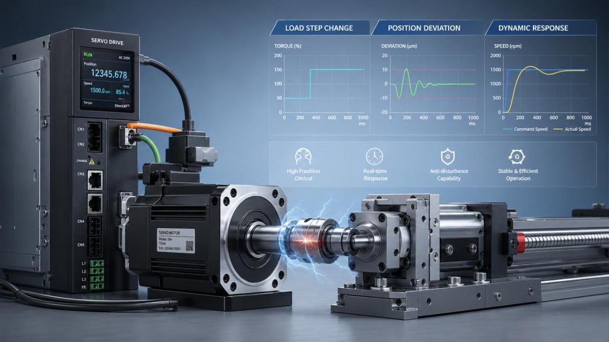
A high precision servo drive supplier typically evaluates accuracy not only by static repeatability, but also by dynamic error during disturbance events. That distinction matters because many field failures are not caused by insufficient peak power alone. They result from a chain reaction involving motor sizing, drive tuning, bus voltage stability, encoder resolution, and mechanical elasticity. Once the disturbance exceeds the system’s controllable window, the axis may overshoot, lag, oscillate, or trigger protection logic.
In practical terms, load spikes expose the difference between catalog performance and installed performance. A specification sheet may show excellent settling time under test conditions, yet the installed axis can still lose accuracy if reflected inertia is too high, couplings wind up under torque, or the encoder signal is degraded by electrical noise. This is why a high precision servo drive supplier should be judged by disturbance rejection data, tuning tools, and integration guidance rather than by headline torque numbers alone.
Current Industry Signals That Explain Growing Attention
Across automation, precision machining, packaging, material handling, and aerospace subassembly, systems are being pushed toward shorter cycle times and higher throughput. These demands increase the frequency and severity of dynamic load transitions. As a result, servo accuracy during torque spikes has become a practical reliability issue rather than a niche tuning topic.
These signals explain why the selection of a high precision servo drive supplier increasingly depends on evidence around dynamic stability, encoder robustness, and application-specific tuning support. In modern equipment, accuracy is no longer a single component property. It is a system behavior shaped by software, power electronics, mechanical design, and disturbance conditions.
What Causes Accuracy to Drop During Sudden Load Increases
Several technical mechanisms usually interact at the same time. Understanding each one helps isolate the actual failure path instead of replacing parts blindly.
1. Inertia mismatch reduces disturbance rejection
If the reflected load inertia is much larger than motor inertia, the axis becomes harder to control during sudden torque demand. The motor must work through a larger stored mechanical energy barrier, so commanded correction arrives too slowly. This creates lag and may force lower gain settings to avoid oscillation. A capable high precision servo drive supplier should provide clear inertia ratio guidelines and tuning support based on actual load profiles rather than idealized bench conditions.
2. Current loop saturation limits instant torque output
Servo drives rely on the current loop to generate electromagnetic torque. During a load spike, the required current can rise faster than the drive’s available peak current, bus voltage, or thermal limit allows. When saturation occurs, the controller cannot produce the corrective torque needed to hold the trajectory. The result is temporary position error, followed by delayed recovery or oscillation.
3. Encoder resolution and signal quality constrain correction accuracy
The servo drive can only correct what it can measure. Under shock load, low-resolution feedback, interpolation error, cable noise, grounding issues, or connector instability can blur the position signal. That means the drive sees motion later or less accurately than it should. For this reason, any high precision servo drive supplier focused on demanding applications should address not just encoder counts, but also shielding, protocol integrity, and noise immunity.
4. Mechanical transmission compliance hides real motion loss
Backlash, belt stretch, coupling torsion, gearbox wind-up, and bearing play all store and release energy during load spikes. The motor shaft may appear to respond correctly while the load side lags behind. In systems where the encoder is mounted on the motor rather than the load, this difference can be significant. The issue is often misread as a drive tuning fault when the true cause is mechanical elasticity or wear.
5. Poorly tuned velocity and position loops amplify transients
Conservative tuning may be stable at nominal load but too slow during a spike. Aggressive tuning may react quickly yet excite resonance. The best result depends on loop bandwidth, notch filters, feedforward, jerk limits, and realistic disturbance testing. This is one reason the technical depth of a high precision servo drive supplier matters long after installation.
Operational Value of Understanding the Failure Pattern
Identifying why servo drive accuracy drops under load spikes has direct business value. It shortens troubleshooting time, prevents repeated field interventions, and helps separate electrical, control, and mechanical causes. More importantly, it avoids the costly assumption that a larger motor automatically solves dynamic accuracy problems.
- Reduces unnecessary replacement of drives, encoders, and motors when the root issue is transmission compliance.
- Improves machine uptime by targeting disturbance sources instead of symptoms.
- Supports more accurate supplier comparison by focusing on peak response, loop tools, and feedback robustness.
- Protects process quality where short transient errors produce dimensional defects or unstable motion paths.
For complex equipment, the most reliable path is a joint review of load profile, axis mechanics, drive logs, and feedback quality. A high precision servo drive supplier that can interpret oscilloscope traces, following error curves, and torque utilization history brings far more value than one offering only catalog substitutions.
Typical Scenarios Where Load Spikes Cause Servo Accuracy Loss
Not every axis is equally exposed. The following examples show where dynamic disturbances most often translate into visible accuracy problems.
These scenarios show why choosing a high precision servo drive supplier must involve application context. An axis exposed to cutting shock behaves very differently from one handling smooth indexing, even if their rated torque looks similar on paper.
Practical Diagnostic and Mitigation Guidance
A disciplined troubleshooting sequence prevents guesswork and speeds root-cause isolation. The following steps are practical in most field situations:
- Capture the event: Review drive logs for following error, actual current, bus voltage, and alarm timing during the spike.
- Compare commanded and actual motion: Look for lag, rebound, or oscillation patterns that indicate loop or compliance issues.
- Check reflected inertia and load changes: Validate whether the installed mechanics still match original tuning assumptions.
- Inspect transmission elements: Couplings, belts, gearboxes, and bearings should be checked for backlash, looseness, or torsional fatigue.
- Verify encoder and cabling integrity: Noise, grounding, or connector wear can mimic control instability.
- Retune with real disturbance conditions: Adjust gain, feedforward, filters, and jerk limits based on measured load spikes, not idle tests.
Where recurring spikes are unavoidable, mitigation may include a higher bus voltage margin, larger peak current capacity, dual-loop feedback, stiffer couplings, or revised motion profiles. A qualified high precision servo drive supplier should be able to recommend which change addresses the real bottleneck instead of oversizing every component.
Technical Next Steps for More Stable Precision Motion
Servo accuracy loss under load spikes is rarely the fault of one isolated part. It is usually the visible outcome of limited torque response, incomplete feedback fidelity, or hidden mechanical compliance. The most effective response is to evaluate the full motion chain with data: disturbance magnitude, current reserve, loop response, encoder quality, and load-side rigidity.
For any system showing intermittent position loss, start by documenting the exact operating moment when the spike occurs and correlate it with drive diagnostics. Then compare those findings against the tuning limits, inertia assumptions, and transmission condition. If the evidence points to inadequate dynamic reserve, engage a high precision servo drive supplier that can provide application-level analysis, not just a replacement part number. That approach turns recurring accuracy loss into a measurable engineering problem—and a solvable one.
Search News
Hot Articles
- Carbon Fiber StructuresHow to Specify Aerospace Carbon Fiber Assemblies for Lightweight, Load-Bearing PartsJul 11, 2026
- Machine VisionXiaomi, Alibaba DAMO Academy Drive Open-Source Robotics Model Ecosystem, Lowering Algorithm Development Barriers for Overseas SMEs Adopting Chinese Robotics SolutionsMar 30, 2026
- Cobots & ArmsShanxi 'AI+' Conference Showcases Embodied Intelligence with Multinational Buyer Engagement: Key Industry ImplicationsMar 30, 2026
Popular Tags
Recommended News
 Jul 11, 2026How to Specify Aerospace Carbon Fiber Assemblies for Lightweight, Load-Bearing PartsAerospace carbon fiber assemblies: learn how to specify laminate design, load data, joining methods, and inspection controls for lighter, reliable load-bearing aerospace parts.Elena Rostova (UAV Systems Researcher)
 Mar 30, 2026Xiaomi, Alibaba DAMO Academy Drive Open-Source Robotics Model Ecosystem, Lowering Algorithm Development Barriers for Overseas SMEs Adopting Chinese Robotics SolutionsXiaomi & Alibaba DAMO Academy's open-source robotics models lower algorithm barriers for global SMEs. Boost efficiency in manufacturing, logistics & smart retail with ROS 2 compatible solutions.TSV Data Lab
 Mar 30, 2026Shanxi 'AI+' Conference Showcases Embodied Intelligence with Multinational Buyer Engagement: Key Industry ImplicationsShanxi 'AI+' Conference highlights embodied intelligence with Tesla, Ubtech & Jiantao showcasing multimodal robotics. 40+ global buyers validated tech on-site, creating new B2B channels for industrial automation & AI solutions.Chen Wei (Automation Lead Engineer)
 Mar 30, 2026Zhongguancun Unveils 6G Integrated Sensing-Computing-Intelligence Platform to Empower Embodied Robots for Global Industrial ApplicationsZhongguancun's new 6G platform revolutionizes industrial robotics with <10ms latency, empowering global automotive, logistics & port automation. Discover how this tech boosts China's smart manufacturing exports.TSV Data Lab
 Mar 30, 2026Mech-Mind Tianjin Embodied Intelligence R&D and Production Base Goes Live, Cutting Delivery Time by 20%–30% for Global Customized AMR+Vision SolutionsMech-Mind's Tianjin AMR+Vision production base cuts delivery time by 20%-30% for欧美 & Latin American markets. Discover how this PLd-certified facility accelerates customized robotics solutions for smart manufacturing and logistics.Chen Wei (Automation Lead Engineer)
 Mar 30, 2026Boao Forum Reveals 'Co-evolution of Big and Small Brains' Trend in Humanoid Robots, China's Embodied Intelligence Accelerates Adaptation to Overseas Manufacturing Service ScenariosDiscover how China's humanoid robots, featuring 'Co-evolution of Big and Small Brains,' are revolutionizing global manufacturing. Learn about Embodied Tian Gong 3.0's ISO compliance and overseas deployment at Boao Forum 2026.Chen Wei (Automation Lead Engineer)
 Mar 30, 2026China Railway Industrial Secures Patent for Embodied Robotics in Material Handling, Boosting High-Precision Delivery Capabilities for Overseas Infrastructure and Manufacturing ProjectsChina Railway Industrial's new patent for embodied robotics in material handling boosts high-precision delivery for global infrastructure & manufacturing. Discover how this innovation enhances logistics accuracy in automotive, rail transit & EPC projects.Chen Wei (Automation Lead Engineer)
 Sep 28, 2026Spindle Runout Measurement in Germany: DIN Standards, Methods, and Acceptance LimitsSpindle runout measurement Germany: explore DIN standards, proven methods, acceptance limits, and audit-ready practices for reliable machining quality.Dr. Marcus Vance
 Sep 27, 2026How to Select Wall-Mount Edge Devices for Space-Constrained Factory NetworksWall mount edge devices for space-constrained factories: evaluate workload, thermal design, power resilience, cable access, and network reliability for smarter deployments.TSV Data Lab
 Sep 26, 2026Machining Tolerance Analysis: How to Set Limits That Meet Function and Cost TargetsMachining tolerance analysis: learn how to set functional limits, control tolerance stacks, reduce inspection risk, and balance precision with production cost.Dr. Marcus Vance
 Sep 25, 2026How to Evaluate an Industrial Infrastructure Data Platform for Multi-Site OperationsIndustrial infrastructure data platform evaluation guide for multi-site operations: compare data quality, edge resilience, interoperability, governance, and scalable proof-of-value criteria.Victor Lin (Chief Software Architect)
 Sep 24, 2026How to Select Machine Vision Optics for Accurate Inspection at Different Working DistancesMachine vision optics selection guide for accurate inspection at every working distance. Compare FOV, pixel scale, DOF, distortion, lighting, and telecentric options.TSV Data Lab
 Sep 23, 2026How to Evaluate a Machine Vision System Integrator for High-Speed Inspection LinesChoose a machine vision system integrator with proven expertise in high-speed inspection, reliable reject timing, robust optics, and measurable acceptance criteria.TSV Data Lab
 Sep 28, 2026When is a SCADA API the right choice for connecting plant systems?SCADA API guide: learn when governed plant data integration improves traceability, security, and scalability—without compromising real-time control.Victor Lin (Chief Software Architect)
 Sep 27, 2026How SCADA data integration improves traceability across production linesSCADA data integration connects production-line data to improve traceability, accelerate quality investigations, and strengthen safety decisions.Victor Lin (Chief Software Architect)
 Sep 26, 2026What to define before starting SCADA integration planningSCADA integration planning starts with clear scope, control boundaries, data models, cybersecurity, and testing. Discover the definitions that reduce risk and costly rework.Victor Lin (Chief Software Architect)
 Sep 25, 2026How a smart factory with Industrial IoT reduces production blind spotsDiscover how a smart factory with Industrial IoT turns real-time machine, quality, and workflow data into actionable insights that reduce production blind spots and delivery risks.Victor Lin (Chief Software Architect)
 Sep 24, 2026When does Industrial IoT make smart manufacturing easier to scale?Smart manufacturing Industrial IoT scales when trusted data, interoperable systems, and secure workflows turn connected assets into measurable gains.TSV Data Lab
 Sep 23, 2026What drives ultra-precision machining cost at 1-micron tolerance?Ultra precision machining cost per part at 1 micron tolerance depends on process, material, metrology, and yield. Learn how to compare quotes confidently.Dr. Marcus Vance
 Sep 22, 2026Drone Engine-T550CC Applications: Build the UAV Power System Around the MissionAn application guide for Drone Engine-T550CC integration, covering payload planning, airframe matching, cooling, fuel, vibration, test procedures, documentation, and service preparation.Elena Rostova (UAV Systems Researcher)
 Sep 22, 2026How to Evaluate Industrial Edge Computing Vendors for Factory DeploymentIndustrial edge computing vendor evaluation guide for factories: compare latency, protocol fit, reliability, security, and lifecycle support before deployment.TSV Data Lab
 Sep 21, 2026Drone Payload Integration: Matching Power, Data, and Center of Gravity for Reliable FlightsDrone payload integration made practical: balance power, data, center of gravity, and endurance to build safer, more reliable mission-ready flights.Elena Rostova (UAV Systems Researcher)
 Sep 20, 2026Autonomous Navigation Pricing: Cost Drivers and Budget Benchmarks for AMR ProjectsAutonomous navigation price explained: compare AMR cost drivers, software, sensors, integration, safety, and lifecycle budgets to build a scalable project plan.Chen Wei (Automation Lead Engineer)
 Sep 19, 2026How to Scope Automation Integration Services for Multi-System Factory ProjectsAutomation integration services: learn how to scope multi-system factory projects with clear workflows, interface contracts, safety boundaries, and acceptance criteria.Victor Lin (Chief Software Architect)























