
Robotic Arm for Injection Molding and Mold Open Time Limits
Publication Date
author
For operators chasing shorter cycles and more stable production, a robotic arm for injection molding is only as effective as the mold open time window it works within. When timing limits are too narrow, part handling, safety, and repeatability all suffer. This article examines the engineering logic behind mold open time constraints and how to align robot motion, machine signals, and process parameters for reliable, data-driven performance.
What does mold open time really mean for a robotic arm for injection molding?
In practical terms, mold open time is the usable interval between the mold reaching a safe open position and the next closing command. For a robotic arm for injection molding, this is not just a machine setting. It is the full operational window for entry, part grip, extraction, confirmation, exit, and safe clearance. If any one of those steps exceeds the available time, cycle instability begins immediately.
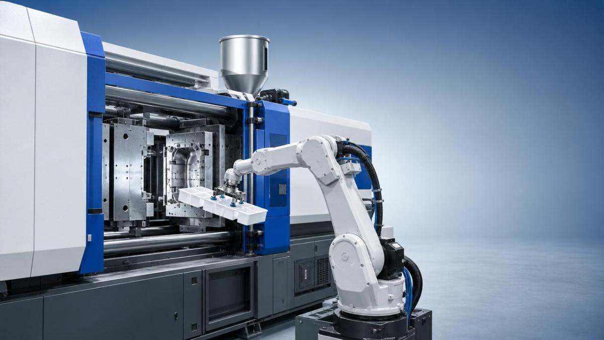
Many production issues come from treating mold open time as a single number instead of a sequence of time slices. The true engineering calculation includes mold full-open signal delay, robot response latency, axis acceleration time, end-of-arm tooling settling time, vacuum or gripper confirmation, and machine interlock margin. In a high-speed cell, even a 0.2 second mismatch can create part drops, deformed components, or emergency stops.
This is why a robotic arm for injection molding must be evaluated as part of the whole molding system rather than as a standalone automation add-on. TSV’s engineering-first view is simple: timing parameters must be mapped to machine reality. The robot must fit the window, and the window must reflect actual mold travel, cooling behavior, and part release consistency.
Why do mold open time limits become a bottleneck in real production?
The most common bottleneck is compressed cycle design. As injection molding lines are optimized for output, teams often reduce cooling time and mold open duration before confirming whether the robotic arm for injection molding can still perform safely. The result is a narrow extraction window that leaves no buffer for part variation, static adhesion, or robot path drift caused by wear.
Another bottleneck is signal sequencing. A robot may receive the mold-open confirmation slightly later than expected because of PLC logic, safety relay delay, or network communication lag. If the robot program was tuned under ideal conditions, this hidden delay cuts effective available time without appearing on the machine screen. Over thousands of cycles, small delays accumulate into stop-start instability.
Mechanical constraints also matter. Long-reach arms, heavier end-of-arm tooling, and multi-cavity part extraction increase inertia. Even when servo specifications look adequate on paper, actual acceleration and deceleration under load may reduce the margin inside the mold. In these cases, a robotic arm for injection molding may need a shorter stroke path, lighter tooling, or a revised pick orientation rather than a higher commanded speed.
- Shortened cooling time causing part sticking or soft deformation during pickup
- Late mold-open signal or early mold-close command reducing usable robot time
- Overly heavy EOAT slowing axis motion and increasing settling time
- Unoptimized robot path with unnecessary approach or retreat distance
- Safety margins set too tight for real-world process variation
How can you tell whether the robotic arm for injection molding is correctly matched to the cycle?
A good match is not defined by maximum speed alone. It is defined by repeatable execution inside the available time window with measurable safety margin. Start by breaking the cycle into event timestamps: mold fully open, robot start, entry complete, pickup confirmed, extraction clear, mold-close permit, and actual close. This event map reveals whether the robotic arm for injection molding has enough consistent clearance or is surviving on unstable micro-margins.
The next step is to compare nominal cycle time with worst-case cycle time. Nominal data may look acceptable, but mold contamination, part warpage, or pneumatic pressure fluctuation can stretch the extraction phase. If the worst-case window is too close to the close command threshold, the system is under-matched even if average performance appears fine.
A practical benchmark is to keep a defined safety reserve after the robot clears the mold area. The exact reserve depends on machine size, part geometry, and control architecture, but the engineering principle is universal: stable cells preserve clearance margin under variation. A robotic arm for injection molding that only works after frequent manual retuning is not properly matched.
What process and motion changes improve mold open time performance without increasing risk?
The first improvement is motion simplification. Many robot programs include conservative path points added during startup and never removed. Reducing unnecessary vertical lifts, lateral detours, or slow confirmation pauses can reclaim time without raising top speed. In many cells, path optimization gives more benefit than forcing a robotic arm for injection molding to run faster.
Second, reduce end-of-arm tooling mass and complexity. Smaller manifolds, shorter vacuum lines, fewer brackets, and balanced gripper layouts help servo axes accelerate and settle faster. Lower inertia also improves repeatability, which matters more than headline speed when mold open time is tight.
Third, review part release conditions inside the mold. If ejection is inconsistent, no robot tuning will permanently solve the issue. Check ejector timing, surface finish, venting, draft angle, static control, and part temperature at pickup. A robotic arm for injection molding works best when the molded part is ready for deterministic removal, not when the robot is compensating for poor release behavior.
Fourth, align signals at the controller level. Confirm that mold-open complete, robot enable, part takeout complete, and mold-close permit are all based on real mechanical states rather than optimistic timer assumptions. In advanced cells, timestamp logging from PLC and robot controller can expose hidden latency that operators cannot see during manual observation.
What are the most common mistakes when selecting a robotic arm for injection molding?
One common mistake is selecting by payload and reach only. Those values matter, but they do not reveal whether the robotic arm for injection molding can complete in-mold actions within a narrow open window. Acceleration profile, controller response, tooling integration, and allowable approach geometry are often more important than static catalog numbers.
Another mistake is assuming the shortest cycle is the best cycle. Excessively reducing mold open time may raise output in theory while increasing rejects, jams, and tooling wear in reality. If the robot is forced to operate with near-zero clearance, the cell becomes vulnerable to every small variation in material, temperature, and mold condition.
A third mistake is ignoring maintainability. A fast cell that cannot be cleaned, re-taught, or serviced efficiently often loses more time over a month than it saves per cycle. For this reason, a robotic arm for injection molding should be judged by total production stability, not by isolated best-case speed demonstrations.
- Do not size the robot only from brochure speed data
- Do not compress mold open time before verifying part release repeatability
- Do not overlook signal delays between machine, robot, and safety system
- Do not accept unstable manual tuning as normal operation
How should implementation decisions be made for long-term reliability?
Implementation should begin with measured baseline data, not assumptions. Record actual mold open duration, effective robot access time, extraction success rate, and clearance margin over a meaningful sample. Then compare that data against target throughput, reject tolerance, and maintenance limits. This provides a factual basis for deciding whether to change tooling, modify the robot path, or revise molding parameters.
It is also useful to define acceptance criteria before optimization starts. For example, a robotic arm for injection molding might need to achieve stable takeout across a specific number of cycles without intervention, maintain part handling integrity, and retain a minimum close-clearance reserve. These criteria prevent speed-focused tuning from undermining process control.
From a wider industrial perspective, the best-performing systems follow the same principle emphasized by data-driven engineering: measured tolerances beat marketing claims. Whether the application is consumer goods, medical molding, automotive components, or electronics housings, the right robotic arm for injection molding is the one that fits the real mold open time envelope with repeatable, traceable performance.
Quick FAQ reference
A robotic arm for injection molding delivers value when robot motion, mold timing, and part release physics are engineered as one system. If mold open time limits are already constraining output, the next step is not guesswork. Map the cycle, measure the latency, trim unnecessary motion, and verify buffer under real production variation. That approach produces the stable throughput, lower trial-and-error cost, and evidence-based optimization that advanced manufacturing depends on.
Search News
Hot Articles
- Carbon Fiber StructuresHow to Specify Aerospace Carbon Fiber Assemblies for Lightweight, Load-Bearing PartsJul 11, 2026
- Machine VisionXiaomi, Alibaba DAMO Academy Drive Open-Source Robotics Model Ecosystem, Lowering Algorithm Development Barriers for Overseas SMEs Adopting Chinese Robotics SolutionsMar 30, 2026
- Cobots & ArmsShanxi 'AI+' Conference Showcases Embodied Intelligence with Multinational Buyer Engagement: Key Industry ImplicationsMar 30, 2026
Popular Tags
Recommended News
 Jul 11, 2026How to Specify Aerospace Carbon Fiber Assemblies for Lightweight, Load-Bearing PartsAerospace carbon fiber assemblies: learn how to specify laminate design, load data, joining methods, and inspection controls for lighter, reliable load-bearing aerospace parts.Elena Rostova (UAV Systems Researcher)
 Mar 30, 2026Xiaomi, Alibaba DAMO Academy Drive Open-Source Robotics Model Ecosystem, Lowering Algorithm Development Barriers for Overseas SMEs Adopting Chinese Robotics SolutionsXiaomi & Alibaba DAMO Academy's open-source robotics models lower algorithm barriers for global SMEs. Boost efficiency in manufacturing, logistics & smart retail with ROS 2 compatible solutions.TSV Data Lab
 Mar 30, 2026Shanxi 'AI+' Conference Showcases Embodied Intelligence with Multinational Buyer Engagement: Key Industry ImplicationsShanxi 'AI+' Conference highlights embodied intelligence with Tesla, Ubtech & Jiantao showcasing multimodal robotics. 40+ global buyers validated tech on-site, creating new B2B channels for industrial automation & AI solutions.Chen Wei (Automation Lead Engineer)
 Mar 30, 2026Zhongguancun Unveils 6G Integrated Sensing-Computing-Intelligence Platform to Empower Embodied Robots for Global Industrial ApplicationsZhongguancun's new 6G platform revolutionizes industrial robotics with <10ms latency, empowering global automotive, logistics & port automation. Discover how this tech boosts China's smart manufacturing exports.TSV Data Lab
 Mar 30, 2026Mech-Mind Tianjin Embodied Intelligence R&D and Production Base Goes Live, Cutting Delivery Time by 20%–30% for Global Customized AMR+Vision SolutionsMech-Mind's Tianjin AMR+Vision production base cuts delivery time by 20%-30% for欧美 & Latin American markets. Discover how this PLd-certified facility accelerates customized robotics solutions for smart manufacturing and logistics.Chen Wei (Automation Lead Engineer)
 Mar 30, 2026Boao Forum Reveals 'Co-evolution of Big and Small Brains' Trend in Humanoid Robots, China's Embodied Intelligence Accelerates Adaptation to Overseas Manufacturing Service ScenariosDiscover how China's humanoid robots, featuring 'Co-evolution of Big and Small Brains,' are revolutionizing global manufacturing. Learn about Embodied Tian Gong 3.0's ISO compliance and overseas deployment at Boao Forum 2026.Chen Wei (Automation Lead Engineer)
 Mar 30, 2026China Railway Industrial Secures Patent for Embodied Robotics in Material Handling, Boosting High-Precision Delivery Capabilities for Overseas Infrastructure and Manufacturing ProjectsChina Railway Industrial's new patent for embodied robotics in material handling boosts high-precision delivery for global infrastructure & manufacturing. Discover how this innovation enhances logistics accuracy in automotive, rail transit & EPC projects.Chen Wei (Automation Lead Engineer)
 Sep 29, 2026ISO 9283 Repeatability: How to Evaluate Cobot Positioning PerformanceISO 9283 cobot repeatability explained: learn how payload, reach, approach direction, and test conditions affect positioning performance and cell capability.Chen Wei (Automation Lead Engineer)
 Sep 28, 2026Spindle Runout Measurement in Germany: DIN Standards, Methods, and Acceptance LimitsSpindle runout measurement Germany: explore DIN standards, proven methods, acceptance limits, and audit-ready practices for reliable machining quality.Dr. Marcus Vance
 Sep 27, 2026How to Select Wall-Mount Edge Devices for Space-Constrained Factory NetworksWall mount edge devices for space-constrained factories: evaluate workload, thermal design, power resilience, cable access, and network reliability for smarter deployments.TSV Data Lab
 Sep 26, 2026Machining Tolerance Analysis: How to Set Limits That Meet Function and Cost TargetsMachining tolerance analysis: learn how to set functional limits, control tolerance stacks, reduce inspection risk, and balance precision with production cost.Dr. Marcus Vance
 Sep 25, 2026How to Evaluate an Industrial Infrastructure Data Platform for Multi-Site OperationsIndustrial infrastructure data platform evaluation guide for multi-site operations: compare data quality, edge resilience, interoperability, governance, and scalable proof-of-value criteria.Victor Lin (Chief Software Architect)
 Sep 24, 2026How to Select Machine Vision Optics for Accurate Inspection at Different Working DistancesMachine vision optics selection guide for accurate inspection at every working distance. Compare FOV, pixel scale, DOF, distortion, lighting, and telecentric options.TSV Data Lab
 Sep 23, 2026How to Evaluate a Machine Vision System Integrator for High-Speed Inspection LinesChoose a machine vision system integrator with proven expertise in high-speed inspection, reliable reject timing, robust optics, and measurable acceptance criteria.TSV Data Lab
 Sep 28, 2026When is a SCADA API the right choice for connecting plant systems?SCADA API guide: learn when governed plant data integration improves traceability, security, and scalability—without compromising real-time control.Victor Lin (Chief Software Architect)
 Sep 27, 2026How SCADA data integration improves traceability across production linesSCADA data integration connects production-line data to improve traceability, accelerate quality investigations, and strengthen safety decisions.Victor Lin (Chief Software Architect)
 Sep 26, 2026What to define before starting SCADA integration planningSCADA integration planning starts with clear scope, control boundaries, data models, cybersecurity, and testing. Discover the definitions that reduce risk and costly rework.Victor Lin (Chief Software Architect)
 Sep 25, 2026How a smart factory with Industrial IoT reduces production blind spotsDiscover how a smart factory with Industrial IoT turns real-time machine, quality, and workflow data into actionable insights that reduce production blind spots and delivery risks.Victor Lin (Chief Software Architect)
 Sep 24, 2026When does Industrial IoT make smart manufacturing easier to scale?Smart manufacturing Industrial IoT scales when trusted data, interoperable systems, and secure workflows turn connected assets into measurable gains.TSV Data Lab
 Sep 23, 2026What drives ultra-precision machining cost at 1-micron tolerance?Ultra precision machining cost per part at 1 micron tolerance depends on process, material, metrology, and yield. Learn how to compare quotes confidently.Dr. Marcus Vance
 Sep 22, 2026Drone Engine-T550CC Applications: Build the UAV Power System Around the MissionAn application guide for Drone Engine-T550CC integration, covering payload planning, airframe matching, cooling, fuel, vibration, test procedures, documentation, and service preparation.Elena Rostova (UAV Systems Researcher)
 Sep 22, 2026How to Evaluate Industrial Edge Computing Vendors for Factory DeploymentIndustrial edge computing vendor evaluation guide for factories: compare latency, protocol fit, reliability, security, and lifecycle support before deployment.TSV Data Lab
 Sep 21, 2026Drone Payload Integration: Matching Power, Data, and Center of Gravity for Reliable FlightsDrone payload integration made practical: balance power, data, center of gravity, and endurance to build safer, more reliable mission-ready flights.Elena Rostova (UAV Systems Researcher)
 Sep 20, 2026Autonomous Navigation Pricing: Cost Drivers and Budget Benchmarks for AMR ProjectsAutonomous navigation price explained: compare AMR cost drivers, software, sensors, integration, safety, and lifecycle budgets to build a scalable project plan.Chen Wei (Automation Lead Engineer)























