
Why Robot Welding Aluminum Profiles Still Produces Spatter
Publication Date
author
Why does robot welding aluminum profiles still create spatter, even with advanced automation and tightly controlled parameters? For operators and process engineers, the answer usually lies in a combination of surface condition, wire feed stability, arc tuning, shielding gas behavior, and joint fit-up. This article examines the real engineering causes behind spatter formation and helps you identify practical ways to improve weld consistency, cleanliness, and production efficiency.
In high-throughput fabrication lines, robot welding aluminum profiles is often expected to deliver repeatable seams, lower labor intensity, and cleaner production than manual welding. Yet in real cells running 2 shifts or even 24/7 schedules, spatter still appears around fillet joints, lap seams, and thin-wall extrusions. For operators, this is not a cosmetic issue alone. Spatter can increase post-cleaning time by 10% to 30%, contaminate fixtures, shorten nozzle service intervals, and affect downstream coating or assembly.
From a TSV engineering perspective, the right question is not whether automation is present, but whether the full process stack is under control. Aluminum reacts differently from carbon steel because of its oxide layer, high thermal conductivity, and sensitivity to arc instability. If the material condition, filler feeding, gas coverage, and fit-up are not aligned within a narrow process window, even a well-programmed robot can still produce inconsistent transfer and visible spatter.
Why Spatter Still Happens in Robot Welding Aluminum Profiles
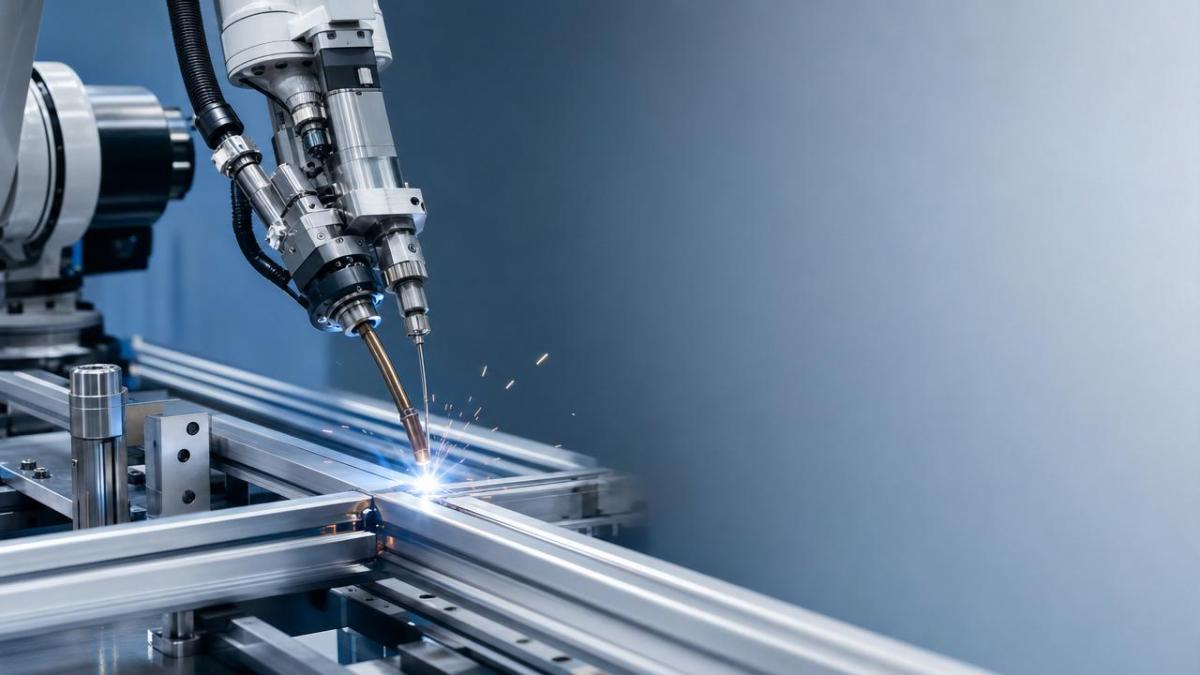
The first engineering reality is that robot welding aluminum profiles is not governed by robot repeatability alone. A robot may hold a path repeatability of ±0.02 mm to ±0.08 mm, but arc behavior depends on a wider system: material lot variation, profile geometry, contact tip condition, drive roll tension, gas flow stability, and thermal load. Spatter is often the visible result of several small deviations combining at the same time.
Surface oxide and contamination are common starting points
Aluminum naturally forms an oxide layer within minutes, and that layer has a melting temperature far above the base metal. When oil, coolant residue, dust, or fingerprints are added, arc ignition becomes less stable. In robot welding aluminum profiles, this often leads to local arc wandering, micro-explosions from trapped contamination, and erratic droplet transfer. The result is small but frequent spatter around the seam start, tack areas, or stop points.
For profiles stored for 7 to 30 days before welding, contamination risk usually increases unless packing, humidity, and handling are tightly managed. Even if visual inspection looks acceptable, a thin film of lubricant from extrusion or cutting operations can disturb wetting and arc stability. Operators should never assume that “clean-looking” aluminum is process-ready.
Typical contamination sources
- Extrusion lubricants left on profile surfaces
- Cutting fluid residue from sawing or machining
- Oxide build-up after extended storage
- Dust from nearby grinding or handling stations
- Moisture condensation when profiles move between temperature zones
Wire feed instability causes irregular transfer
The second major cause is wire feed behavior. Aluminum wire is softer than steel wire, so it is more sensitive to drive roll pressure, liner friction, wire cast, and contact tip wear. If feeding fluctuates even slightly, the arc length changes, current peaks become less predictable, and droplet transfer can turn violent. In many cells, spatter blamed on “bad parameters” is actually a feeding issue that developed gradually over 3 to 5 production days.
Push-pull torches, spool guns, and properly selected U-groove drive rolls can reduce this risk, but only if maintenance is consistent. A worn liner, oversized tip, or kinked conduit can produce intermittent resistance. Operators may then see short bursts of spatter at corners, seam starts, or when the robot accelerates through a direction change.
The table below outlines common process variables that frequently explain why robot welding aluminum profiles still produces spatter in routine production.
A key conclusion is that spatter is rarely caused by one variable in isolation. In most robot welding aluminum profiles applications, 3 to 4 factors interact. That is why short-term parameter adjustments may appear to help for one batch, but the problem returns when profile surface condition or wire path resistance changes again.
Arc tuning and transfer mode are often too narrow or too aggressive
Arc tuning matters more than many operators expect. On thin aluminum sections such as 1.5 mm to 3.0 mm wall profiles, a small increase in wire feed speed or voltage can shift the process window quickly. If the transfer becomes too harsh for the joint geometry, droplet detachment grows unstable and spatter increases. Pulse MIG and advanced waveform control can reduce this, but only when matched to alloy, wire diameter, and travel speed.
For example, switching from a stable pulse program to a higher deposition setting may improve throughput by 8% to 15%, yet also increase spatter if heat input is no longer balanced with the profile section. This is especially true in corners, heat-sinking nodes, or variable-mass assemblies where the weld pool responds differently every 100 to 300 mm.
The Five Process Areas Operators Should Check First
When robot welding aluminum profiles starts producing more spatter than normal, troubleshooting should follow a sequence rather than random parameter changes. A structured check can often isolate the main cause within 20 to 40 minutes. The five areas below cover most production cases.
1. Material preparation and storage control
Start with the part, not the robot. Confirm whether profiles were brushed, wiped, or otherwise cleaned before loading. Check storage age, packaging damage, and whether material moved through humid zones. In many factories, aluminum parts stored above 60% relative humidity or handled repeatedly without gloves show more oxidation and contamination. If spatter appears only on certain lots, this is a strong clue.
2. Wire feed path and torch consumables
Inspect drive rolls, liner, wire tension, contact tip size, and tip wear. Aluminum wire systems should be checked more frequently than steel systems, especially in high-volume cells. A practical interval is every 8 to 16 production hours for visual inspection and every 1 to 2 weeks for deeper maintenance, depending on duty cycle. If wire shaving is visible, resistance is already building in the feed path.
3. Gas flow, nozzle condition, and draft control
Shielding gas problems are often underestimated. In robot welding aluminum profiles, typical argon flow may sit around 15 to 25 L/min, but more flow is not always better. Excessive flow can create turbulence and pull air into the arc. Nozzle spatter build-up, damaged diffusers, or nearby ventilation drafts above roughly 0.3 to 0.5 m/s can break gas coverage and increase arc instability.
4. Joint fit-up and fixture consistency
Gap variation is one of the biggest hidden reasons why robot welding aluminum profiles still produces spatter. If the weld program assumes a 0.5 mm gap but actual fit-up ranges from 0.2 mm to 1.2 mm, the arc sees a moving target. The same waveform cannot remain optimal through the full joint. Profile straightness, clamp force, thermal distortion, and fixture wear all contribute.
5. Program settings and thermal behavior through the batch
Do not evaluate the process only on the first part. Aluminum heats quickly in production sequences. Part number 1 and part number 20 can behave differently if fixture temperature rises, tack sequence changes, or idle times vary. Watch for spatter growth later in the batch. That pattern usually indicates heat build-up, changing CTWD, or a program that is too sensitive to thermal variation.
The following checklist helps operators prioritize what to inspect before requesting a full parameter rewrite.
This table shows that practical troubleshooting is not abstract. Most spatter problems in robot welding aluminum profiles can be narrowed down through four to six checks tied directly to production variables. That is more effective than changing voltage, pulse balance, or travel speed without first confirming the mechanical and material basics.
How to Reduce Spatter Without Sacrificing Throughput
Reducing spatter does not always mean slowing the line. The goal is to widen the stable process window so the cell performs consistently across part variation, long shifts, and routine consumable wear. For most users and operators, this requires a combined approach rather than a single setting change.
Stabilize the input variables before retuning the arc
If surface cleaning, gas delivery, and wire feeding are unstable, arc tuning will not hold for long. Start by standardizing pre-weld preparation. A 3-step routine is often enough: verify lot condition, remove surface residue, and confirm fixture seating. Then inspect the feed path and gas system. Only after these are stable should the welding program be adjusted.
Use parameter trials with controlled increments
Avoid large jumps in voltage or wire feed speed. In aluminum profile work, even a change of 0.5 V to 1.0 V or a wire feed adjustment of 0.5 to 1.5 m/min can alter transfer significantly. Test one variable at a time over at least 5 to 10 consecutive parts. Record spatter pattern, bead profile, and cleaning time after welding. This turns troubleshooting into measurable process control rather than operator guesswork.
Good practice during trials
- Keep the same material lot during the test run.
- Measure fit-up at 3 or more positions along the joint.
- Check nozzle condition before each trial set.
- Compare first-part and warm-cell behavior after 30 to 60 minutes.
- Log spatter location, not only spatter quantity.
Improve fixture and path robustness
Where profile geometry varies, the fixture often determines whether robot welding aluminum profiles stays stable. Better clamping, reduced thermal lift, and consistent part seating can lower gap variation and improve torch access. Program refinements such as smoother approach angles, stable contact-tip-to-work distance, and better crater fill settings also help reduce end-spatter and restart defects.
Plan preventive maintenance around actual duty cycle
A cell running 16 hours per day needs a different maintenance rhythm than a cell running 4 hours. If spatter rises predictably after a certain production volume, build maintenance around that threshold. For example, some lines benefit from nozzle cleaning every 150 to 300 parts and tip checks every 1,000 to 2,000 arc starts. The exact interval depends on alloy, wire, pulse mode, and part complexity, but the principle is universal: wait too long, and arc stability drifts.
Common Misunderstandings in Aluminum Robotic Welding Cells
Operators often inherit assumptions that worked in steel welding but do not transfer well to aluminum. These misunderstandings can keep spatter levels high even when the equipment itself is capable of much better performance.
“If the robot path is accurate, the weld should be clean”
Path accuracy matters, but it cannot compensate for poor surface condition, bad gas shielding, or unstable feeding. A repeatable robot simply repeats the same conditions. If those conditions are flawed, spatter remains repeatable too.
“More gas flow always protects the weld better”
Higher gas flow can actually worsen spatter by creating turbulence. If the nozzle geometry, standoff, or surrounding airflow is wrong, pushing flow beyond the useful range may pull contamination into the arc instead of shielding it.
“Spatter is only a programming issue”
Programming affects torch angle, speed, and arc timing, but many spatter events begin with material and consumables. In robot welding aluminum profiles, good programming cannot fully overcome a dirty joint, a worn tip, or a gap that exceeds the intended process window.
What Buyers, Engineers, and Operators Should Ask Equipment Suppliers
For companies scaling robotic aluminum welding, supplier discussions should go beyond cycle time and robot brand. The more relevant questions concern process stability over time. Ask how the system handles wire feeding for soft aluminum alloys, what maintenance intervals are typical, how gas coverage is validated, and what joint variation the process can tolerate before quality drops.
It is also wise to request production-oriented validation criteria. Instead of generic claims, ask for acceptable fit-up range, recommended cleaning method, torch consumable schedule, and the number of consecutive parts used during process qualification. These details matter far more than broad promises when robot welding aluminum profiles must run reliably in real manufacturing conditions.
Spatter in robot welding aluminum profiles is usually a signal, not a mystery. It points to instability in one or more of five areas: surface condition, wire feed, arc tuning, gas behavior, or fit-up. When operators troubleshoot in that order and measure results over multiple parts, they can reduce rework, improve seam appearance, and protect production uptime without relying on guesswork.
At TechStat Vanguard, we focus on process truth that helps engineering teams make better decisions with fewer trial-and-error cycles. If you need deeper guidance on aluminum robotic welding cells, fixture strategy, consumable selection, or process benchmarking, contact us to get a tailored technical review, consult product details, or explore more hard-tech manufacturing solutions.
Search News
Hot Articles
- Carbon Fiber StructuresHow to Specify Aerospace Carbon Fiber Assemblies for Lightweight, Load-Bearing PartsJul 11, 2026
- Machine VisionXiaomi, Alibaba DAMO Academy Drive Open-Source Robotics Model Ecosystem, Lowering Algorithm Development Barriers for Overseas SMEs Adopting Chinese Robotics SolutionsMar 30, 2026
- Cobots & ArmsShanxi 'AI+' Conference Showcases Embodied Intelligence with Multinational Buyer Engagement: Key Industry ImplicationsMar 30, 2026
Popular Tags
Recommended News
 Jul 11, 2026How to Specify Aerospace Carbon Fiber Assemblies for Lightweight, Load-Bearing PartsAerospace carbon fiber assemblies: learn how to specify laminate design, load data, joining methods, and inspection controls for lighter, reliable load-bearing aerospace parts.Elena Rostova (UAV Systems Researcher)
 Mar 30, 2026Xiaomi, Alibaba DAMO Academy Drive Open-Source Robotics Model Ecosystem, Lowering Algorithm Development Barriers for Overseas SMEs Adopting Chinese Robotics SolutionsXiaomi & Alibaba DAMO Academy's open-source robotics models lower algorithm barriers for global SMEs. Boost efficiency in manufacturing, logistics & smart retail with ROS 2 compatible solutions.TSV Data Lab
 Mar 30, 2026Shanxi 'AI+' Conference Showcases Embodied Intelligence with Multinational Buyer Engagement: Key Industry ImplicationsShanxi 'AI+' Conference highlights embodied intelligence with Tesla, Ubtech & Jiantao showcasing multimodal robotics. 40+ global buyers validated tech on-site, creating new B2B channels for industrial automation & AI solutions.Chen Wei (Automation Lead Engineer)
 Mar 30, 2026Zhongguancun Unveils 6G Integrated Sensing-Computing-Intelligence Platform to Empower Embodied Robots for Global Industrial ApplicationsZhongguancun's new 6G platform revolutionizes industrial robotics with <10ms latency, empowering global automotive, logistics & port automation. Discover how this tech boosts China's smart manufacturing exports.TSV Data Lab
 Mar 30, 2026Mech-Mind Tianjin Embodied Intelligence R&D and Production Base Goes Live, Cutting Delivery Time by 20%–30% for Global Customized AMR+Vision SolutionsMech-Mind's Tianjin AMR+Vision production base cuts delivery time by 20%-30% for欧美 & Latin American markets. Discover how this PLd-certified facility accelerates customized robotics solutions for smart manufacturing and logistics.Chen Wei (Automation Lead Engineer)
 Mar 30, 2026Boao Forum Reveals 'Co-evolution of Big and Small Brains' Trend in Humanoid Robots, China's Embodied Intelligence Accelerates Adaptation to Overseas Manufacturing Service ScenariosDiscover how China's humanoid robots, featuring 'Co-evolution of Big and Small Brains,' are revolutionizing global manufacturing. Learn about Embodied Tian Gong 3.0's ISO compliance and overseas deployment at Boao Forum 2026.Chen Wei (Automation Lead Engineer)
 Mar 30, 2026China Railway Industrial Secures Patent for Embodied Robotics in Material Handling, Boosting High-Precision Delivery Capabilities for Overseas Infrastructure and Manufacturing ProjectsChina Railway Industrial's new patent for embodied robotics in material handling boosts high-precision delivery for global infrastructure & manufacturing. Discover how this innovation enhances logistics accuracy in automotive, rail transit & EPC projects.Chen Wei (Automation Lead Engineer)
 Sep 28, 2026Spindle Runout Measurement in Germany: DIN Standards, Methods, and Acceptance LimitsSpindle runout measurement Germany: explore DIN standards, proven methods, acceptance limits, and audit-ready practices for reliable machining quality.Dr. Marcus Vance
 Sep 27, 2026How to Select Wall-Mount Edge Devices for Space-Constrained Factory NetworksWall mount edge devices for space-constrained factories: evaluate workload, thermal design, power resilience, cable access, and network reliability for smarter deployments.TSV Data Lab
 Sep 26, 2026Machining Tolerance Analysis: How to Set Limits That Meet Function and Cost TargetsMachining tolerance analysis: learn how to set functional limits, control tolerance stacks, reduce inspection risk, and balance precision with production cost.Dr. Marcus Vance
 Sep 25, 2026How to Evaluate an Industrial Infrastructure Data Platform for Multi-Site OperationsIndustrial infrastructure data platform evaluation guide for multi-site operations: compare data quality, edge resilience, interoperability, governance, and scalable proof-of-value criteria.Victor Lin (Chief Software Architect)
 Sep 24, 2026How to Select Machine Vision Optics for Accurate Inspection at Different Working DistancesMachine vision optics selection guide for accurate inspection at every working distance. Compare FOV, pixel scale, DOF, distortion, lighting, and telecentric options.TSV Data Lab
 Sep 23, 2026How to Evaluate a Machine Vision System Integrator for High-Speed Inspection LinesChoose a machine vision system integrator with proven expertise in high-speed inspection, reliable reject timing, robust optics, and measurable acceptance criteria.TSV Data Lab
 Sep 28, 2026When is a SCADA API the right choice for connecting plant systems?SCADA API guide: learn when governed plant data integration improves traceability, security, and scalability—without compromising real-time control.Victor Lin (Chief Software Architect)
 Sep 27, 2026How SCADA data integration improves traceability across production linesSCADA data integration connects production-line data to improve traceability, accelerate quality investigations, and strengthen safety decisions.Victor Lin (Chief Software Architect)
 Sep 26, 2026What to define before starting SCADA integration planningSCADA integration planning starts with clear scope, control boundaries, data models, cybersecurity, and testing. Discover the definitions that reduce risk and costly rework.Victor Lin (Chief Software Architect)
 Sep 25, 2026How a smart factory with Industrial IoT reduces production blind spotsDiscover how a smart factory with Industrial IoT turns real-time machine, quality, and workflow data into actionable insights that reduce production blind spots and delivery risks.Victor Lin (Chief Software Architect)
 Sep 24, 2026When does Industrial IoT make smart manufacturing easier to scale?Smart manufacturing Industrial IoT scales when trusted data, interoperable systems, and secure workflows turn connected assets into measurable gains.TSV Data Lab
 Sep 23, 2026What drives ultra-precision machining cost at 1-micron tolerance?Ultra precision machining cost per part at 1 micron tolerance depends on process, material, metrology, and yield. Learn how to compare quotes confidently.Dr. Marcus Vance
 Sep 22, 2026Drone Engine-T550CC Applications: Build the UAV Power System Around the MissionAn application guide for Drone Engine-T550CC integration, covering payload planning, airframe matching, cooling, fuel, vibration, test procedures, documentation, and service preparation.Elena Rostova (UAV Systems Researcher)
 Sep 22, 2026How to Evaluate Industrial Edge Computing Vendors for Factory DeploymentIndustrial edge computing vendor evaluation guide for factories: compare latency, protocol fit, reliability, security, and lifecycle support before deployment.TSV Data Lab
 Sep 21, 2026Drone Payload Integration: Matching Power, Data, and Center of Gravity for Reliable FlightsDrone payload integration made practical: balance power, data, center of gravity, and endurance to build safer, more reliable mission-ready flights.Elena Rostova (UAV Systems Researcher)
 Sep 20, 2026Autonomous Navigation Pricing: Cost Drivers and Budget Benchmarks for AMR ProjectsAutonomous navigation price explained: compare AMR cost drivers, software, sensors, integration, safety, and lifecycle budgets to build a scalable project plan.Chen Wei (Automation Lead Engineer)
 Sep 19, 2026How to Scope Automation Integration Services for Multi-System Factory ProjectsAutomation integration services: learn how to scope multi-system factory projects with clear workflows, interface contracts, safety boundaries, and acceptance criteria.Victor Lin (Chief Software Architect)























