What cobot ISO/TS 15066 safety standard means on the floor
Publication Date
author
What does the cobot ISO/TS 15066 safety standard really mean on the factory floor? For engineering-led operations, it is not a badge. It is a practical framework for force, speed, contact, and risk control during human-robot collaboration.
In real production, the cobot ISO/TS 15066 safety standard helps translate abstract safety principles into measurable limits, validation steps, and system design choices. That matters across mixed-industry environments where uptime, repeatability, and operator protection must coexist.
What is the cobot ISO/TS 15066 safety standard, and why does it matter?
The cobot ISO/TS 15066 safety standard is a technical specification for collaborative robot applications. It builds on ISO 10218 and adds guidance for direct human-robot interaction.
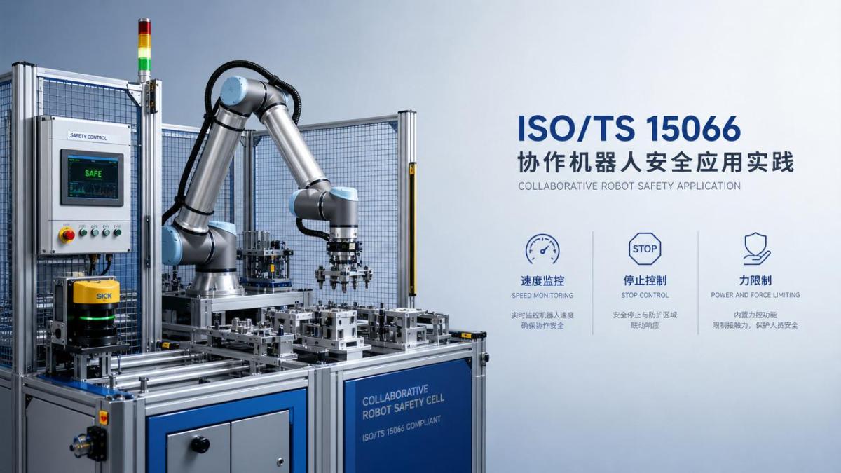
Its importance lies in floor-level interpretation. A robot may be collaborative in design, yet unsafe in deployment if tooling, payload, speed, or layout are poorly assessed.
The standard focuses on four collaboration methods:
- Safety-rated monitored stop
- Hand guiding
- Speed and separation monitoring
- Power and force limiting
These are not marketing labels. Each method demands specific sensors, control logic, validation procedures, and residual risk review.
For TechStat Vanguard’s engineering-first view, the key message is simple: collaborative safety is a system property, not a robot brochure feature.
How does the cobot ISO/TS 15066 safety standard affect real cell design?
On the floor, the cobot ISO/TS 15066 safety standard changes layout decisions early. Reach zones, part presentation, end-effector shape, and human approach paths must be considered together.
A common mistake is assuming the robot alone defines safety. In practice, the application often drives most of the risk.
Consider these design factors:
- Tool geometry and pinch points
- Payload inertia during acceleration
- Edge sharpness on fixtures and grippers
- Stopping distance at maximum process speed
- Operator posture during interaction
If separation monitoring is used, scanner placement and reaction time become critical. Blind spots or delayed braking can invalidate the intended protection concept.
If power and force limiting is used, contact thresholds must reflect body-region sensitivity. Shoulder contact differs from finger contact in acceptable transient force.
This is why engineering teams should validate the full operating envelope, not only nominal cycles. Abnormal part positions and maintenance modes matter too.
What does the standard actually say about force, pressure, and pain thresholds?
One reason the cobot ISO/TS 15066 safety standard is widely cited is its guidance on biomechanical limits. It provides reference values for acceptable transient and quasi-static contact.
That does not mean a universal safe number exists. Real values depend on contact area, body location, robot speed, and tool compliance.
In practical terms, floor teams should ask:
- Where can contact occur during normal operation?
- Is the contact transient or trapping?
- What tool or payload shape concentrates pressure?
- How fast can the robot move before reaching unsafe energy?
Pressure often becomes the hidden issue. A rounded gripper face may pass risk review, while a narrow bracket corner may fail despite lower overall force.
This is where data-driven validation matters. Force measurement devices, calibrated test methods, and documented stopping performance are more valuable than vendor claims.
For mixed-industry applications, especially electronics, packaging, light assembly, and lab automation, small tooling details often determine compliance feasibility.
Which applications benefit most, and where are the limits?
The cobot ISO/TS 15066 safety standard is most useful where shared workspace creates productivity value. Examples include kitting, screwdriving, machine tending, inspection, and packaging assistance.
It is less favorable when payloads are heavy, edges are hazardous, or cycle speed demands aggressive motion. In those cases, fencing or hybrid safeguarding may still be superior.
Applications often fit three broad categories:
The lesson is not that collaborative deployment is always better. It is that the chosen safety concept should match process physics, not commercial enthusiasm.
What are the biggest misconceptions about the cobot ISO/TS 15066 safety standard?
Misconception one: a cobot is automatically safe without guarding. False. The application must be risk assessed, then validated after installation.
Misconception two: low payload means low risk. Also false. Small tools can create high local pressure or entrapment hazards.
Misconception three: passing a demo proves compliance. Demonstrations rarely represent worst-case acceleration, maintenance access, or abnormal part conditions.
Misconception four: the standard removes the need for documentation. In reality, traceable records are central to defensible safety decisions.
A concise floor-level checklist helps avoid these traps:
- Review every operating mode, not only production mode
- Measure real stopping time and distance
- Assess tools, fixtures, and carried parts
- Validate after software or tooling changes
- Keep risk files current and auditable
How should implementation, cost, and validation be approached?
The cobot ISO/TS 15066 safety standard influences both timeline and total deployment cost. A low-entry robot can become expensive if validation is delayed until commissioning.
Early engineering work usually saves time later. That includes hazard review, sensor selection, tooling redesign, and stopping performance tests before production launch.
Implementation usually involves these stages:
- Define task boundaries and interaction points
- Select the collaborative operating mode
- Perform formal risk assessment
- Prototype tooling and measure contact behavior
- Validate safeguards under worst-case conditions
- Document changes and retrain affected personnel
For advanced manufacturing environments, verification discipline matters as much as robot selection. Parameters do not lie; assumptions do.
FAQ summary: what should be checked before approving a collaborative cell?
On the floor, the cobot ISO/TS 15066 safety standard means disciplined engineering. It turns collaborative robotics from a concept into a measurable safety architecture.
For any team comparing collaborative cells, the right next step is to map hazards, quantify contact conditions, and test the full system under realistic operating extremes.
That approach aligns with TechStat Vanguard’s core principle: engineering truth comes from verified parameters, not promotional language. In collaborative automation, that difference directly shapes safety, uptime, and long-term trust.
Search News
Hot Articles
- Carbon Fiber StructuresHow to Specify Aerospace Carbon Fiber Assemblies for Lightweight, Load-Bearing PartsJul 11, 2026
- Machine VisionXiaomi, Alibaba DAMO Academy Drive Open-Source Robotics Model Ecosystem, Lowering Algorithm Development Barriers for Overseas SMEs Adopting Chinese Robotics SolutionsMar 30, 2026
- Cobots & ArmsShanxi 'AI+' Conference Showcases Embodied Intelligence with Multinational Buyer Engagement: Key Industry ImplicationsMar 30, 2026
Popular Tags
Recommended News
 Jul 11, 2026How to Specify Aerospace Carbon Fiber Assemblies for Lightweight, Load-Bearing PartsAerospace carbon fiber assemblies: learn how to specify laminate design, load data, joining methods, and inspection controls for lighter, reliable load-bearing aerospace parts.Elena Rostova (UAV Systems Researcher)
 Mar 30, 2026Xiaomi, Alibaba DAMO Academy Drive Open-Source Robotics Model Ecosystem, Lowering Algorithm Development Barriers for Overseas SMEs Adopting Chinese Robotics SolutionsXiaomi & Alibaba DAMO Academy's open-source robotics models lower algorithm barriers for global SMEs. Boost efficiency in manufacturing, logistics & smart retail with ROS 2 compatible solutions.TSV Data Lab
 Mar 30, 2026Shanxi 'AI+' Conference Showcases Embodied Intelligence with Multinational Buyer Engagement: Key Industry ImplicationsShanxi 'AI+' Conference highlights embodied intelligence with Tesla, Ubtech & Jiantao showcasing multimodal robotics. 40+ global buyers validated tech on-site, creating new B2B channels for industrial automation & AI solutions.Chen Wei (Automation Lead Engineer)
 Mar 30, 2026Zhongguancun Unveils 6G Integrated Sensing-Computing-Intelligence Platform to Empower Embodied Robots for Global Industrial ApplicationsZhongguancun's new 6G platform revolutionizes industrial robotics with <10ms latency, empowering global automotive, logistics & port automation. Discover how this tech boosts China's smart manufacturing exports.TSV Data Lab
 Mar 30, 2026Mech-Mind Tianjin Embodied Intelligence R&D and Production Base Goes Live, Cutting Delivery Time by 20%–30% for Global Customized AMR+Vision SolutionsMech-Mind's Tianjin AMR+Vision production base cuts delivery time by 20%-30% for欧美 & Latin American markets. Discover how this PLd-certified facility accelerates customized robotics solutions for smart manufacturing and logistics.Chen Wei (Automation Lead Engineer)
 Mar 30, 2026Boao Forum Reveals 'Co-evolution of Big and Small Brains' Trend in Humanoid Robots, China's Embodied Intelligence Accelerates Adaptation to Overseas Manufacturing Service ScenariosDiscover how China's humanoid robots, featuring 'Co-evolution of Big and Small Brains,' are revolutionizing global manufacturing. Learn about Embodied Tian Gong 3.0's ISO compliance and overseas deployment at Boao Forum 2026.Chen Wei (Automation Lead Engineer)
 Mar 30, 2026China Railway Industrial Secures Patent for Embodied Robotics in Material Handling, Boosting High-Precision Delivery Capabilities for Overseas Infrastructure and Manufacturing ProjectsChina Railway Industrial's new patent for embodied robotics in material handling boosts high-precision delivery for global infrastructure & manufacturing. Discover how this innovation enhances logistics accuracy in automotive, rail transit & EPC projects.Chen Wei (Automation Lead Engineer)
 Oct 03, 2026Selecting Automotive Radar Sensor Modules for ADAS Range, Resolution, and IntegrationAutomotive radar sensor module selection guide for ADAS: compare range, resolution, field of view, latency, and integration to build safer, reliable vehicle systems.TSV Data Lab
 Oct 02, 2026How to Qualify Machined Parts Suppliers for Hard Tech ProgramsHard tech supply chain machined parts demand rigorous supplier qualification. Learn how to assess capability, traceability, quality controls, and delivery resilience.Dr. Marcus Vance
 Oct 01, 2026How to Select an Outdoor Security Radar Sensor for Perimeter Detection?Outdoor security radar sensor selection guide: compare range, accuracy, false-alarm control, integration, and field testing for reliable perimeter detection.TSV Data Lab
 Sep 30, 2026How to Evaluate Solid-State LiDAR Hardware for Outdoor Autonomous VehiclesSolid state LiDAR hardware evaluation guide for outdoor autonomous vehicles—compare range, point-cloud quality, environmental resilience, integration, and safety.TSV Data Lab
 Sep 29, 2026ISO 9283 Repeatability: How to Evaluate Cobot Positioning PerformanceISO 9283 cobot repeatability explained: learn how payload, reach, approach direction, and test conditions affect positioning performance and cell capability.Chen Wei (Automation Lead Engineer)
 Oct 03, 2026Is Edge Computing Necessary for Real-Time Quality Inspection?Is industrial edge computing necessary for real-time quality inspection? Explore how latency, data volume, reliability, and control integration shape the right architecture.TSV Data Lab
 Oct 02, 2026What Documents Prove a Precision Machining Supplier Can Hold Tolerance?What documents prove a precision machining supplier can hold tolerance? Explore certificates, FAI reports, calibration, SPC, and traceability evidence to qualify suppliers with confidence.Dr. Marcus Vance
 Oct 01, 2026Can a Machining Supplier Meet Aerospace Fatigue Testing Requirements?Can a machining supplier meet aerospace fatigue testing requirements? Learn the traceability, process control, and test evidence needed for reliable aerospace parts.Dr. Marcus Vance
 Sep 30, 2026Which Industrial Robot Specifications Matter for High-Precision Assembly?Which industrial robot specifications matter most for high-precision assembly? Explore repeatability, accuracy, stiffness, vibration, calibration, and force control for reliable yields.Chen Wei (Automation Lead Engineer)
 Sep 29, 2026How Do You Verify Servo Motor Torque Under Continuous Load?How do I verify servo motor torque under continuous load? Learn RMS torque checks, torque-speed limits, thermal derating, and real-machine testing.Chen Wei (Automation Lead Engineer)
 Oct 02, 2026ZD330 Software Configuration: Verifying Cut-List Import Before PurchaseZD330 software and machine configuration: verify cut-list imports, data mapping, labels, and workflow before purchase to reduce errors and choose with confidence.Victor Lin (Chief Software Architect)
 Sep 28, 2026Spindle Runout Measurement in Germany: DIN Standards, Methods, and Acceptance LimitsSpindle runout measurement Germany: explore DIN standards, proven methods, acceptance limits, and audit-ready practices for reliable machining quality.Dr. Marcus Vance
 Sep 27, 2026How to Select Wall-Mount Edge Devices for Space-Constrained Factory NetworksWall mount edge devices for space-constrained factories: evaluate workload, thermal design, power resilience, cable access, and network reliability for smarter deployments.TSV Data Lab
 Sep 26, 2026Machining Tolerance Analysis: How to Set Limits That Meet Function and Cost TargetsMachining tolerance analysis: learn how to set functional limits, control tolerance stacks, reduce inspection risk, and balance precision with production cost.Dr. Marcus Vance
 Sep 25, 2026How to Evaluate an Industrial Infrastructure Data Platform for Multi-Site OperationsIndustrial infrastructure data platform evaluation guide for multi-site operations: compare data quality, edge resilience, interoperability, governance, and scalable proof-of-value criteria.Victor Lin (Chief Software Architect)
 Sep 24, 2026How to Select Machine Vision Optics for Accurate Inspection at Different Working DistancesMachine vision optics selection guide for accurate inspection at every working distance. Compare FOV, pixel scale, DOF, distortion, lighting, and telecentric options.TSV Data Lab
 Sep 23, 2026How to Evaluate a Machine Vision System Integrator for High-Speed Inspection LinesChoose a machine vision system integrator with proven expertise in high-speed inspection, reliable reject timing, robust optics, and measurable acceptance criteria.TSV Data Lab