Robotic arm for electronics assembly: what specs matter
Publication Date
author
Choosing the right robotic arm for electronics assembly is not about brand claims—it is about measurable engineering fit. For R&D teams, operators, buyers, and executives, the critical question is which specs truly affect precision, cycle time, ESD safety, payload stability, and integration cost. This guide breaks down the parameters that matter most when evaluating a robotic arm for electronics assembly in real production environments.
In electronics manufacturing, a robotic arm is rarely judged by payload alone. Surface-mount support, screwdriving, dispensing, inspection handoff, micro-part pick-and-place, and test fixture loading all impose different requirements. A 3 kg arm with better repeatability, lower vibration, and cleaner cable routing can outperform a 10 kg arm in a PCB or semiconductor-adjacent cell.
This matters because electronics assembly margins are shaped by defects per million, line balancing, changeover speed, and downtime recovery. For procurement teams, the wrong specification set often leads to overbuying capital equipment in one area while underestimating integration, end-effector, and control costs in another.
From the TechStat Vanguard perspective, the most useful approach is to filter marketing language and compare engineering parameters that affect real throughput and yield. The sections below focus on the specs that most often change buying decisions, factory acceptance criteria, and long-term total cost of ownership.
Precision, repeatability, and motion stability for small-part assembly
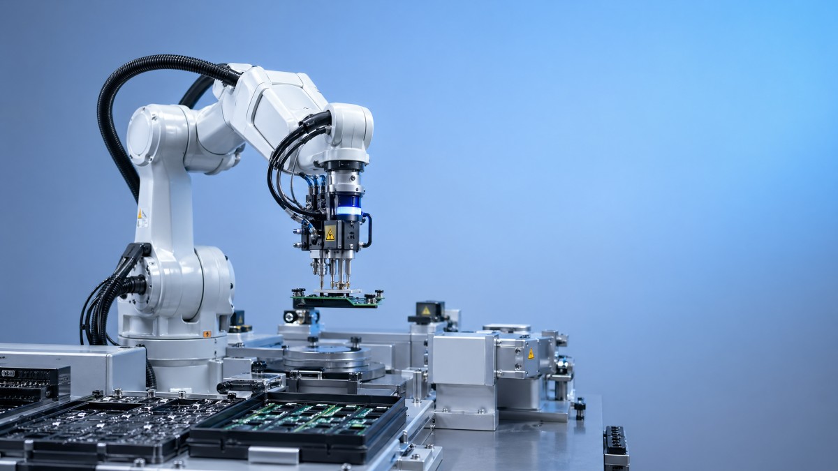
For electronics assembly, repeatability is usually the first parameter buyers check, but it should not be read in isolation. A robotic arm advertised at ±0.02 mm repeatability may still underperform in a live cell if joint backlash, tool offset drift, base vibration, or acceleration tuning are poorly controlled. In fine assembly, the usable process window is often narrower than the published robot specification.
As a practical rule, operations involving connector insertion, camera-guided part placement, or micro-screw positioning often benefit from repeatability in the ±0.01 mm to ±0.03 mm range. For tray loading or less sensitive material transfer, ±0.05 mm may be acceptable. However, if the end effector includes compliance, force control, or vision correction, system-level accuracy can differ significantly from robot-only numbers.
Why stability matters as much as nominal accuracy
Electronics assembly tasks are sensitive to micro-vibration. A robot can hit a target point repeatedly in a test cycle and still create process instability if it oscillates at stop points or settles too slowly. In high-mix lines with cycle times of 3 to 8 seconds, even an extra 0.2 to 0.4 seconds of settling time per move can reduce hourly output by a meaningful margin.
This is why engineers should review acceleration, jerk control, arm rigidity, and mounting conditions. A tabletop installation on a lightly reinforced frame behaves differently from a floor-mounted pedestal. The same arm may deliver different insertion performance depending on whether it handles a 50 g suction tool or a 1.5 kg servo screwdriver with cable drag.
Key questions for acceptance testing
- What is the robot’s repeatability at the rated speed rather than at a reduced demo speed?
- How much settling time is required after a 300 mm or 500 mm move before the tool can perform insertion or dispensing?
- Does the supplier validate performance with the actual end effector mass, cable pack, and mounting structure?
- How does the arm behave after 8 to 12 hours of thermal drift in continuous production?
The table below summarizes how common precision metrics should be interpreted for electronics assembly rather than general-purpose handling.
The main takeaway is that a robotic arm for electronics assembly should be selected on system behavior, not on brochure accuracy alone. Repeatability, settling time, and drift should be validated together under production-like duty cycles.
Payload, reach, and end-effector matching without oversizing
Payload selection is one of the most common sources of mismatch. Many buyers add a large safety buffer and end up purchasing an arm that is heavier, slower to tune, and more expensive to integrate than necessary. In electronics assembly, actual handled parts may weigh only 5 g to 500 g, but the total moving mass also includes the gripper, vision bracket, compliance module, air fittings, cable routing, and sometimes a screw feeder nosepiece.
A sound engineering method is to calculate total tool-side moving mass and then apply a practical reserve of around 20% to 30%, not an arbitrary 100% oversize factor. For example, if the combined end effector and part mass is 1.8 kg, an arm rated at 3 kg may be enough if the motion profile is moderate. If the process involves high acceleration, long reach, or off-axis moments, a 4 kg to 5 kg class may be safer.
Reach should be based on the actual work envelope
Reach affects more than coverage. Longer arms often create larger deflection at the tool center point, especially near the edge of the workspace. In electronics cells, common reach bands such as 500 mm to 900 mm usually fit benchtop tasks, feeder access, tray loading, and fixture transfer. Moving to 1,200 mm or beyond may solve layout problems but can also raise cycle time and reduce stiffness.
Engineers should map the real positions of feeders, conveyors, test nests, reject bins, and operator access zones before choosing arm length. A compact 6-axis arm placed closer to the work zone often performs better than a longer arm forced to stretch across a crowded cell.
When oversizing creates hidden cost
- Higher robot mass can require a stronger base frame and better vibration isolation.
- Larger arms may need more safety spacing, limiting dense line layouts.
- Bigger motors can increase power draw and raise cabinet size or thermal load.
- Programming and speed optimization often take longer when inertia is high and paths are tight.
The following comparison helps teams align payload and reach with common electronics assembly tasks.
For most projects, the right robotic arm for electronics assembly is the smallest model that still meets payload, wrist torque, and reach requirements with a realistic reserve. That choice usually improves responsiveness, lowers integration complexity, and protects floor space.
ESD, cleanliness, and control-system compatibility
Electronics manufacturing places special demands on electrostatic discharge control and contamination management. A robotic arm that performs well in automotive handling may still be unsuitable near exposed boards, sensors, flex circuits, or semiconductor-adjacent subassemblies. Buyers should ask whether the arm, dress pack, gripper materials, and grounding path are compatible with the plant’s ESD control strategy.
In many facilities, the robotic system must work inside an EPA, or electrostatic protected area. That means not only using dissipative materials where needed, but also verifying grounding continuity, cable shielding, and interface behavior with peripheral devices. If the robot communicates with smart feeders, vision controllers, torque tools, and MES gateways, signal integrity and grounding design become part of yield protection, not just electrical compliance.
Clean routing and I/O design reduce downtime
Electronics lines often have dense peripherals: barcode readers, screw presenters, ionizers, cameras, trays, and test fixtures. Poor cable routing can create particle generation, maintenance delays, and repeat faults. Internal routing or well-managed external dress packs are often preferable when the cell performs thousands of cycles per shift and operators need unobstructed access.
Control compatibility also affects commissioning time. Ethernet/IP, PROFINET, EtherCAT, Modbus TCP, and digital I/O may all appear in electronics factories. If the robotic arm requires custom middleware for basic handshakes with vision or torque tools, integration time can expand from 2 weeks to 6 weeks or more, especially in a validated production environment.
Checklist for ESD and controls review
- Confirm whether the robot and end effector can be incorporated into the site ESD grounding scheme.
- Review cable shielding, connector robustness, and moving cable life under full duty cycles.
- Check supported industrial protocols and native interfaces for cameras, PLCs, torque tools, and MES layers.
- Verify controller footprint, heat output, and cabinet placement in space-constrained cells.
- Assess whether remote diagnostics and event logging are available for fault tracing.
The table below highlights the control and environment factors that frequently affect electronics projects after purchase.
For procurement and engineering teams, these “secondary” specifications often decide whether a robotic arm becomes a stable production asset or a source of recurring line-support work. In electronics assembly, ESD and controls compatibility should be specified before RFQ, not after installation.
Cycle time, software usability, and integration cost
A robotic arm for electronics assembly should not be evaluated by hardware metrics alone. Software usability, teaching method, vision integration, recipe changeover, and maintenance workflow all shape the true cost of ownership. A robot that is slightly cheaper upfront can become more expensive if every product change requires specialist programming or line stoppage.
In many electronics factories, product life cycles are short and SKU variation is high. That means changeovers may happen weekly, daily, or even several times per shift. If recipe switching, coordinate updates, and tool calibration take 20 to 30 minutes per change, annual lost production time can be substantial. A system designed for 5 to 10 minute guided changeovers often creates better payback than a faster arm with complex setup routines.
What drives integration cost most often
Integration cost usually comes from five areas: tooling design, safety design, software interfacing, vision calibration, and production validation. In electronics assembly, end effectors are rarely generic. Vacuum tooling may need anti-static materials, screwdriving heads may need torque traceability, and compliance modules may need force tuning for connector insertion. These subsystems can equal or exceed the robot cost in compact, high-precision cells.
Decision-makers should therefore compare the full cell budget, not only the robotic arm price. A practical review includes spare-part policy, operator training hours, service response time, and the availability of local integration support. Even a 48-hour delay in support can be significant on a line running 2 or 3 shifts per day.
A practical 4-step selection process
- Define the process window: target takt time, required precision, part variability, ESD requirements, and shift pattern.
- Build the real load model: part mass, tool mass, wrist moment, cable drag, and reach envelope.
- Request proof by application: ask suppliers to simulate or test the actual task, not a generic pick-and-place demo.
- Evaluate lifecycle factors: training, spare parts, remote diagnostics, and upgrade path for future SKUs.
The strongest purchase decisions usually come from cross-functional review. R&D checks process capability, operators assess usability, procurement compares lifecycle cost, and executives review scale-up potential across multiple lines or sites.
If your team is drafting a specification sheet, focus first on measurable criteria: repeatability target, payload with tooling, reach envelope, supported protocols, changeover time, alarm logging, and acceptance-test conditions. That approach aligns with TSV’s engineering-first philosophy: parameters do not lie, and tolerance-driven decisions reduce both sourcing risk and trial-and-error cost.
Common buying mistakes and final evaluation criteria
Several mistakes repeat across electronics automation projects. The first is overvaluing top speed without measuring process dwell, alignment time, and downstream bottlenecks. The second is treating published payload as the only load metric while ignoring wrist moment and center-of-gravity offset. The third is postponing ESD and software interface reviews until after the machine order is placed.
Another common error is accepting a vendor demo that does not reflect the real production environment. A clean showroom motion test may not reveal how the robotic arm behaves with live feeders, awkward cable routing, reflective parts, or operator traffic. In electronics assembly, the meaningful benchmark is performance over repeated cycles, often measured over 1,000 to 10,000 repetitions depending on process sensitivity.
Final criteria before purchase approval
- Can the system achieve the required takt time with the actual tool and part, not with an empty wrist?
- Has repeatability been verified at the target workspace position, especially near reach limits?
- Are protocol compatibility, alarm diagnostics, and recipe management clear enough for plant maintenance teams?
- Does the supplier define FAT and SAT acceptance criteria in measurable terms such as cycle time, pass rate, and calibration drift?
- Is the spare-parts and service model realistic for 24/7 or near-continuous production?
Short FAQ for research and procurement teams
How much repeatability is enough for electronics assembly? It depends on the task. Fine insertion and micro-positioning often require ±0.01 mm to ±0.03 mm. Basic transfer tasks may function well at ±0.05 mm, provided motion settling and vision correction are adequate.
Is a collaborative robot always the best choice? Not necessarily. Cobots can simplify deployment and operator interaction, but for very high-speed or very rigid precision tasks, a traditional industrial arm may offer better throughput or stiffness.
What is a realistic integration timeline? A straightforward cell may be deployed in 2 to 6 weeks, while systems involving vision, traceability, screwdriving, and validation can take 6 to 12 weeks or longer depending on plant readiness and software scope.
What should procurement request in an RFQ? Ask for repeatability, payload with wrist moment limits, reach, supported protocols, controller footprint, recommended maintenance interval, spare-part list, and test conditions used to validate cycle time and precision.
A well-chosen robotic arm for electronics assembly is one that fits the process window with measurable discipline. Precision, payload reserve, reach, ESD compatibility, controls integration, and changeover usability should be assessed as one system. If your team is comparing options or drafting technical requirements, contact us to get a data-driven evaluation framework, a tailored spec checklist, or deeper guidance on robotics and automation solutions for electronics production.
Search News
Hot Articles
- Carbon Fiber StructuresHow to Specify Aerospace Carbon Fiber Assemblies for Lightweight, Load-Bearing PartsJul 11, 2026
- Machine VisionXiaomi, Alibaba DAMO Academy Drive Open-Source Robotics Model Ecosystem, Lowering Algorithm Development Barriers for Overseas SMEs Adopting Chinese Robotics SolutionsMar 30, 2026
- Cobots & ArmsShanxi 'AI+' Conference Showcases Embodied Intelligence with Multinational Buyer Engagement: Key Industry ImplicationsMar 30, 2026
Popular Tags
Recommended News
 Jul 11, 2026How to Specify Aerospace Carbon Fiber Assemblies for Lightweight, Load-Bearing PartsAerospace carbon fiber assemblies: learn how to specify laminate design, load data, joining methods, and inspection controls for lighter, reliable load-bearing aerospace parts.Elena Rostova (UAV Systems Researcher)
 Mar 30, 2026Xiaomi, Alibaba DAMO Academy Drive Open-Source Robotics Model Ecosystem, Lowering Algorithm Development Barriers for Overseas SMEs Adopting Chinese Robotics SolutionsXiaomi & Alibaba DAMO Academy's open-source robotics models lower algorithm barriers for global SMEs. Boost efficiency in manufacturing, logistics & smart retail with ROS 2 compatible solutions.TSV Data Lab
 Mar 30, 2026Shanxi 'AI+' Conference Showcases Embodied Intelligence with Multinational Buyer Engagement: Key Industry ImplicationsShanxi 'AI+' Conference highlights embodied intelligence with Tesla, Ubtech & Jiantao showcasing multimodal robotics. 40+ global buyers validated tech on-site, creating new B2B channels for industrial automation & AI solutions.Chen Wei (Automation Lead Engineer)
 Mar 30, 2026Zhongguancun Unveils 6G Integrated Sensing-Computing-Intelligence Platform to Empower Embodied Robots for Global Industrial ApplicationsZhongguancun's new 6G platform revolutionizes industrial robotics with <10ms latency, empowering global automotive, logistics & port automation. Discover how this tech boosts China's smart manufacturing exports.TSV Data Lab
 Mar 30, 2026Mech-Mind Tianjin Embodied Intelligence R&D and Production Base Goes Live, Cutting Delivery Time by 20%–30% for Global Customized AMR+Vision SolutionsMech-Mind's Tianjin AMR+Vision production base cuts delivery time by 20%-30% for欧美 & Latin American markets. Discover how this PLd-certified facility accelerates customized robotics solutions for smart manufacturing and logistics.Chen Wei (Automation Lead Engineer)
 Mar 30, 2026Boao Forum Reveals 'Co-evolution of Big and Small Brains' Trend in Humanoid Robots, China's Embodied Intelligence Accelerates Adaptation to Overseas Manufacturing Service ScenariosDiscover how China's humanoid robots, featuring 'Co-evolution of Big and Small Brains,' are revolutionizing global manufacturing. Learn about Embodied Tian Gong 3.0's ISO compliance and overseas deployment at Boao Forum 2026.Chen Wei (Automation Lead Engineer)
 Mar 30, 2026China Railway Industrial Secures Patent for Embodied Robotics in Material Handling, Boosting High-Precision Delivery Capabilities for Overseas Infrastructure and Manufacturing ProjectsChina Railway Industrial's new patent for embodied robotics in material handling boosts high-precision delivery for global infrastructure & manufacturing. Discover how this innovation enhances logistics accuracy in automotive, rail transit & EPC projects.Chen Wei (Automation Lead Engineer)
 Oct 26, 2026AMAXiMAL Releases Open-Source TopMod 3D v3 With Claude AIExplore AMAXiMAL’s free, open-source TopMod 3D v3 with Claude AI assistance, topology-based modeling and plywood fabrication tools that connect complex designs to physical builds.Dr. Marcus Vance
 Oct 26, 2026Choosing a SCADA System Integrator Company: PLC Compatibility and Long-Term SupportChoose a scada system integrator company with proven PLC compatibility and reliable long-term support. Discover what to test, compare, and require before investing.Victor Lin (Chief Software Architect)
 Oct 25, 2026Hesai Leads Global ADAS Main Lidar Shipments in Yole’s 2026 ReportHesai led global ADAS main lidar shipments with a 43% share in 2025, according to Yole’s 2026 report. Explore what this ranking reveals about its automotive market position.TSV Data Lab
 Oct 25, 2026Choosing an Aerospace Materials Manufacturer: Quality and Traceability ChecksChoosing an aerospace materials manufacturer? Learn how to verify certifications, test reports, and lot traceability to qualify suppliers confidently and reduce costly sourcing risks.Dr. Marcus Vance
 Oct 24, 2026Guotai Haitong: Global Entry-Level 3D Printer Shipments Rose 39% in Q1 2026Entry-level 3D printer shipments rose 39% in Q1 2026, Guotai Haitong reports. Explore how AI, multicolor printing and print farms are shaping market growth.Dr. Marcus Vance
 Oct 24, 2026Choosing an Industrial Vision Inspection Supplier: Acceptance Tests That MatterChoose an industrial vision inspection supplier with confidence. Discover acceptance tests for defect detection, false rejects, production speed, and reliable part rejection before you buy.TSV Data Lab
 Oct 23, 2026US Navy Raises Gecko Robotics Contract Ceiling to $300M for Robotic Fleet MaintenanceUS Navy raises Gecko Robotics’ contract ceiling to $300M for Pacific Fleet robotic inspections. Explore potential opportunities for maintenance suppliers and key procurement considerations.Chen Wei (Automation Lead Engineer)
 Oct 23, 2026Choosing Industrial Sensing Systems for Global Plants: Protocol CompatibilityCompare industrial sensing systems international buyers can trust. Explore protocol compatibility, reduce integration risks, and select proven configurations for reliable global plant deployments.TSV Data Lab
 Oct 22, 2026KUKA Showcases Physical AI and iiQKA.AI Vision at NVIDIA GTC BerlinExplore KUKA’s Physical AI showcase at NVIDIA GTC Berlin and discover how iiQKA.AI Vision aims to simplify robotic vision integration and improve 2D and 3D scene recognition.TSV Data Lab
 Oct 22, 2026Robotic Machining of Advanced Composites: What Tolerances Are Achievable?Explore advanced materials machining robotics: discover what drives achievable composite tolerances and how to validate accuracy before investing in your next machining system.Dr. Marcus Vance
 Oct 21, 2026China’s Industrial Robot Exports Near RMB 10 Billion in First Nine Months of 2026China’s industrial robot exports neared RMB 10 billion in January–September 2026, with value rising faster than volume. Explore the data and what it could mean for suppliers.Chen Wei (Automation Lead Engineer)
 Oct 21, 2026Low-Latency Industrial Data Processing: Pricing and Key Cost DriversExplore industrial data latency price drivers, from edge hardware to integration and support. Learn how to compare quotes, verify performance, and avoid unnecessary costs.TSV Data Lab
 Oct 20, 2026KUKA Launches iiQKA.AI Vision to Simplify Industrial Image ProcessingKUKA iiQKA.AI Vision simplifies industrial image processing with controller-based 2D and 3D vision. Explore drag-and-drop setup for vision-guided automation.TSV Data Lab
 Oct 20, 2026Smart Industrial Edge Devices: Key Criteria for Legacy PLC IntegrationChoose smart industrial edge devices for legacy PLC integration. Discover key criteria for compatibility, data quality, security, and reliable collection without disrupting control.TSV Data Lab
 Oct 19, 2026Choosing a Radar Sensor by Application: Range, Resolution, and Field of ViewSimplify radar sensor application based product selection. Compare range, resolution, and field of view to avoid blind spots and choose with confidence. Explore the guide.TSV Data Lab
 Oct 18, 2026Comparing Material Options for Procurement: Specs, Costs, and Supply RisksExplore procurement oriented technical content on material options, specs, costs, and supply risks. Compare alternatives to cut hidden expenses and make confident sourcing decisions.Dr. Marcus Vance
 Oct 17, 20265-Axis CNC Positioning Accuracy: How to Interpret ISO 230-2 Test ResultsAssess 5 axis CNC machining positioning accuracy with ISO 230-2. Learn to interpret repeatability, reversal error, and test conditions to compare suppliers and make confident acceptance decisions.Dr. Marcus Vance