Robot Welding Aluminum Profiles: What Causes Weak or Uneven Seams?
Publication Date
author
In robot welding aluminum profiles, weak or uneven seams rarely stem from a single defect. They usually reflect a chain of issues—from heat input instability and joint fit-up variation to servo motor torque curve analysis, robotic arm vibration analysis, and inconsistent shielding control. For engineers, operators, buyers, and plant leaders evaluating smart factory automation solutions, understanding these root causes is essential to improving weld quality, repeatability, and long-term production confidence.
Aluminum profile welding is less forgiving than many steel applications. Its high thermal conductivity, oxide layer behavior, and sensitivity to contamination mean that even a deviation of 0.2–0.5 mm in joint gap, a slight fluctuation in wire feed, or a short shielding gas disturbance can change bead shape and penetration. In automated lines, these variations are often amplified by robot path programming, fixture wear, torch angle drift, and inconsistent upstream cutting quality.
For B2B decision-makers, the question is not only how to repair a weak seam after it appears, but how to identify the real source before defects affect throughput, rework cost, or qualification risk. A robot cell that looks stable in trial production may still fail under 2-shift or 3-shift operation if the process window is too narrow. This is why a data-driven view matters more than broad claims about automation performance.
This article breaks down the most common causes of weak or uneven seams in robotic aluminum profile welding, the parameters worth monitoring, and the practical selection points for engineering teams, operators, procurement specialists, and plant leadership. The goal is simple: reduce trial-and-error, improve weld consistency, and support better investment decisions in robotic welding systems.
Why Aluminum Profiles Expose Process Instability Faster Than Other Materials
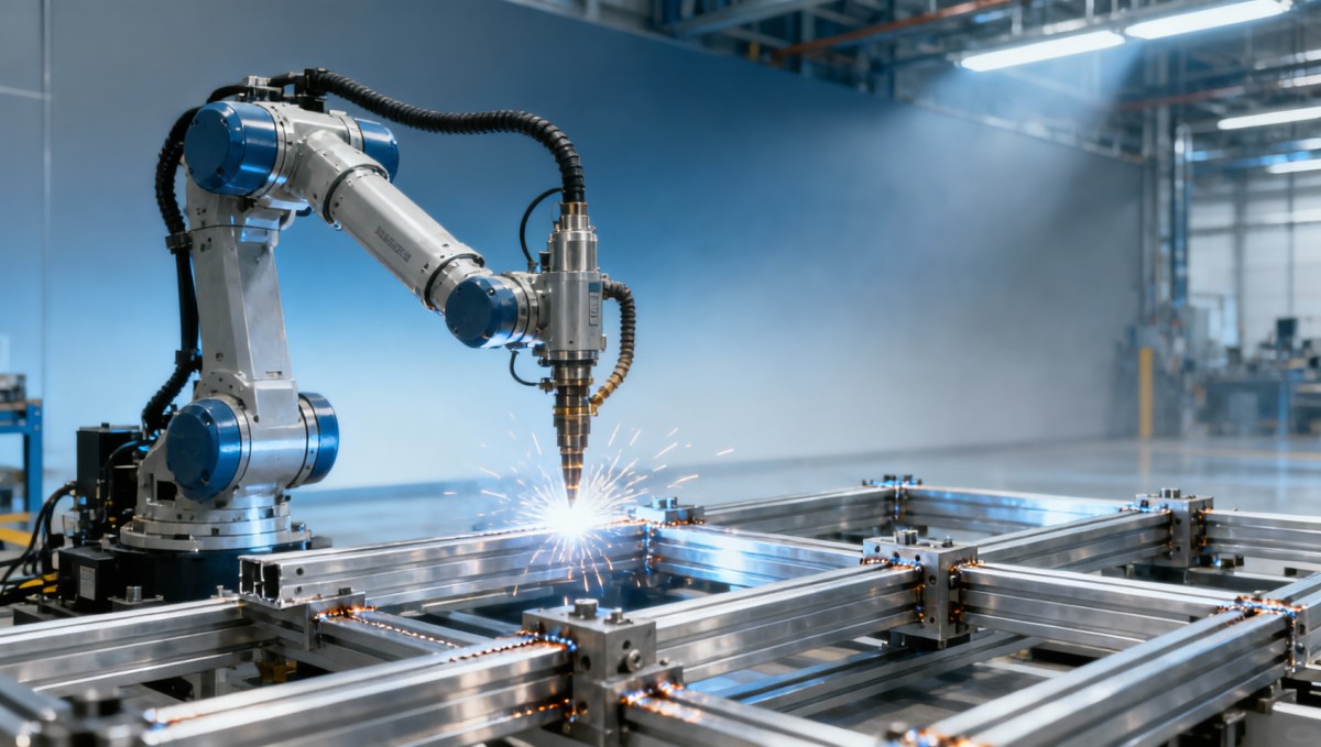
Aluminum profiles behave differently from carbon steel because they transfer heat quickly, soften rapidly in localized zones, and develop an oxide layer with a melting point far above the base metal itself. In practice, this means the weld pool can change shape within milliseconds if arc length, travel speed, or current output drifts outside a controlled range. In robotic production, even small instability becomes visible as underfill, lack of fusion, porosity, or inconsistent bead width.
Profile geometry adds another challenge. Many industrial aluminum profiles include thin walls, hollow chambers, corners, ribs, or variable section thicknesses. A 2.0 mm wall and a 4.0 mm reinforcement section on the same part do not absorb heat equally. If the welding program uses one fixed parameter set across the entire joint, the result is often uneven seam formation. This is especially common in frames, enclosures, battery structures, rail components, and lightweight automation assemblies.
Another issue is fit-up variation from upstream processes. Saw cutting, extrusion straightness, machining burrs, and fixture clamping all influence how consistently parts present themselves to the robot. When the joint gap changes from 0.3 mm to 1.0 mm along a seam, the arc sees a different load condition, and a parameter set that worked for one segment may fail in the next. Many weak seam problems are therefore manufacturing system problems, not only welding head problems.
From a purchasing and plant management standpoint, aluminum robotic welding should be evaluated as a complete process chain. Repeatability claims such as ±0.02 mm robot arm repeatability sound impressive, but they do not guarantee seam consistency if the torch mount flexes, the fixture shifts by 0.4 mm, or the profile itself varies beyond tolerance. The practical process window is defined by the weakest link in the cell.
Typical material and process sensitivities
The table below summarizes why robotic aluminum profile welding tends to reveal hidden process instability earlier than many other automated joining applications.
The key takeaway is that a weak or uneven seam in aluminum profile welding is often the first visible symptom of a wider control problem. Teams that monitor only the final bead appearance may miss the upstream deviations that created the defect in the first place.
The Most Common Root Causes of Weak or Uneven Robot Weld Seams
In most production cells, seam inconsistency comes from four interacting categories: heat input instability, joint presentation error, mechanical motion issues, and shielding or consumable inconsistency. Rarely does one variable act alone. For example, a slightly worn fixture may increase gap variation, which forces the arc to bridge more space, which then exposes insufficient wire feed tuning and leads to underfilled areas.
Heat input instability is often tied to travel speed, arc length, pulse setting, or power source response. If the robot slows down at corners without compensating current and wire feed, local heat input rises. If it accelerates on straight sections too aggressively, penetration may drop. In aluminum MIG or pulse MIG applications, even a 5-10% mismatch between programmed speed and actual heat requirement can change seam profile significantly on thin sections.
Joint fit-up variation remains one of the most underestimated causes. Profiles may look dimensionally acceptable at incoming inspection, yet still present inconsistent edge conditions during clamping. A fixture that applies uneven force can twist parts slightly, changing torch-to-joint distance and angle. When robotic welding is expected to compensate for poor part preparation, the seam often becomes visually uneven and mechanically weaker.
Mechanical motion quality also matters. Servo motor torque curve analysis can reveal whether axis loading is smooth throughout the weld path or whether there are spikes during acceleration, reorientation, or overhead positions. Robotic arm vibration analysis is equally important, particularly on long-reach arms, floor-mounted cells, or gantry-linked systems. Vibration amplitudes that seem minor can still disturb arc stability enough to create waviness, inconsistent toe shape, or intermittent fusion loss.
Shielding gas issues are another frequent source of weak seams. Aluminum welds are highly sensitive to gas flow disruption, nozzle contamination, and draft exposure. A nominal flow of 15-20 L/min may still be ineffective if nozzle distance increases, the gas cup is partially blocked by spatter, or local air movement exceeds what the shielding envelope can tolerate. The defect then appears as porosity or dull, rough seam texture rather than a dramatic process alarm.
Root-cause checklist for troubleshooting
- Verify whether joint gap remains within a stable band, ideally controlled to a repeatable process window rather than allowed to float across the seam.
- Check actual torch angle and stick-out during robot motion, not only in the teaching position.
- Review servo load data for axis spikes, especially where the path includes sharp turns, elevation changes, or abrupt speed shifts.
- Inspect gas nozzles, liners, contact tips, and wire condition at routine intervals such as every 1 shift or every 8-12 production hours.
- Compare defect location against fixture contact points to determine whether clamping distortion is influencing seam geometry.
Typical symptom-to-cause mapping
A practical troubleshooting model is to map each visible seam defect to a likely process source. This shortens diagnosis time and reduces unnecessary parameter changes.
This mapping helps teams avoid a common mistake: changing filler wire, shielding gas, and current all at once. Controlled diagnosis is faster and more reliable when one variable family is verified at a time.
What Data Engineers and Operators Should Monitor in Real Production
A stable robotic aluminum welding cell is built on measurable process signals, not only visual inspection. Engineers should monitor actual travel speed, current, voltage, wire feed stability, torch TCP deviation, servo load trend, and gas delivery consistency. Operators should be able to recognize whether defects repeat at the same position, after a certain number of parts, or during certain thermal conditions such as the first 30 minutes of start-up versus mid-shift steady production.
Servo motor torque curve analysis is especially useful because it reveals hidden resistance, drag, imbalance, or fixture interference. If one axis repeatedly shows torque peaks 15-25% above its stable baseline during the same weld segment, the problem may not be electrical at all. It could indicate cable pack tension, mounting looseness, or an overly aggressive path. Over time, these dynamic disturbances reduce seam consistency even when the weld parameters remain unchanged.
Robotic arm vibration analysis should not be limited to obvious chatter. Subtle oscillation at tool center point can affect arc length on thin-wall aluminum profiles. In many plants, vibration rises when reach exceeds 70-80% of robot working envelope, when the positioner changes acceleration profile, or when the floor foundation transmits resonance from nearby equipment. Monitoring these conditions can explain why one workstation consistently outperforms another using the same robot model and power source.
Shielding control deserves equal attention. Gas flow setpoint is only one variable. Actual delivery depends on hose integrity, regulator stability, nozzle cleanliness, and ambient air movement. In open workshop environments, cross-drafts from HVAC systems, doors, or extraction placement can disrupt the gas envelope. A flow meter reading of 18 L/min is not a guarantee of weld protection if the shielding zone collapses at the arc.
Core monitoring points for a robotic aluminum welding cell
- Track seam defects by position and batch, so recurring issues are linked to a process stage rather than treated as isolated events.
- Record wire consumable changes, tip replacement intervals, and nozzle cleaning frequency to identify maintenance-related drift.
- Trend servo loads and axis temperatures over at least 2-4 weeks to detect motion degradation before visible seam quality loss.
- Audit fixture accuracy on a routine schedule, such as every 500-1,000 cycles for high-volume lines.
- Correlate weld quality with environmental variables including shift timing, air flow, and material cleaning interval.
For procurement teams comparing automation suppliers, this is a key distinction: strong vendors can show which process data they expose to the plant, how often it can be logged, and how maintenance thresholds are defined. A robotic welding cell without transparent diagnostics may appear lower in upfront cost but create higher hidden cost through rework and unstable throughput.
How to Improve Seam Strength and Uniformity in Automated Aluminum Welding
Improving weak or uneven seams requires coordinated control of preparation, programming, mechanics, and maintenance. The first step is to tighten the upstream process window. If profile cut quality, dimensional consistency, and fixture positioning are unstable, no advanced robot program will fully recover seam quality. In most cases, tighter joint preparation reduces defect rates more effectively than repeated trial adjustments to current and voltage alone.
The second step is dynamic path and heat management. Aluminum profile welding often benefits from tailored parameter zones rather than one global recipe. Corners, starts, stops, and thickness transitions may need separate travel speed or pulse settings. For mixed-section parts, using 3-5 programmed parameter segments across one seam is more realistic than forcing a single condition onto the entire geometry.
The third step is mechanical stability. Torch neck rigidity, cable routing, fixture wear, grounding condition, and robot base stiffness all affect seam shape. Plants that focus only on power source settings often overlook these physical contributors. A torch mount with slight deflection under acceleration can create uneven contact tip-to-work distance, which then changes arc behavior. The defect presents visually, but the origin is mechanical.
The fourth step is disciplined preventive maintenance. Contact tips, liners, gas diffusers, nozzle cleanliness, and fixture datum surfaces should be maintained at defined cycle intervals. In higher-volume lines, replacing selected consumables every 8-16 hours may be more economical than waiting for visible defect growth. This is especially true where welds are structural and rework access is limited.
Priority actions by problem area
The following table can be used as a practical improvement framework during process review or supplier evaluation.
The most effective improvement plans are cross-functional. Welding engineers, maintenance teams, operators, and procurement should align on a shared acceptance model that includes seam geometry, defect threshold, cycle time tolerance, and maintenance burden. Without that alignment, corrective action often treats symptoms while the process drift remains unresolved.
What Buyers and Plant Leaders Should Ask Before Investing in a Robot Welding Cell
For buyers and decision-makers, the risk is not choosing a robot that can weld aluminum in a demo, but choosing a system that cannot maintain seam quality under real plant conditions. A valid supplier review should therefore examine process capability, maintenance discipline, data visibility, and fixture integration together. Quoting only robot brand, reach, payload, and cycle time is not enough for structural or appearance-critical aluminum profile welding.
Ask how the supplier handles gap variation, thickness transitions, torch calibration, and gas shielding validation. Ask what data can be exported from the robot and power source, how often consumables are expected to be serviced, and what acceptance criteria are used during run-off. A cell that needs constant expert intervention may still pass factory testing, but it will burden operations after handover.
It is also important to review the production context. A line producing 50 assemblies per day has very different requirements from one producing 500. For higher-volume scenarios, downtime, consistency over 2 shifts, spare part lead time, and preventive maintenance intervals become major procurement criteria. For lower-volume, high-mix environments, teaching flexibility, quick fixture changeover, and recipe control may matter more.
TechStat Vanguard’s data-first perspective is especially relevant here: technical procurement should be grounded in parameters, tolerances, and repeatability under realistic conditions, not marketing labels. For hard-tech manufacturing teams, the real value lies in whether the cell can hold seam quality across time, batches, operators, and environmental variation.
Procurement questions that reduce qualification risk
- What joint gap range can the cell tolerate without seam strength loss or major reprogramming?
- How are servo load, vibration, and path deviation monitored during production support?
- What is the expected maintenance interval for contact tips, liners, and nozzle cleaning under normal duty?
- Can the supplier demonstrate stable seam quality over a continuous run of several hours rather than only a few sample parts?
- How are fixture tolerances, TCP calibration, and acceptance criteria documented at handover?
Decision factors that matter more than brochure language
A disciplined buying process compares operational realities rather than general promises. The table below highlights practical decision factors for robotic aluminum profile welding projects.
For many enterprises, the best investment is not the cheapest welding cell, but the one with the clearest engineering transparency. Parameters, tolerance control, and maintainability usually predict ROI more reliably than headline speed claims.
FAQ: Practical Questions About Aluminum Profile Robot Welding Quality
How much joint gap variation is too much for consistent seam quality?
There is no universal single number because filler type, wall thickness, torch setup, and welding mode all matter. However, once gap variation becomes visibly inconsistent along the same seam, the process window narrows quickly. In many profile applications, holding the gap within a controlled sub-millimeter range is more reliable than relying on the robot to compensate for large fit-up drift.
Can a high-precision robot alone solve uneven seam problems?
No. Robot repeatability is only one contributor. Fixture rigidity, torch condition, cable pack behavior, upstream part tolerance, and shielding stability all influence the seam. A precise arm mounted in an unstable process chain will still produce inconsistent welds.
How often should consumables and fixtures be checked?
The interval depends on production volume and duty cycle, but daily checks are common, with more frequent review in high-volume applications. For many cells, nozzle cleanliness, contact tip wear, gas path integrity, and fixture datum condition should be inspected every shift, while deeper calibration and mechanical audits may be scheduled weekly or by cycle count.
What is the fastest way to reduce weak seam defects?
Start with controlled diagnosis rather than broad parameter changes. Verify fit-up, fixture repeatability, torch geometry, gas coverage, and axis motion data in sequence. Plants often discover that the biggest gain comes from stabilizing part presentation and maintenance routines before making major welding recipe changes.
Weak or uneven seams in robot welding aluminum profiles are usually the visible outcome of multiple small deviations working together: variable heat input, inconsistent fit-up, motion instability, and shielding control gaps. Teams that treat the weld bead as a data point rather than only a visual feature can identify the true cause faster and improve consistency with less rework.
For engineers, operators, procurement teams, and business leaders, the practical path forward is clear: define the acceptable process window, monitor the right production signals, and evaluate robotic welding solutions based on measurable stability rather than generic claims. If you are reviewing an aluminum profile welding line, planning a new automation project, or comparing supplier capabilities, now is the right time to get a tailored process assessment and discuss the parameters that matter most for your application. Contact us to explore a more data-driven welding solution.
Search News
Hot Articles
- Carbon Fiber StructuresHow to Specify Aerospace Carbon Fiber Assemblies for Lightweight, Load-Bearing PartsJul 11, 2026
- Machine VisionXiaomi, Alibaba DAMO Academy Drive Open-Source Robotics Model Ecosystem, Lowering Algorithm Development Barriers for Overseas SMEs Adopting Chinese Robotics SolutionsMar 30, 2026
- Cobots & ArmsShanxi 'AI+' Conference Showcases Embodied Intelligence with Multinational Buyer Engagement: Key Industry ImplicationsMar 30, 2026
Popular Tags
Recommended News
 Jul 11, 2026How to Specify Aerospace Carbon Fiber Assemblies for Lightweight, Load-Bearing PartsAerospace carbon fiber assemblies: learn how to specify laminate design, load data, joining methods, and inspection controls for lighter, reliable load-bearing aerospace parts.Elena Rostova (UAV Systems Researcher)
 Mar 30, 2026Xiaomi, Alibaba DAMO Academy Drive Open-Source Robotics Model Ecosystem, Lowering Algorithm Development Barriers for Overseas SMEs Adopting Chinese Robotics SolutionsXiaomi & Alibaba DAMO Academy's open-source robotics models lower algorithm barriers for global SMEs. Boost efficiency in manufacturing, logistics & smart retail with ROS 2 compatible solutions.TSV Data Lab
 Mar 30, 2026Shanxi 'AI+' Conference Showcases Embodied Intelligence with Multinational Buyer Engagement: Key Industry ImplicationsShanxi 'AI+' Conference highlights embodied intelligence with Tesla, Ubtech & Jiantao showcasing multimodal robotics. 40+ global buyers validated tech on-site, creating new B2B channels for industrial automation & AI solutions.Chen Wei (Automation Lead Engineer)
 Mar 30, 2026Zhongguancun Unveils 6G Integrated Sensing-Computing-Intelligence Platform to Empower Embodied Robots for Global Industrial ApplicationsZhongguancun's new 6G platform revolutionizes industrial robotics with <10ms latency, empowering global automotive, logistics & port automation. Discover how this tech boosts China's smart manufacturing exports.TSV Data Lab
 Mar 30, 2026Mech-Mind Tianjin Embodied Intelligence R&D and Production Base Goes Live, Cutting Delivery Time by 20%–30% for Global Customized AMR+Vision SolutionsMech-Mind's Tianjin AMR+Vision production base cuts delivery time by 20%-30% for欧美 & Latin American markets. Discover how this PLd-certified facility accelerates customized robotics solutions for smart manufacturing and logistics.Chen Wei (Automation Lead Engineer)
 Mar 30, 2026Boao Forum Reveals 'Co-evolution of Big and Small Brains' Trend in Humanoid Robots, China's Embodied Intelligence Accelerates Adaptation to Overseas Manufacturing Service ScenariosDiscover how China's humanoid robots, featuring 'Co-evolution of Big and Small Brains,' are revolutionizing global manufacturing. Learn about Embodied Tian Gong 3.0's ISO compliance and overseas deployment at Boao Forum 2026.Chen Wei (Automation Lead Engineer)
 Mar 30, 2026China Railway Industrial Secures Patent for Embodied Robotics in Material Handling, Boosting High-Precision Delivery Capabilities for Overseas Infrastructure and Manufacturing ProjectsChina Railway Industrial's new patent for embodied robotics in material handling boosts high-precision delivery for global infrastructure & manufacturing. Discover how this innovation enhances logistics accuracy in automotive, rail transit & EPC projects.Chen Wei (Automation Lead Engineer)
 Oct 15, 2026R&D Cost Reduction Services: How to Evaluate Fees, Savings, and ROIEvaluate R&D cost reduction services with confidence. Compare fees, verify savings, and calculate ROI without compromising performance. Discover how to choose a provider that delivers real value.Chen Wei (Automation Lead Engineer)
 Oct 14, 2026Drone Frame Composites: Carbon Fiber vs. Fiberglass for Weight and StiffnessExplore drone structural materials composites: compare carbon fiber and fiberglass for weight, stiffness, cost, and antenna compatibility. Find the right material for your drone frame.Elena Rostova (UAV Systems Researcher)
 Oct 13, 2026Smart Cameras vs. PC-Based Machine Vision: Which Fits High-Speed Inspection?This industrial product comparison for machine vision weighs smart cameras vs. PC-based systems on latency, throughput, and cost. Discover your best fit for high-speed inspection.TSV Data Lab
 Oct 12, 2026How to Verify RoHS Compliance in Industrial Sensing Systems Before DeploymentRoHS compliant sensing systems: learn how to verify materials, supplier declarations, testing, and configuration controls before industrial deployment.TSV Data Lab
 Oct 11, 2026How Procurement-Oriented Content Taxonomy Improves B2B Buying JourneysProcurement-oriented content taxonomy streamlines B2B buying journeys with clearer evidence, supplier comparisons, risk visibility, and faster approvals.TSV Data Lab
 Oct 10, 2026How to Select a Machine Performance Monitoring Platform for OEE and Downtime ReductionMachine performance monitoring platform selection guide: validate machine states, OEE data, downtime reasons, integrations, and scalability to reduce losses with confidence.TSV Data Lab
 Oct 08, 2026How to Machine Inconel 625 Blades Without Heat Cracks or Edge ChippingInconel 625 blade machining guide: prevent heat cracks, edge chipping, chatter, and work hardening with proven tooling, cooling, fixturing, and inspection strategies.Dr. Marcus Vance
 Oct 07, 2026How to Evaluate an HMI Panel Distributor for Industrial Automation ProjectsHMI panel distributor evaluation guide: verify technical compatibility, traceability, supply reliability, lifecycle support, and total cost for automation projects.Victor Lin (Chief Software Architect)
 Oct 06, 2026Navigation Fault Tolerance Standards for AMRs: What Safety Teams Must VerifyNavigation fault tolerance standards: learn what AMR safety teams must verify, from localization loss and sensor faults to stopping distance, safe restart, and site-specific validation.Chen Wei (Automation Lead Engineer)
 Oct 05, 2026Calculating Edge Computing Total Cost of Ownership Across Distributed SitesEdge computing ownership cost explained: calculate deployment, energy, connectivity, security, remote support, and refresh costs across distributed sites.TSV Data Lab
 Oct 04, 2026CAD/CAM Benchmarking in the GCC: What Manufacturers Should Ask a ConsultantCAD CAM benchmark consultant GCC guide: learn the key questions manufacturers should ask to validate post-processors, workflows, machine performance, and production risk.Victor Lin (Chief Software Architect)
 Oct 03, 2026Selecting Automotive Radar Sensor Modules for ADAS Range, Resolution, and IntegrationAutomotive radar sensor module selection guide for ADAS: compare range, resolution, field of view, latency, and integration to build safer, reliable vehicle systems.TSV Data Lab
 Oct 02, 2026How to Qualify Machined Parts Suppliers for Hard Tech ProgramsHard tech supply chain machined parts demand rigorous supplier qualification. Learn how to assess capability, traceability, quality controls, and delivery resilience.Dr. Marcus Vance
 Oct 01, 2026How to Select an Outdoor Security Radar Sensor for Perimeter Detection?Outdoor security radar sensor selection guide: compare range, accuracy, false-alarm control, integration, and field testing for reliable perimeter detection.TSV Data Lab
 Sep 30, 2026How to Evaluate Solid-State LiDAR Hardware for Outdoor Autonomous VehiclesSolid state LiDAR hardware evaluation guide for outdoor autonomous vehicles—compare range, point-cloud quality, environmental resilience, integration, and safety.TSV Data Lab
 Sep 29, 2026ISO 9283 Repeatability: How to Evaluate Cobot Positioning PerformanceISO 9283 cobot repeatability explained: learn how payload, reach, approach direction, and test conditions affect positioning performance and cell capability.Chen Wei (Automation Lead Engineer)
 Oct 14, 2026How tight can micro machining aerospace tolerances be in production?Micro machining aerospace tolerances can reach low-micron levels in production. Learn what controls repeatability, inspection confidence, and flight-critical quality.Dr. Marcus Vance