How tight can micro machining aerospace tolerances be in production?
Publication Date
author
Aerospace micro features often arrive at inspection with a familiar problem: the supplier reports that a machine can hold a very small tolerance, yet the measurement record shows wider variation from one cavity, hole, or edge break to the next. On a flight-critical component, that gap is not a minor quality issue. It can alter fit-up, reduce fatigue margin, interfere with sealing surfaces, create assembly escapes, or make a lot difficult to accept under the drawing and inspection plan.
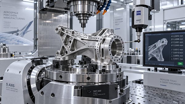
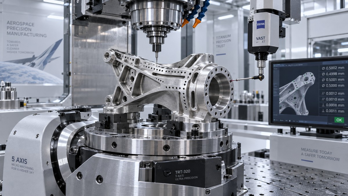
The direct answer is that micro machining aerospace tolerances can reach the low-micron range in production, but only on selected features with stable material, geometry, fixturing, tooling, thermal control, and metrology. A nominal tolerance such as ±5 µm may be repeatable on a short, accessible feature under a controlled process. Tolerances around ±1–3 µm are possible for certain specialized operations, but they should not be treated as a blanket capability for every feature on a complex aerospace part. The practical limit is defined by the whole production system, not by machine positioning resolution alone.
Separate machine resolution from production capability
A CNC machine may display sub-micron axis resolution, but resolution is not the same as delivered part tolerance. The finished dimension is affected by spindle runout, thermal drift, cutting force, tool wear, workholding movement, burr formation, material response, probing strategy, and uncertainty in the final measurement. A machine can command a very small move while the cutting process still produces a larger dimensional spread.
Quality teams should therefore ask a different question from “What tolerance can the machine hold?” The more useful question is: What tolerance can this supplier repeatedly demonstrate for this exact feature class, material condition, lot size, and inspection method? A micro-drilled hole in thin stainless steel, a narrow slot in titanium, and a precision sealing land in an aluminum alloy may all sit on the same part drawing, but they do not share the same achievable process window.
For production planning, it helps to view tolerance claims as feature-specific capability bands rather than universal shop limits.
Where tight micro tolerances usually fail
When an inspection result trends toward one side of tolerance, the cause is often not a single machine fault. The dimensional result may be changing gradually due to heat, or it may shift abruptly after a tool change, fixture release, or setup transfer. The pattern matters because it directs corrective action.
Thermal movement is often underestimated
Micro machining turns small physical changes into large quality consequences. Spindle warm-up, coolant temperature variation, room temperature changes, and heat generated at the cut can all move the tool, workpiece, or machine structure. A part measured immediately after machining may not match its stabilized condition. This becomes especially important when inspection is performed in a controlled environment but machining occurs under different thermal conditions.
For tight aerospace work, the routing should state when the part may be measured, what temperature conditions apply, and whether compensation is permitted. A dimensional correction based on one warm machine or one cold part can cause the next group of components to drift in the opposite direction.
Tool behavior dominates at micro scale
Small-diameter tools are sensitive to runout and radial load. Even slight eccentricity can cause one cutting edge to remove more material, accelerate wear, enlarge a hole, or leave an uneven wall condition. The issue is not limited to obvious breakage. Gradual edge degradation may first appear as increasing bore size, loss of corner definition, rising burr height, or a change in surface texture.
Tool-life management should be tied to the actual critical feature rather than only elapsed spindle time. A controlled process may require tool condition verification, presetting, runout checks at the holder assembly, and replacement limits before a feature approaches specification risk. When the drawing tolerance is only a few microns wide, “tool still cutting” is not an adequate acceptance criterion.
Fixturing can distort the feature being controlled
Thin aerospace sections and compliant parts can move under clamp load, vacuum force, or residual stress release. A dimension may appear correct while the part is restrained and shift after unclamping. The effect is particularly relevant around thin webs, pockets, skins, tabs, and parts machined from materials with locked-in stress.
Inspection planning must match the functional state of the component. If a part is measured in a condition that differs from its installed or free-state condition, a technically correct CMM result may still provide a misleading indication of functional fit. Fixture design, clamping sequence, machining order, and datum selection should be reviewed together rather than treated as separate activities.
Use the drawing to identify which tolerances are truly micro-machining risks
Not every tight number on an aerospace drawing carries the same manufacturing risk. A dimensional tolerance must be interpreted with its datum scheme, geometric control, surface requirement, material condition, and intended function. A ±5 µm size tolerance on a short, open diameter may be manageable, while a 5 µm positional tolerance on a deep hole pattern relative to multiple datums can be much more demanding.
Before approving a process route, review critical characteristics in terms of how they will be created and verified:
- Size: Is the feature a hole, width, thickness, radius, or external diameter? Can it be reached by a stable finishing tool?
- Location: Does the datum reference reflect how the part is fixtured during machining and assembled in service?
- Form: Are flatness, cylindricity, roundness, or profile controls tighter than the apparent size tolerance?
- Surface integrity: Could burrs, recast material, smeared metal, tensile residual stress, or tool marks affect function even when dimensions pass?
- Accessibility: Can both machining and inspection reach the feature without changing the relevant reference condition?
A useful warning sign is a drawing that combines a tiny tolerance with an undefined inspection method. A requirement is not fully production-ready merely because a number is present. The organization needs a clear way to establish the datum, collect the measurement, account for uncertainty, and decide conformity consistently.
Capability evidence should be reviewed before serial release
For safety-sensitive hardware, a first-off part that meets nominal dimensions is only an early indication. It does not demonstrate that the process will remain centered after repeated cycles, tooling changes, material lot variation, or routine operator handoffs. The evidence package should show how the process behaves, not just that one result was acceptable.
The scope of evidence should be proportionate to the characteristic’s risk. A practical review may include setup instructions, tool identification, in-process measurement points, first-piece approval records, inspection reports, and documented reaction plans. Where process capability analysis is required by the quality plan, it should be based on a measurement system suitable for the tolerance being evaluated. A capability index built on noisy or poorly aligned measurements can give false confidence.
Inspectors should also examine the distribution itself. A stable set of results close to a specification limit may pass every measured piece yet remain vulnerable to normal process movement. A more robust process is centered with usable margin on both sides. This distinction matters during transfer from pilot work to recurring production, where small changes in ambient conditions or material behavior become more visible.
Match measurement resolution and uncertainty to the requirement
At low-micron tolerances, inspection is part of the manufacturing process. Calipers, general-purpose optical systems, and standard CMM routines may not be appropriate for every feature. The choice depends on geometry and required uncertainty: air gauging may suit certain bores, vision measurement may help with delicate profiles, a form tester may be needed for roundness, and a carefully qualified CMM strategy may be suitable for location or profile.
The key issue is not simply selecting a highly accurate instrument. The measurement method must locate the same feature and datum condition intended by the drawing. Probe force can deflect thin sections. Optical edge detection can respond differently to surface finish or burrs. A stylus may not enter a small internal feature without introducing access limitations. Measurement-system analysis should address repeatability, reproducibility, fixturing, software alignment, operator method, and environmental effects.
A disciplined response when results begin to drift
When a micro feature moves toward a limit, avoid immediately changing offsets without understanding the pattern. Offset changes can temporarily restore a dimension while concealing tool wear, fixture movement, or thermal instability. Start by containing potentially affected parts according to the control plan, then compare results by time sequence, machine setup, tool identity, material batch, operator shift, and measurement station.
- Confirm the result with the approved inspection method and verify datum setup before treating the finding as a machining deviation.
- Determine whether the shift is gradual, stepwise, feature-specific, or present across multiple characteristics.
- Check tool condition, holder runout, spindle behavior, coolant delivery, and any recent tool or program changes.
- Review fixture contact points and clamp sequence for signs of movement, contamination, or part distortion.
- Compare part temperature and measurement timing with the validated process condition.
- Document the corrective action and verify that subsequent parts are stable, not merely returned to nominal once.
A stepwise shift immediately after a tool replacement suggests a different root cause from a slow drift across a shift. Likewise, a location error on several holes may point to datum transfer or fixture position, while a changing diameter on one micro bore more often points to tool behavior, heat, or chip evacuation. The corrective action should follow the observed signature.
When a tighter tolerance should trigger a process change
There is a point where asking for a smaller number should not result in tighter inspection alone. It should trigger a review of process architecture. The feature may need a dedicated finishing operation, a more rigid fixture, a shorter tool reach, controlled stock allowance, a different cutting strategy, or an alternative manufacturing method. In some cases, the functional requirement may be better expressed through geometric controls, surface condition, or an assembly-based acceptance criterion rather than an unnecessarily restrictive bilateral size tolerance.
This is particularly important when a tolerance was derived by dividing an assembly clearance without accounting for actual functional sensitivity, datum variation, thermal expansion, or downstream adjustment. Tightening a drawing requirement can raise scrap and inspection burden without improving flight performance. Conversely, relaxing a requirement without understanding fatigue, sealing, flow, or alignment consequences can create an unacceptable safety exposure.
The defensible approach is to connect each critical micro tolerance to function, then validate a production route that can create and measure it with margin. For aerospace micro machining, the lowest number a machine can occasionally demonstrate is not the relevant limit. The relevant limit is the smallest tolerance that remains controlled through normal production variation, verified by a measurement method capable of supporting a reliable acceptance decision.
Search News
Hot Articles
- Carbon Fiber StructuresHow to Specify Aerospace Carbon Fiber Assemblies for Lightweight, Load-Bearing PartsJul 11, 2026
- Machine VisionXiaomi, Alibaba DAMO Academy Drive Open-Source Robotics Model Ecosystem, Lowering Algorithm Development Barriers for Overseas SMEs Adopting Chinese Robotics SolutionsMar 30, 2026
- Cobots & ArmsShanxi 'AI+' Conference Showcases Embodied Intelligence with Multinational Buyer Engagement: Key Industry ImplicationsMar 30, 2026
Popular Tags
Recommended News
 Jul 11, 2026How to Specify Aerospace Carbon Fiber Assemblies for Lightweight, Load-Bearing PartsAerospace carbon fiber assemblies: learn how to specify laminate design, load data, joining methods, and inspection controls for lighter, reliable load-bearing aerospace parts.Elena Rostova (UAV Systems Researcher)
 Mar 30, 2026Xiaomi, Alibaba DAMO Academy Drive Open-Source Robotics Model Ecosystem, Lowering Algorithm Development Barriers for Overseas SMEs Adopting Chinese Robotics SolutionsXiaomi & Alibaba DAMO Academy's open-source robotics models lower algorithm barriers for global SMEs. Boost efficiency in manufacturing, logistics & smart retail with ROS 2 compatible solutions.TSV Data Lab
 Mar 30, 2026Shanxi 'AI+' Conference Showcases Embodied Intelligence with Multinational Buyer Engagement: Key Industry ImplicationsShanxi 'AI+' Conference highlights embodied intelligence with Tesla, Ubtech & Jiantao showcasing multimodal robotics. 40+ global buyers validated tech on-site, creating new B2B channels for industrial automation & AI solutions.Chen Wei (Automation Lead Engineer)
 Mar 30, 2026Zhongguancun Unveils 6G Integrated Sensing-Computing-Intelligence Platform to Empower Embodied Robots for Global Industrial ApplicationsZhongguancun's new 6G platform revolutionizes industrial robotics with <10ms latency, empowering global automotive, logistics & port automation. Discover how this tech boosts China's smart manufacturing exports.TSV Data Lab
 Mar 30, 2026Mech-Mind Tianjin Embodied Intelligence R&D and Production Base Goes Live, Cutting Delivery Time by 20%–30% for Global Customized AMR+Vision SolutionsMech-Mind's Tianjin AMR+Vision production base cuts delivery time by 20%-30% for欧美 & Latin American markets. Discover how this PLd-certified facility accelerates customized robotics solutions for smart manufacturing and logistics.Chen Wei (Automation Lead Engineer)
 Mar 30, 2026Boao Forum Reveals 'Co-evolution of Big and Small Brains' Trend in Humanoid Robots, China's Embodied Intelligence Accelerates Adaptation to Overseas Manufacturing Service ScenariosDiscover how China's humanoid robots, featuring 'Co-evolution of Big and Small Brains,' are revolutionizing global manufacturing. Learn about Embodied Tian Gong 3.0's ISO compliance and overseas deployment at Boao Forum 2026.Chen Wei (Automation Lead Engineer)
 Mar 30, 2026China Railway Industrial Secures Patent for Embodied Robotics in Material Handling, Boosting High-Precision Delivery Capabilities for Overseas Infrastructure and Manufacturing ProjectsChina Railway Industrial's new patent for embodied robotics in material handling boosts high-precision delivery for global infrastructure & manufacturing. Discover how this innovation enhances logistics accuracy in automotive, rail transit & EPC projects.Chen Wei (Automation Lead Engineer)
 Oct 14, 2026Drone Frame Composites: Carbon Fiber vs. Fiberglass for Weight and StiffnessExplore drone structural materials composites: compare carbon fiber and fiberglass for weight, stiffness, cost, and antenna compatibility. Find the right material for your drone frame.Elena Rostova (UAV Systems Researcher)
 Oct 13, 2026Smart Cameras vs. PC-Based Machine Vision: Which Fits High-Speed Inspection?This industrial product comparison for machine vision weighs smart cameras vs. PC-based systems on latency, throughput, and cost. Discover your best fit for high-speed inspection.TSV Data Lab
 Oct 12, 2026How to Verify RoHS Compliance in Industrial Sensing Systems Before DeploymentRoHS compliant sensing systems: learn how to verify materials, supplier declarations, testing, and configuration controls before industrial deployment.TSV Data Lab
 Oct 11, 2026How Procurement-Oriented Content Taxonomy Improves B2B Buying JourneysProcurement-oriented content taxonomy streamlines B2B buying journeys with clearer evidence, supplier comparisons, risk visibility, and faster approvals.TSV Data Lab
 Oct 10, 2026How to Select a Machine Performance Monitoring Platform for OEE and Downtime ReductionMachine performance monitoring platform selection guide: validate machine states, OEE data, downtime reasons, integrations, and scalability to reduce losses with confidence.TSV Data Lab
 Oct 08, 2026How to Machine Inconel 625 Blades Without Heat Cracks or Edge ChippingInconel 625 blade machining guide: prevent heat cracks, edge chipping, chatter, and work hardening with proven tooling, cooling, fixturing, and inspection strategies.Dr. Marcus Vance
 Oct 07, 2026How to Evaluate an HMI Panel Distributor for Industrial Automation ProjectsHMI panel distributor evaluation guide: verify technical compatibility, traceability, supply reliability, lifecycle support, and total cost for automation projects.Victor Lin (Chief Software Architect)
 Oct 06, 2026Navigation Fault Tolerance Standards for AMRs: What Safety Teams Must VerifyNavigation fault tolerance standards: learn what AMR safety teams must verify, from localization loss and sensor faults to stopping distance, safe restart, and site-specific validation.Chen Wei (Automation Lead Engineer)
 Oct 05, 2026Calculating Edge Computing Total Cost of Ownership Across Distributed SitesEdge computing ownership cost explained: calculate deployment, energy, connectivity, security, remote support, and refresh costs across distributed sites.TSV Data Lab
 Oct 04, 2026CAD/CAM Benchmarking in the GCC: What Manufacturers Should Ask a ConsultantCAD CAM benchmark consultant GCC guide: learn the key questions manufacturers should ask to validate post-processors, workflows, machine performance, and production risk.Victor Lin (Chief Software Architect)
 Oct 03, 2026Selecting Automotive Radar Sensor Modules for ADAS Range, Resolution, and IntegrationAutomotive radar sensor module selection guide for ADAS: compare range, resolution, field of view, latency, and integration to build safer, reliable vehicle systems.TSV Data Lab
 Oct 02, 2026How to Qualify Machined Parts Suppliers for Hard Tech ProgramsHard tech supply chain machined parts demand rigorous supplier qualification. Learn how to assess capability, traceability, quality controls, and delivery resilience.Dr. Marcus Vance
 Oct 01, 2026How to Select an Outdoor Security Radar Sensor for Perimeter Detection?Outdoor security radar sensor selection guide: compare range, accuracy, false-alarm control, integration, and field testing for reliable perimeter detection.TSV Data Lab
 Sep 30, 2026How to Evaluate Solid-State LiDAR Hardware for Outdoor Autonomous VehiclesSolid state LiDAR hardware evaluation guide for outdoor autonomous vehicles—compare range, point-cloud quality, environmental resilience, integration, and safety.TSV Data Lab
 Sep 29, 2026ISO 9283 Repeatability: How to Evaluate Cobot Positioning PerformanceISO 9283 cobot repeatability explained: learn how payload, reach, approach direction, and test conditions affect positioning performance and cell capability.Chen Wei (Automation Lead Engineer)
 Oct 14, 2026How tight can micro machining aerospace tolerances be in production?Micro machining aerospace tolerances can reach low-micron levels in production. Learn what controls repeatability, inspection confidence, and flight-critical quality.Dr. Marcus Vance
 Oct 13, 2026How to keep an industrial robotic integration project on scheduleIndustrial robotic integration project management: keep automation on schedule with proven controls for interfaces, suppliers, FAT, commissioning, and change risk.Victor Lin (Chief Software Architect)