Cobot for CNC Machine Tending: What Limits Cycle Time Gains?
Publication Date
author
For manufacturers evaluating a cobot for CNC machine tending, cycle time gains rarely depend on robot speed alone. They are constrained by part presentation, chucking consistency, servo drive response time, robotic arm vibration analysis, and the wider smart factory automation solutions stack. This article examines the real bottlenecks engineers, buyers, and decision-makers must benchmark before expecting meaningful throughput improvements.
In practice, many teams overestimate the impact of catalog robot speed and underestimate the losses hidden in machine readiness, gripper changeover, unstable workholding, and data handshakes between the CNC, robot controller, and factory systems. A cobot can reduce idle labor, extend unattended hours, and improve consistency, but it does not automatically compress the full machining cycle.
For operators, the question is whether loading becomes smoother and safer. For procurement teams, the concern is whether the automation cell delivers measurable throughput within a 12- to 24-month payback window. For enterprise decision-makers, the issue is broader: can a cobot machine tending project scale across multiple CNC assets without creating new bottlenecks elsewhere in the production line?
Where Cycle Time Is Really Won or Lost
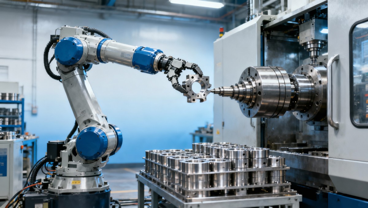
A CNC machine tending cell consists of at least 5 time blocks: door open and close, part unload, part transfer, fresh part load, and machine restart confirmation. If the cutting cycle is 180 seconds and robotic handling consumes 22 seconds, reducing robot motion by 3 seconds only improves the total cycle by about 1.5%. That is useful, but rarely transformative.
The larger gains often come from removing uncertainty. If parts arrive misoriented, if the chuck requires a second seating attempt, or if the machine waits 4 to 6 seconds for a permissive signal, the robot’s nominal repeatability is not the root issue. In many cells, interface delays and fixture inconsistency outweigh pure arm motion time.
This is why serious benchmarking should separate machining time from non-cut time. A cobot for CNC machine tending may improve spindle utilization from 62% to 78%, yet the improvement can stall if upstream kitting, tray replenishment, or in-process gauging is not aligned. Throughput depends on the entire automation loop, not a single axis speed value.
The Five Hidden Constraints
- Part presentation accuracy: inconsistent orientation can add 2 to 8 seconds per cycle.
- Chucking consistency: a poor seating condition may trigger re-grip, blow-off, or operator intervention.
- Servo and I/O latency: handshake delays of 300 to 800 milliseconds across several steps become material.
- Arm vibration and settle time: longer reaches and heavier grippers can require 0.4 to 1.2 seconds of stabilization.
- Machine-side readiness: slow door actuation, coolant splash clearing, or confirmation alarms may dominate the wait state.
For TSV-style evaluation, the practical metric is not maximum robot speed in isolation. It is effective non-cut exchange time under stable production conditions over a sample of at least 300 to 500 cycles. That measurement reveals whether the cell is truly repeatable or only fast during demonstrations.
A Baseline Comparison Framework
Before approving a cobot cell, teams should compare current manual tending, assisted loading, and full robotic tending on the same part family. The table below provides a practical structure for that review.
The key conclusion is simple: a cobot for CNC machine tending usually creates the best result when labor variability is high, machine cycles exceed 90 seconds, and parts can be presented within a predictable window. If machining cycles are only 20 to 40 seconds, every delay in loading logic becomes magnified.
Part Presentation, Workholding, and Machine Interface Delays
Part presentation is frequently the first overlooked constraint. A robot can repeat a programmed pose within a narrow range, but if raw blanks arrive with orientation drift of 1.5 to 3.0 mm, the gripper may compensate poorly. This is especially relevant in turned parts, cast near-net blanks, and oily components stacked in bins without dedicated nests.
Workholding is the second major limiter. Many cycle time studies assume the chuck or vise accepts parts with perfect seating on the first attempt. In reality, chip residue, jaw wear, or dimensional variation can create a second insertion or a short dwell before clamping confirmation. A 2-second delay repeated 1,000 times per shift becomes 33 minutes of lost machine availability.
Machine interface timing matters just as much. Some CNCs still rely on relay-based handshakes or legacy PLC logic that adds several discrete waits: door unlocked, spindle stopped, chuck open, part present, clamp confirmed, and cycle start accepted. Even if each state costs only 0.4 seconds, 6 to 8 states create a meaningful drag on output.
Typical Delay Sources in CNC Tending Cells
A reliable automation project maps every delay source instead of blaming the robot alone. The table below lists common bottlenecks and realistic engineering responses.
For buyers, the practical takeaway is to request a cycle decomposition, not a single headline number. A supplier should show robot motion time, machine wait time, clamp verification time, and fault recovery behavior separately. Without that granularity, a promised 15% throughput gain can be impossible to validate.
What Operators Should Validate During Trial Runs
- Run at least 50 consecutive parts from real production stock, not hand-selected samples.
- Check whether chuck seating remains stable after coolant and chip accumulation.
- Measure false-stop frequency per 100 cycles and document the exact root cause.
- Verify that door motion, spindle stop confirmation, and clamp signals are synchronized without added waits.
These checks matter because the most expensive lost time is not a slow robot move. It is a cell that pauses every 40 or 60 parts due to an avoidable interface or fixturing issue. Stable automation is usually more valuable than marginally faster motion.
Servo Response, Arm Dynamics, and Vibration Limits
When a cobot is asked to tend a CNC machine, dynamic behavior becomes more important than brochure speed. The same arm that performs well with a 1 kg gripper may behave differently with a 4 kg dual gripper, a long finger set, and a 300 mm offset center of mass. The result can be longer settle time before placement or slower acceleration imposed by safety parameters.
Servo drive response time is part of this equation. If the arm decelerates conservatively to avoid overshoot, each pick-and-place segment can lose fractions of a second. Over 6 to 10 motion segments per cycle, those fractions accumulate. In high-mix machining cells, the effect is amplified when recipes change frequently and each part family uses a different path or grip profile.
Robotic arm vibration analysis is therefore not academic. Long reaches, pedestal mounting, flexible floor anchoring, and rapid wrist reorientation can cause small oscillations that require the controller to wait before confirming stable placement. A settle delay of 0.7 seconds may be acceptable on a 12-minute aerospace machining cycle, but it is significant on a 75-second production cycle.
Engineering Factors That Affect Motion Efficiency
- Payload utilization above 60% of rated capacity usually reduces practical acceleration.
- Extended gripper fingers can increase deflection and reduce insertion confidence.
- Pedestal height and cantilever geometry influence vibration more than many teams expect.
- Safety zones, collaborative speed limits, and nearby operator traffic may cap actual travel speed well below nominal values.
From a procurement perspective, ask for tested cycle time at your target payload, not at the robot’s empty-arm speed. Also request information on path repeatability under process conditions, especially if the cell includes vision correction, double-grip handling, or machine-to-machine transfer. The installed performance can differ markedly from laboratory values.
Recommended Benchmark Metrics for Dynamic Performance
A structured validation method helps separate usable performance from theoretical specifications. The benchmarks below are practical for engineering review.
This table shows why the best cobot for CNC machine tending is not always the one with the highest stated top speed. The more relevant machine tending metric is stable exchange time under the real payload, real safety settings, and real floor conditions used in production.
Why the Wider Automation Stack Determines Throughput
A cobot cell does not operate in isolation. It depends on sensors, machine vision where needed, edge I/O devices, safety relays, HMIs, and often a manufacturing execution or monitoring layer. If any link in that chain is slow, unreliable, or poorly integrated, the expected cycle time gains shrink quickly.
For example, a machine vision check that adds 1.2 seconds may still be justified if it prevents a 1 in 200 misload event that causes spindle damage or scrap. By contrast, a slow data exchange between the CNC and robot controller that adds 0.5 seconds to every cycle may never pay back. Good smart factory automation solutions reduce systemic friction instead of simply adding more components.
This systems view is particularly important for multi-machine tending. One cobot may service 2 or 3 CNCs, but only if queueing logic, part buffers, and machine cycle variability are tightly controlled. If one machine’s actual cycle drifts by 10% to 15%, the robot schedule can break down, creating waiting states across the cell.
Integration Questions Buyers Should Ask
- How many discrete signal states are required between robot and CNC for a complete load-unload cycle?
- Is the cell designed for single-part flow, tray buffering, pallet buffering, or mixed part families?
- Can fault codes be logged by event type, timestamp, and machine source for root-cause review?
- How long does recipe changeover take: 5 minutes, 20 minutes, or a full hour with reteaching?
These questions matter because a machine tending investment succeeds when it combines mechanical stability with operational transparency. A cell that saves 12 seconds but lacks usable diagnostics may cost more in troubleshooting than it returns in throughput. Conversely, a slightly slower but better-instrumented cell can scale more effectively across a factory network.
Implementation Priorities for Real-World Deployment
- Map baseline OEE, spindle utilization, and non-cut exchange time before installation.
- Standardize raw part presentation and finished-part placement to reduce operator refill errors.
- Build event logging around top 5 stop causes during the first 30 days of operation.
- Plan preventive checks for gripper wear, chuck cleanliness, and signal timing drift every week.
For enterprises considering rollouts across several sites, the procurement specification should include interface architecture, fault taxonomy, cycle study method, and acceptance testing criteria. That data-first approach aligns with TSV’s broader principle: engineering truth comes from measured performance, not marketing labels.
Selection Criteria, Common Mistakes, and a Practical Buying Checklist
Selecting a cobot for CNC machine tending should start with the part, not the robot. Weight, surface finish, oil contamination, tolerance sensitivity, and required insertion accuracy determine the gripping method and workholding strategy. Only after those are defined does arm reach, payload, and controller capability become meaningful.
A common mistake is assuming the cell that wins a showroom demo will also win on the shop floor. Demo parts are often dry, clean, dimensionally stable, and ideal for gripping. Production parts may vary from batch to batch, arrive warm from upstream processing, or carry chips and coolant that change friction behavior. Those conditions should be part of the acceptance test.
Another mistake is focusing on robot ROI while ignoring the supporting hardware. A gripper upgrade, chuck sensor retrofit, tray redesign, or air blast add-on may each cost far less than the robot itself, yet they often determine whether the system saves 5% or 20% in total handling time. Buyers should budget for the full cell, not only the arm.
Practical Buying Checklist
The checklist above helps procurement teams compare integrators and equipment packages on measurable factors. It also reduces the risk of approving a system based on one impressive video rather than verified production readiness.
FAQ for Engineers and Buyers
How much cycle time improvement is realistic?
In many CNC tending applications, the most realistic gain comes from increasing machine utilization and reducing labor dependency rather than cutting seconds from pure handling motion. If machining cycles are longer than 2 to 3 minutes, unattended operation can create larger output gains than motion optimization alone.
When does a cobot struggle to deliver value?
Short-cycle jobs under about 45 seconds, unstable raw part presentation, and frequent part-family changeovers can limit payback unless fixtures, trays, and interfaces are carefully engineered. In those cases, the problem is usually process variability, not the robot itself.
Which metric matters most during acceptance?
Look at repeatable non-cut exchange time together with stop frequency per 100 cycles. A cell that is 2 seconds slower but runs 500 cycles without intervention often outperforms a faster cell that faults every 40 cycles.
Cycle time gains from a cobot for CNC machine tending are constrained less by headline robot speed than by part presentation discipline, workholding repeatability, interface latency, arm dynamics, and the quality of the surrounding automation stack. For manufacturers, that means the right buying decision begins with measured bottlenecks, not broad automation claims.
TechStat Vanguard’s engineering-first lens is simple: benchmark what actually governs throughput, define acceptance criteria in data, and evaluate every supplier against the same operational truth. If you are planning a machine tending project, optimizing an existing cell, or drafting a procurement specification, now is the right time to get a more rigorous view of cycle-time limits and scalable automation design.
Contact us to discuss your CNC tending scenario, request a structured evaluation framework, or explore a data-driven automation roadmap built around real production constraints.
Search News
Hot Articles
- Carbon Fiber StructuresHow to Specify Aerospace Carbon Fiber Assemblies for Lightweight, Load-Bearing PartsJul 11, 2026
- Machine VisionXiaomi, Alibaba DAMO Academy Drive Open-Source Robotics Model Ecosystem, Lowering Algorithm Development Barriers for Overseas SMEs Adopting Chinese Robotics SolutionsMar 30, 2026
- Cobots & ArmsShanxi 'AI+' Conference Showcases Embodied Intelligence with Multinational Buyer Engagement: Key Industry ImplicationsMar 30, 2026
Popular Tags
Recommended News
 Jul 11, 2026How to Specify Aerospace Carbon Fiber Assemblies for Lightweight, Load-Bearing PartsAerospace carbon fiber assemblies: learn how to specify laminate design, load data, joining methods, and inspection controls for lighter, reliable load-bearing aerospace parts.Elena Rostova (UAV Systems Researcher)
 Mar 30, 2026Xiaomi, Alibaba DAMO Academy Drive Open-Source Robotics Model Ecosystem, Lowering Algorithm Development Barriers for Overseas SMEs Adopting Chinese Robotics SolutionsXiaomi & Alibaba DAMO Academy's open-source robotics models lower algorithm barriers for global SMEs. Boost efficiency in manufacturing, logistics & smart retail with ROS 2 compatible solutions.TSV Data Lab
 Mar 30, 2026Shanxi 'AI+' Conference Showcases Embodied Intelligence with Multinational Buyer Engagement: Key Industry ImplicationsShanxi 'AI+' Conference highlights embodied intelligence with Tesla, Ubtech & Jiantao showcasing multimodal robotics. 40+ global buyers validated tech on-site, creating new B2B channels for industrial automation & AI solutions.Chen Wei (Automation Lead Engineer)
 Mar 30, 2026Zhongguancun Unveils 6G Integrated Sensing-Computing-Intelligence Platform to Empower Embodied Robots for Global Industrial ApplicationsZhongguancun's new 6G platform revolutionizes industrial robotics with <10ms latency, empowering global automotive, logistics & port automation. Discover how this tech boosts China's smart manufacturing exports.TSV Data Lab
 Mar 30, 2026Mech-Mind Tianjin Embodied Intelligence R&D and Production Base Goes Live, Cutting Delivery Time by 20%–30% for Global Customized AMR+Vision SolutionsMech-Mind's Tianjin AMR+Vision production base cuts delivery time by 20%-30% for欧美 & Latin American markets. Discover how this PLd-certified facility accelerates customized robotics solutions for smart manufacturing and logistics.Chen Wei (Automation Lead Engineer)
 Mar 30, 2026Boao Forum Reveals 'Co-evolution of Big and Small Brains' Trend in Humanoid Robots, China's Embodied Intelligence Accelerates Adaptation to Overseas Manufacturing Service ScenariosDiscover how China's humanoid robots, featuring 'Co-evolution of Big and Small Brains,' are revolutionizing global manufacturing. Learn about Embodied Tian Gong 3.0's ISO compliance and overseas deployment at Boao Forum 2026.Chen Wei (Automation Lead Engineer)
 Mar 30, 2026China Railway Industrial Secures Patent for Embodied Robotics in Material Handling, Boosting High-Precision Delivery Capabilities for Overseas Infrastructure and Manufacturing ProjectsChina Railway Industrial's new patent for embodied robotics in material handling boosts high-precision delivery for global infrastructure & manufacturing. Discover how this innovation enhances logistics accuracy in automotive, rail transit & EPC projects.Chen Wei (Automation Lead Engineer)
 Oct 15, 2026R&D Cost Reduction Services: How to Evaluate Fees, Savings, and ROIEvaluate R&D cost reduction services with confidence. Compare fees, verify savings, and calculate ROI without compromising performance. Discover how to choose a provider that delivers real value.Chen Wei (Automation Lead Engineer)
 Oct 14, 2026Drone Frame Composites: Carbon Fiber vs. Fiberglass for Weight and StiffnessExplore drone structural materials composites: compare carbon fiber and fiberglass for weight, stiffness, cost, and antenna compatibility. Find the right material for your drone frame.Elena Rostova (UAV Systems Researcher)
 Oct 13, 2026Smart Cameras vs. PC-Based Machine Vision: Which Fits High-Speed Inspection?This industrial product comparison for machine vision weighs smart cameras vs. PC-based systems on latency, throughput, and cost. Discover your best fit for high-speed inspection.TSV Data Lab
 Oct 12, 2026How to Verify RoHS Compliance in Industrial Sensing Systems Before DeploymentRoHS compliant sensing systems: learn how to verify materials, supplier declarations, testing, and configuration controls before industrial deployment.TSV Data Lab
 Oct 11, 2026How Procurement-Oriented Content Taxonomy Improves B2B Buying JourneysProcurement-oriented content taxonomy streamlines B2B buying journeys with clearer evidence, supplier comparisons, risk visibility, and faster approvals.TSV Data Lab
 Oct 10, 2026How to Select a Machine Performance Monitoring Platform for OEE and Downtime ReductionMachine performance monitoring platform selection guide: validate machine states, OEE data, downtime reasons, integrations, and scalability to reduce losses with confidence.TSV Data Lab
 Oct 08, 2026How to Machine Inconel 625 Blades Without Heat Cracks or Edge ChippingInconel 625 blade machining guide: prevent heat cracks, edge chipping, chatter, and work hardening with proven tooling, cooling, fixturing, and inspection strategies.Dr. Marcus Vance
 Oct 07, 2026How to Evaluate an HMI Panel Distributor for Industrial Automation ProjectsHMI panel distributor evaluation guide: verify technical compatibility, traceability, supply reliability, lifecycle support, and total cost for automation projects.Victor Lin (Chief Software Architect)
 Oct 06, 2026Navigation Fault Tolerance Standards for AMRs: What Safety Teams Must VerifyNavigation fault tolerance standards: learn what AMR safety teams must verify, from localization loss and sensor faults to stopping distance, safe restart, and site-specific validation.Chen Wei (Automation Lead Engineer)
 Oct 05, 2026Calculating Edge Computing Total Cost of Ownership Across Distributed SitesEdge computing ownership cost explained: calculate deployment, energy, connectivity, security, remote support, and refresh costs across distributed sites.TSV Data Lab
 Oct 04, 2026CAD/CAM Benchmarking in the GCC: What Manufacturers Should Ask a ConsultantCAD CAM benchmark consultant GCC guide: learn the key questions manufacturers should ask to validate post-processors, workflows, machine performance, and production risk.Victor Lin (Chief Software Architect)
 Oct 03, 2026Selecting Automotive Radar Sensor Modules for ADAS Range, Resolution, and IntegrationAutomotive radar sensor module selection guide for ADAS: compare range, resolution, field of view, latency, and integration to build safer, reliable vehicle systems.TSV Data Lab
 Oct 02, 2026How to Qualify Machined Parts Suppliers for Hard Tech ProgramsHard tech supply chain machined parts demand rigorous supplier qualification. Learn how to assess capability, traceability, quality controls, and delivery resilience.Dr. Marcus Vance
 Oct 01, 2026How to Select an Outdoor Security Radar Sensor for Perimeter Detection?Outdoor security radar sensor selection guide: compare range, accuracy, false-alarm control, integration, and field testing for reliable perimeter detection.TSV Data Lab
 Sep 30, 2026How to Evaluate Solid-State LiDAR Hardware for Outdoor Autonomous VehiclesSolid state LiDAR hardware evaluation guide for outdoor autonomous vehicles—compare range, point-cloud quality, environmental resilience, integration, and safety.TSV Data Lab
 Sep 29, 2026ISO 9283 Repeatability: How to Evaluate Cobot Positioning PerformanceISO 9283 cobot repeatability explained: learn how payload, reach, approach direction, and test conditions affect positioning performance and cell capability.Chen Wei (Automation Lead Engineer)
 Oct 14, 2026How tight can micro machining aerospace tolerances be in production?Micro machining aerospace tolerances can reach low-micron levels in production. Learn what controls repeatability, inspection confidence, and flight-critical quality.Dr. Marcus Vance