How floor conditions affect AGV positioning accuracy
Publication Date
author
Floor conditions directly influence agv positioning accuracy millimeter performance, affecting navigation stability, stopping repeatability, and overall system safety. From flatness deviation and joint gaps to dust, vibration, and reflective surfaces, even minor floor defects can distort sensor feedback and localization results. This article explains how floor variables impact AGV accuracy and what engineers, operators, and buyers should evaluate before deployment.
Why floor conditions matter more than many AGV projects expect
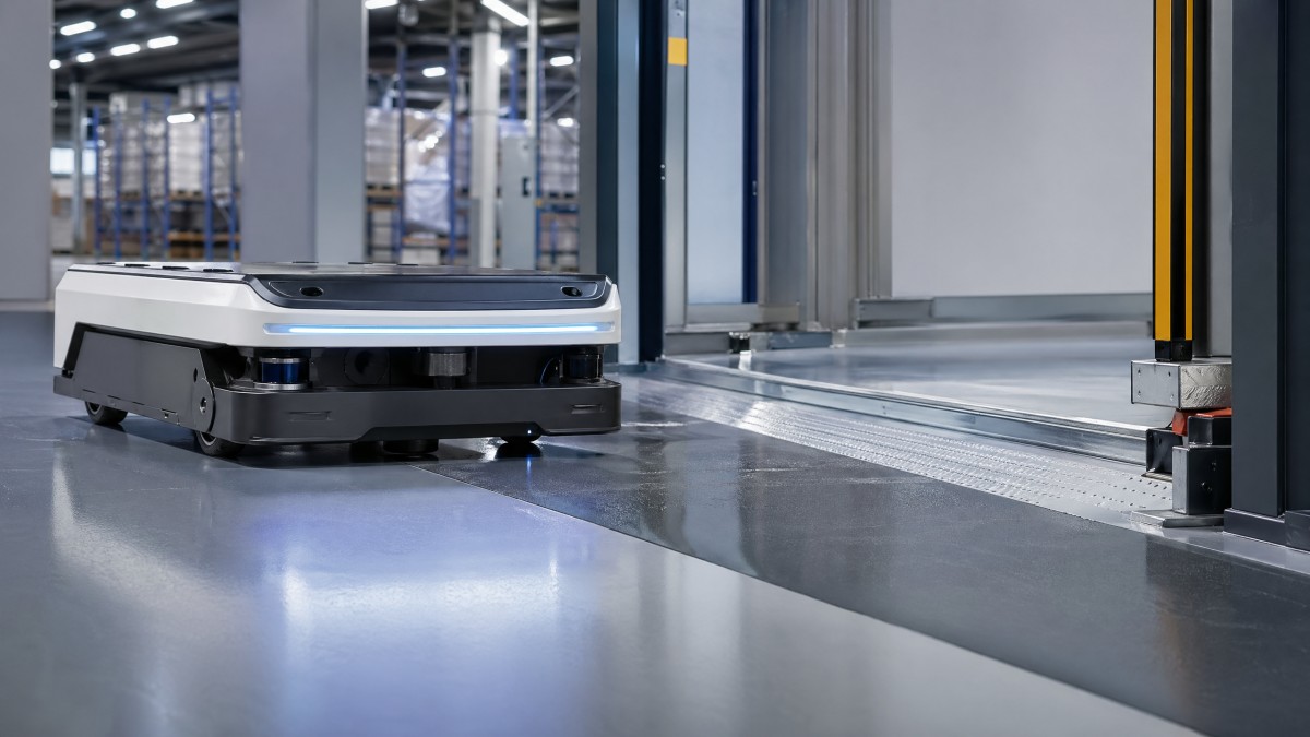
In AGV and AMR deployments, positioning accuracy is often discussed as a vehicle specification, but in real factories and warehouses it is a system-level outcome. A vehicle rated for ±5 mm to ±10 mm repeatability under controlled test conditions may not achieve the same result on a floor with slope variation, cracks, patched areas, or unstable reflectivity. This gap between brochure values and operating reality is one of the most common reasons projects underperform after commissioning.
For operators, poor floor quality shows up as missed docking, uneven pallet pickup, slower speed at intersections, and frequent correction movements. For procurement teams, it creates a hidden cost because the same AGV model may require extra sensors, tighter infrastructure work, or longer commissioning cycles in one site than another. For decision-makers, the issue is strategic: floor conditions affect throughput, safety margin, and long-term maintenance burden.
TechStat Vanguard evaluates AGV positioning accuracy through an engineering lens rather than marketing language. That means asking practical questions: what floor flatness range is acceptable, how wide are the expansion joints, what contamination appears per shift, and how much vibration enters the sensor stack during loaded travel. Parameters do not lie; tolerances dictate success. In AGV projects, the floor is not background infrastructure. It is part of the navigation system.
A useful way to frame the problem is to separate three accuracy targets. First is path tracking accuracy during movement. Second is stopping repeatability at transfer points. Third is localization stability over time, especially across 8-hour, 16-hour, or 24-hour operating schedules. Different floor defects influence each target differently, so site surveys should not stop at a simple visual inspection.
Three floor-related mechanisms that reduce positioning accuracy
- Geometric disturbance: flatness deviation, local slope, potholes, and joint gaps change vehicle posture, wheel contact, and encoder interpretation.
- Surface condition disturbance: dust, oil film, water, worn paint, and reflective patches interfere with traction and optical sensing.
- Dynamic disturbance: vibration from adjacent machinery, forklift traffic, or suspended slabs introduces localization noise and intermittent correction behavior.
When these three mechanisms stack together, even a well-configured AGV can appear inconsistent. The problem is not always the controller, the LiDAR, or the mapping algorithm. Very often, the floor creates multiple small errors that accumulate over a 20 m, 50 m, or 100 m route until the vehicle arrives off-position at the final station.
Which floor variables most strongly affect AGV positioning accuracy?
Not all floor imperfections have the same impact. Some primarily reduce travel comfort, while others directly disturb localization and stopping precision. For example, a cosmetic stain may have little consequence for a magnetic-guided AGV but can affect camera-based navigation if it changes contrast or glare. A 3 mm to 8 mm joint gap may be manageable for a heavy vehicle with large wheels, yet it can still create a measurable pose shift during docking.
The table below summarizes common floor variables and the type of positioning risk they create. These are not universal pass-fail numbers, because acceptable tolerance depends on vehicle mass, wheel diameter, suspension design, navigation method, and target stopping accuracy. However, the categories provide a practical framework for cross-functional review before procurement or acceptance.
For B2B buyers, this table helps separate visible defects from performance-critical defects. A floor that looks acceptable to general facilities teams may still be unsuitable for precision handoff between AGV and conveyor, AGV and robot, or AGV and storage rack. That is why site surveys should translate floor observations into positioning risk, not just maintenance notes.
How different navigation methods react to floor conditions
Magnetic guidance, QR code guidance, natural feature navigation, SLAM-based LiDAR navigation, and vision navigation all depend on floor quality in different ways. Magnetic systems are relatively tolerant of lighting changes but still suffer from traction loss and mechanical disturbance. QR code systems rely heavily on code readability and floor marking integrity. LiDAR and visual systems may ignore some paint damage yet become sensitive to reflective clutter or repeated pose disturbances caused by uneven surfaces.
In practice, no mainstream navigation method is independent from floor quality. Even when localization is robust, braking distance and final alignment still depend on stable wheel-floor interaction. If the application demands pallet engagement, charging dock contact, or machine loading with repeatability in the low-millimeter range, floor engineering becomes part of the navigation design package.
A practical rule is to evaluate floor effects at three route zones: long travel corridors, turning zones, and critical stations. The last zone usually deserves the strictest review because a small pitch change over the final 1 m to 2 m can produce larger vertical or horizontal mismatch at the interface point than the same defect would produce in open travel.
Four checks engineers should complete before deployment
- Measure representative floor flatness along at least the main route, the turning zones, and all docking stations rather than checking only one reference area.
- Record joint width, height difference, and patch transitions that repeat every 5 m to 20 m, because recurring shocks often create systematic error patterns.
- Observe contamination by shift and by season, especially in facilities with water ingress, coolant exposure, or outdoor-to-indoor traffic.
- Compare floor findings with the AGV supplier’s acceptance criteria for wheel type, payload class, and required stopping repeatability.
What should buyers and project teams evaluate before selecting an AGV solution?
A common procurement mistake is to compare AGVs only by payload, speed, battery runtime, and software features while treating the floor as a separate civil issue. In reality, floor condition can change the total project cost, commissioning time, and feasibility of a chosen navigation stack. A lower-priced vehicle may become more expensive if it needs route resurfacing, added markers, slower operating speed, or repeated tuning after go-live.
Buyers should align three things early: the target positioning accuracy, the real floor condition, and the process interface. If the process only needs coarse transport over 30 m to 80 m, the floor tolerance window may be broader. If the process includes automatic docking, robotic transfer, or narrow rack alignment, the site may require tighter floor preparation within the final 1 m to 3 m around each station.
The procurement discussion should also include lifecycle factors. Floors change over time. Expansion joints widen, coatings wear, and forklift impact accumulates. A system that works on day 1 may drift outside acceptable repeatability after 6 to 12 months if preventive floor maintenance is not defined in the handover scope. This is where data-driven supplier evaluation matters more than generic claims.
The table below can be used as a practical AGV positioning accuracy procurement checklist. It helps information researchers, operators, and decision-makers translate technical risk into comparison points during RFQ and FAT or SAT planning.
This checklist is especially useful when multiple departments are involved. Facilities teams focus on floor repair scope, automation engineers focus on repeatability, procurement compares supplier risk, and management evaluates total implementation time. A shared matrix reduces ambiguity and shortens the supplier qualification cycle by forcing concrete answers instead of vague assurance.
A practical 4-step evaluation workflow
Step 1 is route classification. Separate bulk transport paths from precision interface stations. Step 2 is floor measurement and contamination review. Step 3 is supplier matching based on navigation method, wheel configuration, and required docking repeatability. Step 4 is on-site validation with loaded and unloaded runs, ideally across multiple cycles such as 20, 50, or 100 repetitions depending on process criticality.
This workflow matters because a route can be broadly acceptable while one single charging point or one conveyor transfer station fails repeatedly. Precision manufacturing and advanced logistics projects often succeed or fail at the interface, not on the corridor. That is also why TechStat Vanguard emphasizes engineering benchmarks and traceable parameter review instead of feature-based vendor comparison alone.
Where internal teams lack comparable field data, a third-party-style benchmarking mindset helps. The right question is not whether a vehicle is marketed as accurate, but under which floor and load conditions that accuracy is sustained. This distinction protects budgets and avoids redesign late in the project.
How to improve positioning accuracy when the floor is already imperfect
Many facilities cannot shut down operations for full resurfacing. In those cases, the goal is to rank defects by performance impact and correct the most critical zones first. The highest priority is usually the final docking area, charging points, lift entrances, and any handoff location where a few millimeters of offset can stop production. Improvement does not always require full reconstruction, but it does require disciplined engineering trade-offs.
One effective approach is zone-based remediation. Instead of treating all 5,000 m² or 20,000 m² equally, teams can upgrade only the last 2 m to 5 m near key stations, smooth problematic joints on turning paths, and enforce tighter cleaning schedules on routes where traction-sensitive braking occurs. This targeted method often delivers better return than uniform cosmetic repair across low-risk travel areas.
Another option is solution matching. Larger wheels, adjusted suspension characteristics, alternative sensor fusion strategies, and station-level correction logic can improve tolerance to real-world floor variability. However, these measures should not be used to excuse severe floor defects. A system can compensate for limited disturbance; it cannot erase persistent geometric instability without cost in speed, reliability, or maintenance.
For mixed-use sites with forklifts, pedestrians, and AGVs operating over 2 or 3 shifts, preventive floor governance is just as important as initial commissioning. Small defects often grow slowly and then suddenly cause repeated docking alarms. Regular review every month or every quarter can catch this drift before it affects throughput.
Priority actions that usually deliver the fastest improvement
- Repair height transitions and cracked edges at docking points before adjusting software parameters, because hardware instability often looks like a control issue.
- Define cleaning frequency by route risk, for example once per shift for oily zones and weekly inspection for low-contamination corridors.
- Validate loaded braking and stopping under normal operating mass, not only in no-load testing, because traction behavior changes materially with payload.
- Create a floor defect escalation threshold so maintenance teams know when a 2 mm, 5 mm, or larger change requires intervention.
Common misconceptions that delay improvement
The first misconception is that software mapping alone can solve floor-induced accuracy loss. Mapping can improve localization confidence, but it does not remove slip, bounce, or mechanical pose change. The second misconception is that only old floors cause problems. Even new facilities can create AGV issues if coatings are glossy, joints are poorly finished, or utility trench covers introduce local deflection.
The third misconception is that route speed should be reduced everywhere. Lower speed can help at critical points, but a blanket reduction across the site may hide the real root cause while reducing productivity. Better practice is selective tuning: fix high-impact floor zones, optimize station approach logic, and verify repeatability over defined cycle counts.
A final misconception is that the floor is only a facilities concern. In advanced automation, floor condition is a shared responsibility across engineering, operations, procurement, and maintenance. Treating it as a separate issue often leads to longer launch periods and avoidable cost escalation.
FAQ for engineers, operators, and procurement teams
Can an AGV still achieve high positioning accuracy on an imperfect floor?
Yes, but the answer depends on how imperfect the floor is and where the defects are located. Broad transport routes may tolerate more variation than docking or machine-loading points. In many projects, acceptable performance is possible if the critical final approach zone is corrected, traction is stable, and the navigation method is matched to the environment. The key is to define the required accuracy at each station rather than asking for one blanket number across the whole plant.
Which floor defect is usually most damaging to AGV positioning accuracy?
There is no single universal answer, but three categories repeatedly create the most trouble: vertical discontinuities at joints or patches, low-traction contamination such as oil or moisture, and reflective or low-feature zones that degrade optical localization. In precision transfer applications, a small but repeated joint shock near the final station can be more harmful than a larger defect located far away on an open corridor.
What should be included in AGV site acceptance related to floors?
A robust acceptance plan should include at least 4 elements: route condition verification, loaded and unloaded repeatability checks, station-by-station stopping evaluation, and documented recovery behavior after minor disturbance or slip. Where applications are critical, teams often add repeated cycle tests over 20 to 100 runs and confirm results across more than one shift to account for changing contamination and traffic conditions.
How early should floor assessment start in procurement?
Ideally at the pre-RFQ stage. If floor facts are known early, suppliers can recommend the right navigation method, wheel package, and station design before pricing is finalized. If assessment starts after supplier selection, the project may face redesign, civil rework, or longer commissioning. Early floor review is one of the simplest ways to reduce trial-and-error cost and shorten qualification cycles.
Why choose a data-driven evaluation partner for AGV floor and positioning analysis
When AGV positioning accuracy becomes a purchasing or deployment bottleneck, generic vendor claims are not enough. Teams need a clear translation between floor conditions, navigation architecture, stopping repeatability, and lifecycle risk. That is where TechStat Vanguard brings value. Our approach is built around engineering truth through data: parameter review, benchmark-style comparison, and practical interpretation for R&D engineers, procurement leaders, and operational stakeholders.
Instead of asking buyers to trust broad descriptions, we focus on measurable decision inputs. That includes route condition mapping, tolerance-focused comparison logic, floor-to-sensor interaction analysis, and implementation questions that reduce ambiguity before supplier commitment. In hard-tech procurement, this discipline helps cut information noise and supports more defensible decisions across automation, sensors, and precision industrial systems.
If you are evaluating AGV projects, refining a spec sheet, or troubleshooting why expected repeatability is not being achieved on site, the most useful next step is a structured technical review. Typical consultation topics include floor tolerance confirmation, navigation method comparison, station-level docking requirements, delivery and commissioning checkpoints, maintenance criteria, and risk prioritization for existing facilities.
Contact TechStat Vanguard to discuss your AGV positioning accuracy questions with an engineering-first perspective. You can consult on parameter confirmation, solution selection, acceptance criteria, floor-related risk assessment, deployment planning, and supplier comparison logic. For organizations that need less noise and more usable technical truth, that conversation can prevent expensive rework and accelerate a more reliable automation outcome.
Search News
Hot Articles
- Carbon Fiber StructuresHow to Specify Aerospace Carbon Fiber Assemblies for Lightweight, Load-Bearing PartsJul 11, 2026
- Machine VisionXiaomi, Alibaba DAMO Academy Drive Open-Source Robotics Model Ecosystem, Lowering Algorithm Development Barriers for Overseas SMEs Adopting Chinese Robotics SolutionsMar 30, 2026
- Cobots & ArmsShanxi 'AI+' Conference Showcases Embodied Intelligence with Multinational Buyer Engagement: Key Industry ImplicationsMar 30, 2026
Popular Tags
Recommended News
 Jul 11, 2026How to Specify Aerospace Carbon Fiber Assemblies for Lightweight, Load-Bearing PartsAerospace carbon fiber assemblies: learn how to specify laminate design, load data, joining methods, and inspection controls for lighter, reliable load-bearing aerospace parts.Elena Rostova (UAV Systems Researcher)
 Mar 30, 2026Xiaomi, Alibaba DAMO Academy Drive Open-Source Robotics Model Ecosystem, Lowering Algorithm Development Barriers for Overseas SMEs Adopting Chinese Robotics SolutionsXiaomi & Alibaba DAMO Academy's open-source robotics models lower algorithm barriers for global SMEs. Boost efficiency in manufacturing, logistics & smart retail with ROS 2 compatible solutions.TSV Data Lab
 Mar 30, 2026Shanxi 'AI+' Conference Showcases Embodied Intelligence with Multinational Buyer Engagement: Key Industry ImplicationsShanxi 'AI+' Conference highlights embodied intelligence with Tesla, Ubtech & Jiantao showcasing multimodal robotics. 40+ global buyers validated tech on-site, creating new B2B channels for industrial automation & AI solutions.Chen Wei (Automation Lead Engineer)
 Mar 30, 2026Zhongguancun Unveils 6G Integrated Sensing-Computing-Intelligence Platform to Empower Embodied Robots for Global Industrial ApplicationsZhongguancun's new 6G platform revolutionizes industrial robotics with <10ms latency, empowering global automotive, logistics & port automation. Discover how this tech boosts China's smart manufacturing exports.TSV Data Lab
 Mar 30, 2026Mech-Mind Tianjin Embodied Intelligence R&D and Production Base Goes Live, Cutting Delivery Time by 20%–30% for Global Customized AMR+Vision SolutionsMech-Mind's Tianjin AMR+Vision production base cuts delivery time by 20%-30% for欧美 & Latin American markets. Discover how this PLd-certified facility accelerates customized robotics solutions for smart manufacturing and logistics.Chen Wei (Automation Lead Engineer)
 Mar 30, 2026Boao Forum Reveals 'Co-evolution of Big and Small Brains' Trend in Humanoid Robots, China's Embodied Intelligence Accelerates Adaptation to Overseas Manufacturing Service ScenariosDiscover how China's humanoid robots, featuring 'Co-evolution of Big and Small Brains,' are revolutionizing global manufacturing. Learn about Embodied Tian Gong 3.0's ISO compliance and overseas deployment at Boao Forum 2026.Chen Wei (Automation Lead Engineer)
 Mar 30, 2026China Railway Industrial Secures Patent for Embodied Robotics in Material Handling, Boosting High-Precision Delivery Capabilities for Overseas Infrastructure and Manufacturing ProjectsChina Railway Industrial's new patent for embodied robotics in material handling boosts high-precision delivery for global infrastructure & manufacturing. Discover how this innovation enhances logistics accuracy in automotive, rail transit & EPC projects.Chen Wei (Automation Lead Engineer)
 Oct 26, 2026AMAXiMAL Releases Open-Source TopMod 3D v3 With Claude AIExplore AMAXiMAL’s free, open-source TopMod 3D v3 with Claude AI assistance, topology-based modeling and plywood fabrication tools that connect complex designs to physical builds.Dr. Marcus Vance
 Oct 26, 2026Choosing a SCADA System Integrator Company: PLC Compatibility and Long-Term SupportChoose a scada system integrator company with proven PLC compatibility and reliable long-term support. Discover what to test, compare, and require before investing.Victor Lin (Chief Software Architect)
 Oct 25, 2026Hesai Leads Global ADAS Main Lidar Shipments in Yole’s 2026 ReportHesai led global ADAS main lidar shipments with a 43% share in 2025, according to Yole’s 2026 report. Explore what this ranking reveals about its automotive market position.TSV Data Lab
 Oct 25, 2026Choosing an Aerospace Materials Manufacturer: Quality and Traceability ChecksChoosing an aerospace materials manufacturer? Learn how to verify certifications, test reports, and lot traceability to qualify suppliers confidently and reduce costly sourcing risks.Dr. Marcus Vance
 Oct 24, 2026Guotai Haitong: Global Entry-Level 3D Printer Shipments Rose 39% in Q1 2026Entry-level 3D printer shipments rose 39% in Q1 2026, Guotai Haitong reports. Explore how AI, multicolor printing and print farms are shaping market growth.Dr. Marcus Vance
 Oct 24, 2026Choosing an Industrial Vision Inspection Supplier: Acceptance Tests That MatterChoose an industrial vision inspection supplier with confidence. Discover acceptance tests for defect detection, false rejects, production speed, and reliable part rejection before you buy.TSV Data Lab
 Oct 23, 2026US Navy Raises Gecko Robotics Contract Ceiling to $300M for Robotic Fleet MaintenanceUS Navy raises Gecko Robotics’ contract ceiling to $300M for Pacific Fleet robotic inspections. Explore potential opportunities for maintenance suppliers and key procurement considerations.Chen Wei (Automation Lead Engineer)
 Oct 23, 2026Choosing Industrial Sensing Systems for Global Plants: Protocol CompatibilityCompare industrial sensing systems international buyers can trust. Explore protocol compatibility, reduce integration risks, and select proven configurations for reliable global plant deployments.TSV Data Lab
 Oct 22, 2026KUKA Showcases Physical AI and iiQKA.AI Vision at NVIDIA GTC BerlinExplore KUKA’s Physical AI showcase at NVIDIA GTC Berlin and discover how iiQKA.AI Vision aims to simplify robotic vision integration and improve 2D and 3D scene recognition.TSV Data Lab
 Oct 22, 2026Robotic Machining of Advanced Composites: What Tolerances Are Achievable?Explore advanced materials machining robotics: discover what drives achievable composite tolerances and how to validate accuracy before investing in your next machining system.Dr. Marcus Vance
 Oct 21, 2026China’s Industrial Robot Exports Near RMB 10 Billion in First Nine Months of 2026China’s industrial robot exports neared RMB 10 billion in January–September 2026, with value rising faster than volume. Explore the data and what it could mean for suppliers.Chen Wei (Automation Lead Engineer)
 Oct 21, 2026Low-Latency Industrial Data Processing: Pricing and Key Cost DriversExplore industrial data latency price drivers, from edge hardware to integration and support. Learn how to compare quotes, verify performance, and avoid unnecessary costs.TSV Data Lab
 Oct 20, 2026KUKA Launches iiQKA.AI Vision to Simplify Industrial Image ProcessingKUKA iiQKA.AI Vision simplifies industrial image processing with controller-based 2D and 3D vision. Explore drag-and-drop setup for vision-guided automation.TSV Data Lab
 Oct 20, 2026Smart Industrial Edge Devices: Key Criteria for Legacy PLC IntegrationChoose smart industrial edge devices for legacy PLC integration. Discover key criteria for compatibility, data quality, security, and reliable collection without disrupting control.TSV Data Lab
 Oct 19, 2026Choosing a Radar Sensor by Application: Range, Resolution, and Field of ViewSimplify radar sensor application based product selection. Compare range, resolution, and field of view to avoid blind spots and choose with confidence. Explore the guide.TSV Data Lab
 Oct 18, 2026Comparing Material Options for Procurement: Specs, Costs, and Supply RisksExplore procurement oriented technical content on material options, specs, costs, and supply risks. Compare alternatives to cut hidden expenses and make confident sourcing decisions.Dr. Marcus Vance
 Oct 17, 20265-Axis CNC Positioning Accuracy: How to Interpret ISO 230-2 Test ResultsAssess 5 axis CNC machining positioning accuracy with ISO 230-2. Learn to interpret repeatability, reversal error, and test conditions to compare suppliers and make confident acceptance decisions.Dr. Marcus Vance