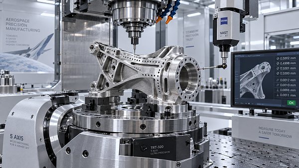
Engine Block CNC Milling Gets Unstable When Fixturing Looks Good on Paper
Publication Date
author
When cnc milling for automotive engine blocks turns unstable, the root cause is rarely as simple as a weak clamp. For engineers, operators, buyers, and decision-makers, the real issue often lies in the gap between fixturing theory and shop-floor dynamics. This article examines why a setup that looks correct on paper can still fail under load, and how data-driven analysis prevents costly machining errors.
Why a Stable Fixture Model Can Still Fail During Engine Block CNC Milling
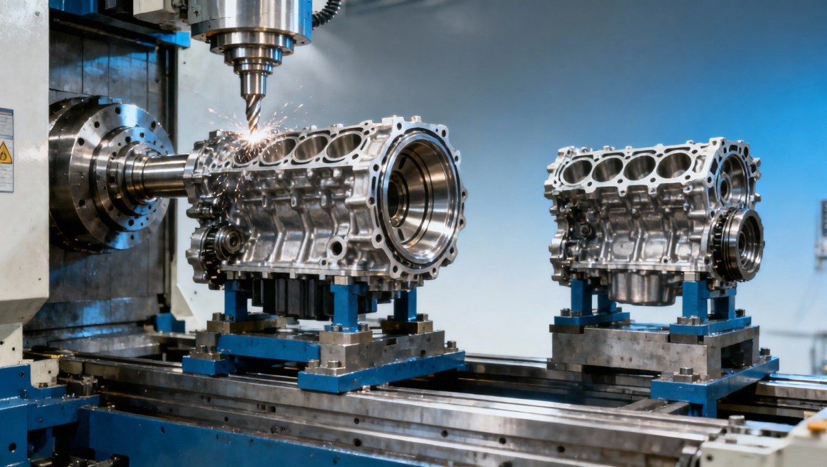
In precision machining, a fixture can satisfy drawing logic, clamping force calculations, and access requirements, yet still become unstable once the spindle starts cutting. Engine block CNC milling is especially sensitive because the part is large, ribbed, locally thin, and full of interrupted surfaces. A setup that appears rigid in a CAD review may behave very differently under dynamic load, thermal drift, and tool engagement changes across a 20–60 minute cycle.
This matters to more than process engineers. Operators need predictable cutting behavior, procurement teams need reliable supplier capability signals, and business leaders need confidence that scrap, rework, and delivery risk are controlled before launch. In automotive and broader hard-tech manufacturing, instability is not just a shop-floor inconvenience. It can disrupt PPAP timing, distort cost models, and delay downstream assembly validation.
A common mistake is treating fixturing as a static holding problem. In reality, engine block machining is a system problem involving workholding, cutter path, machine dynamics, datum transfer, and material condition. If any one variable shifts outside an acceptable process window, chatter, dimensional scatter, taper, or poor surface finish can appear even when the clamp layout looks ideal on paper.
At TechStat Vanguard, the useful question is not whether a fixture “looks strong.” The useful question is whether the entire machining system stays stable across 3 categories of stress: mechanical load, thermal variation, and repeatability over batch production. Parameters do not lie, and tolerances dictate success far more than marketing claims about rigidity.
Where paper-based fixture logic usually breaks down
Most unstable engine block CNC milling setups fail in one of 4 ways. First, the clamping points are structurally valid but poorly aligned with actual cutting force vectors. Second, the fixture supports the casting in nominal geometry, but not in the condition created by residual stress release. Third, the datum strategy works for roughing but loses control during finishing. Fourth, machine-tool dynamics amplify a minor weakness into visible instability.
- Static clamping force is sufficient, but local compliance near thin walls or deck areas allows micro-movement under interrupted cuts.
- Locator placement follows drawing datums, yet actual stock variation from castings creates inconsistent seating from part to part.
- Fixture mass is adequate, but the contact stack-up includes wear, chips, or hydraulic lag that reduces repeatability over 50–200 parts.
- Toolpath entry, radial engagement, or spindle speed pushes the system into a vibration zone that was never considered in fixture review.
That is why data-driven machining benchmarks matter. TSV focuses on separating real process capability from brochure language. If a supplier cannot explain how it validates fixture repeatability, thermal behavior, and datum consistency across typical batch ranges, then “robust workholding” is only a claim, not an engineering conclusion.
What Actually Makes Engine Block CNC Milling Unstable on the Shop Floor?
Unstable milling usually starts with a mismatch between nominal fixture theory and real cutting conditions. Engine blocks often combine deep pockets, cylinder deck planes, bearing bore relationships, and gasket-critical surfaces in one part family. This creates changing tool overhang, varying chip loads, and multiple stiffness zones in the same cycle. Even a well-designed fixture can be exposed when the process moves from roughing to semi-finishing to finishing.
Residual stress is one of the least discussed variables in procurement discussions. Cast iron and aluminum engine blocks can release stress after stock removal, especially when roughing removes material asymmetrically. A fixture may hold the original casting shape correctly, but after 1.5 mm–4 mm of material comes off key regions, the part may relax. If support points no longer match the evolved geometry, the next operation sees positional shift rather than true repeatability.
Another cause is clamping sequence. It is not enough to specify clamp force ranges such as 8 kN–20 kN. The order, timing, and confirmation of clamping matter. In hydraulic fixtures, pressure loss, delayed actuation, or uneven contact can create subtle preload differences. Operators may compensate manually, but manual correction introduces batch-to-batch variability that is invisible in design review and painful in production.
Machine behavior also plays a major role. A fixture validated on one horizontal machining center can become unstable on another platform with different spindle characteristics, axis acceleration, or pallet interface stiffness. The result is a familiar complaint: the same setup sheet works on paper, but one machine produces chatter bands, another produces taper, and a third holds tolerance for only the first 10 parts after tool change.
The dynamic variables teams often underestimate
For research teams and buyers comparing machining partners, these variables deserve direct attention:
The table shows why unstable engine block CNC milling is rarely caused by a single obvious defect. It is usually the accumulation of small mismatches. For decision-makers, this is the key procurement lesson: ask how a supplier validates process windows over time, not just how the fixture is designed on day one.
Why operators detect the problem before reports do
Operators typically notice instability first through sound, chip shape, spindle load fluctuation, or changing witness marks. These are early warnings that often appear 5–15 parts before dimensional failure is formally measured. Yet many organizations still separate operator feedback from process engineering. That is inefficient. In a mature machining system, operator observation should feed directly into fixture maintenance, toolpath review, and inspection frequency plans.
TSV’s engineering-first perspective is simple: if instability can be heard, seen, or measured, it should be tracked as process data. Whether the end market is automotive, aerospace, robotics, or medical-grade precision machining, the principle is the same. Noise-free decision-making starts by converting symptoms into measurable variables.
How to Diagnose the Gap Between Fixture Design and Machining Reality
Diagnosis should follow a structured sequence rather than isolated trial-and-error. Many teams lose 2–4 weeks changing clamps, feeds, and inserts without proving root cause. A better approach is to test the stability chain in stages: part seating, clamping consistency, machine response, toolpath load, and thermal repeatability. This reduces guesswork and shortens supplier qualification cycles.
Start with part seating. If cast stock variation is significant, use blue-check, contact mapping, or repeat loading studies to see whether all supports engage consistently. A fixture that fully supports one casting may rock slightly on another from the same lot. That difference can be enough to shift deck flatness or side-face position beyond tolerance once aggressive milling begins.
Next, confirm clamping repeatability, not just nominal force. Force verification at a single moment is incomplete. What matters is whether the fixture reaches the same condition every cycle over 30, 50, or 100 repetitions. Pneumatic and hydraulic systems should be checked for pressure decay, uneven response, and confirmation delays. Mechanical systems should be checked for wear, thread condition, and contact point damage.
Then review the cutting process itself. If instability only appears in certain operations, the fixture may not be the first cause. Tool overhang, cutter pitch, spindle speed bands, radial width of cut, and approach strategy may be exciting a structural mode. A setup can become stable simply by changing engagement patterns or splitting one heavy pass into 2 lighter passes, especially on thin-wall or deck-adjacent features.
A practical 5-step diagnostic checklist
- Verify seating repeatability across at least 10 consecutive loads using the same fixture and part family.
- Measure clamp response consistency and confirm no meaningful drift across a normal production window.
- Track dimensional results before and after major stock removal to identify stress-release behavior.
- Compare spindle load patterns and surface signatures across machines, tools, and tool life stages.
- Separate fixture-induced error from toolpath-induced vibration by changing only one variable per test cycle.
This method helps every stakeholder. Researchers gain a cleaner root-cause map. Operators get actionable process adjustments. Buyers can evaluate whether a machining supplier manages engineering reality rather than simply quoting capacity. Executives get fewer late-stage surprises in launch planning.
Which signals should procurement teams request from suppliers?
Procurement rarely needs raw machine diagnostics for every project, but it does need evidence of process control. A capable supplier should explain how it monitors fixture wear, seating contamination, first-off versus steady-state variation, and reaction plans when stability shifts. The goal is not more paperwork. The goal is better risk visibility before awarding complex engine block CNC milling work.
This type of evaluation aligns with TSV’s core role as a data-driven hard-tech filter. Instead of asking who sounds confident, ask who can define process limits, verification intervals, and recovery actions in engineering terms.
What Buyers and Decision-Makers Should Check Before Approving a Milling Supplier
For procurement and executive teams, unstable engine block CNC milling is a commercial risk as much as a technical one. A low initial quote can become expensive when instability causes scrap, tool consumption spikes, delayed inspection loops, and repeated fixture modifications. Supplier selection should therefore examine process maturity, not only machine count or unit price.
A practical review should cover 5 decision dimensions: fixture strategy, machine-platform suitability, control plan quality, engineering response speed, and compliance readiness. In sectors that overlap with aerospace, medical, or high-reliability industrial systems, buyers may also look for disciplined traceability and process documentation practices consistent with broader quality expectations such as ISO 9001, AS9100, or ISO 13485 environments where applicable.
Lead time also deserves closer scrutiny. A supplier may promise samples in 7–15 days, but if fixture proving, process capability review, and corrective loops are not included in that schedule, the timeline is incomplete. For new engine block milling projects, realistic readiness often requires staged validation: fixturing review, trial cuts, dimensional confirmation, and repeatability checks before stable production release.
Budget discussions should include the cost of instability prevention. Spending more on fixture verification, probing logic, or process simulation may lower overall cost per accepted part. This is where engineering-led procurement decisions outperform price-only sourcing.
A short procurement checklist for unstable milling risk
- Request evidence of how the supplier handles cast variation, not just nominal CAD geometry.
- Confirm whether fixture validation includes repeat loading and long-cycle checks, not only one-time setup approval.
- Ask how roughing, semi-finishing, and finishing are separated to control stress release and vibration sensitivity.
- Review the inspection plan for early-warning signals such as drift across shift start, mid-run, and post-tool-change conditions.
- Check whether operators, process engineers, and quality teams share a defined escalation path when chatter or dimensional trend changes appear.
Common sourcing mistakes that look efficient but increase risk
One mistake is assuming that a supplier experienced in general CNC milling will automatically manage engine block dynamics well. Large prismatic parts with demanding datum relationships are not the same as simpler housings. Another mistake is approving a process after a small sample run of 3–5 parts. That may prove machine access, but it does not prove stable production behavior over a meaningful batch.
A third mistake is separating technical review from purchasing review. If commercial teams negotiate lead time and cost without understanding process windows, they may unintentionally remove the very controls that keep the project stable. In complex machining, commercial efficiency depends on engineering honesty.
FAQ: Engine Block CNC Milling Instability, Fixturing, and Process Control
The questions below reflect common search intent from engineering researchers, machine operators, sourcing teams, and industrial decision-makers evaluating engine block CNC milling risk.
How do I know whether the fixture is really the problem?
Do not assume the fixture is the first root cause. Compare results by changing one variable at a time. If instability tracks with spindle speed bands, tool overhang, or engagement strategy, the cutting process may be the main driver. If instability follows loading sequence, seating inconsistency, or clamp response, the fixture is more likely involved. A controlled 3-stage test plan is usually more reliable than intuition alone.
What are the first warning signs before dimensions go out of tolerance?
Early signals often include changing sound, visible chatter marks, altered chip shape, unstable spindle load, or finish variation on the same feature. These may appear 5–15 parts before formal nonconformance. Smart shops treat operator observations as data inputs and increase inspection frequency when those signals appear.
Can stronger clamping solve unstable engine block CNC milling?
Not always. More clamping force can reduce movement, but it can also distort the part, especially in thinner or stress-sensitive regions. The goal is balanced support and consistent seating, not maximum force. In many cases, locator strategy, support placement, or toolpath adjustment is more effective than simply increasing clamp load from one range to a higher one.
What delivery questions should buyers ask before placing an order?
Ask for the timeline of fixture proving, sample validation, dimensional review, and production readiness. Clarify whether the quoted lead time includes repeatability checks, not just first articles. For new or difficult parts, separate prototype timing from stable batch timing. That distinction reduces surprises in production planning and supplier qualification.
Why Choose a Data-Driven Engineering Partner for Fixturing and Milling Decisions
When fixturing looks right on paper but engine block CNC milling still becomes unstable, the solution is not more marketing language. The solution is disciplined analysis of parameters, tolerances, machine behavior, and supplier process control. That is where TechStat Vanguard creates value for global engineering teams, procurement leaders, and industrial decision-makers navigating hard-tech sourcing noise.
TSV approaches machining questions the same way it approaches robotics, aerospace systems, sensors, and edge AI benchmarking: by filtering out vague claims and focusing on measurable engineering truth. For precision machining benchmarks, that means asking how stability is proven, how tolerance risk is monitored, and how supplier capability is separated from presentation quality.
If you are evaluating engine block CNC milling capability, you can consult TSV for practical decision support around fixture logic, supplier comparison, tolerance-risk review, expected validation stages, and process benchmarking language for RFQs and technical specifications. Useful discussions typically include parameter confirmation, machining route assessment, delivery-window realism, quality control checkpoints, and documentation expectations for regulated or high-reliability sectors.
For teams preparing a sourcing decision, a supplier audit, or a specification sheet, contact TSV to clarify 4 high-impact topics: fixturing risk factors, process stability indicators, qualification requirements, and benchmarking criteria for vendor selection. In a market crowded with claims, engineering truth is still the most efficient path to lower trial-and-error cost and faster trust-building across the supply chain.
Search News
Hot Articles
- Carbon Fiber StructuresHow to Specify Aerospace Carbon Fiber Assemblies for Lightweight, Load-Bearing PartsJul 11, 2026
- Machine VisionXiaomi, Alibaba DAMO Academy Drive Open-Source Robotics Model Ecosystem, Lowering Algorithm Development Barriers for Overseas SMEs Adopting Chinese Robotics SolutionsMar 30, 2026
- Cobots & ArmsShanxi 'AI+' Conference Showcases Embodied Intelligence with Multinational Buyer Engagement: Key Industry ImplicationsMar 30, 2026
Popular Tags
Recommended News
 Jul 11, 2026How to Specify Aerospace Carbon Fiber Assemblies for Lightweight, Load-Bearing PartsAerospace carbon fiber assemblies: learn how to specify laminate design, load data, joining methods, and inspection controls for lighter, reliable load-bearing aerospace parts.Elena Rostova (UAV Systems Researcher)
 Mar 30, 2026Xiaomi, Alibaba DAMO Academy Drive Open-Source Robotics Model Ecosystem, Lowering Algorithm Development Barriers for Overseas SMEs Adopting Chinese Robotics SolutionsXiaomi & Alibaba DAMO Academy's open-source robotics models lower algorithm barriers for global SMEs. Boost efficiency in manufacturing, logistics & smart retail with ROS 2 compatible solutions.TSV Data Lab
 Mar 30, 2026Shanxi 'AI+' Conference Showcases Embodied Intelligence with Multinational Buyer Engagement: Key Industry ImplicationsShanxi 'AI+' Conference highlights embodied intelligence with Tesla, Ubtech & Jiantao showcasing multimodal robotics. 40+ global buyers validated tech on-site, creating new B2B channels for industrial automation & AI solutions.Chen Wei (Automation Lead Engineer)
 Mar 30, 2026Zhongguancun Unveils 6G Integrated Sensing-Computing-Intelligence Platform to Empower Embodied Robots for Global Industrial ApplicationsZhongguancun's new 6G platform revolutionizes industrial robotics with <10ms latency, empowering global automotive, logistics & port automation. Discover how this tech boosts China's smart manufacturing exports.TSV Data Lab
 Mar 30, 2026Mech-Mind Tianjin Embodied Intelligence R&D and Production Base Goes Live, Cutting Delivery Time by 20%–30% for Global Customized AMR+Vision SolutionsMech-Mind's Tianjin AMR+Vision production base cuts delivery time by 20%-30% for欧美 & Latin American markets. Discover how this PLd-certified facility accelerates customized robotics solutions for smart manufacturing and logistics.Chen Wei (Automation Lead Engineer)
 Mar 30, 2026Boao Forum Reveals 'Co-evolution of Big and Small Brains' Trend in Humanoid Robots, China's Embodied Intelligence Accelerates Adaptation to Overseas Manufacturing Service ScenariosDiscover how China's humanoid robots, featuring 'Co-evolution of Big and Small Brains,' are revolutionizing global manufacturing. Learn about Embodied Tian Gong 3.0's ISO compliance and overseas deployment at Boao Forum 2026.Chen Wei (Automation Lead Engineer)
 Mar 30, 2026China Railway Industrial Secures Patent for Embodied Robotics in Material Handling, Boosting High-Precision Delivery Capabilities for Overseas Infrastructure and Manufacturing ProjectsChina Railway Industrial's new patent for embodied robotics in material handling boosts high-precision delivery for global infrastructure & manufacturing. Discover how this innovation enhances logistics accuracy in automotive, rail transit & EPC projects.Chen Wei (Automation Lead Engineer)
 Oct 14, 2026Drone Frame Composites: Carbon Fiber vs. Fiberglass for Weight and StiffnessExplore drone structural materials composites: compare carbon fiber and fiberglass for weight, stiffness, cost, and antenna compatibility. Find the right material for your drone frame.Elena Rostova (UAV Systems Researcher)
 Oct 13, 2026Smart Cameras vs. PC-Based Machine Vision: Which Fits High-Speed Inspection?This industrial product comparison for machine vision weighs smart cameras vs. PC-based systems on latency, throughput, and cost. Discover your best fit for high-speed inspection.TSV Data Lab
 Oct 12, 2026How to Verify RoHS Compliance in Industrial Sensing Systems Before DeploymentRoHS compliant sensing systems: learn how to verify materials, supplier declarations, testing, and configuration controls before industrial deployment.TSV Data Lab
 Oct 11, 2026How Procurement-Oriented Content Taxonomy Improves B2B Buying JourneysProcurement-oriented content taxonomy streamlines B2B buying journeys with clearer evidence, supplier comparisons, risk visibility, and faster approvals.TSV Data Lab
 Oct 10, 2026How to Select a Machine Performance Monitoring Platform for OEE and Downtime ReductionMachine performance monitoring platform selection guide: validate machine states, OEE data, downtime reasons, integrations, and scalability to reduce losses with confidence.TSV Data Lab
 Oct 08, 2026How to Machine Inconel 625 Blades Without Heat Cracks or Edge ChippingInconel 625 blade machining guide: prevent heat cracks, edge chipping, chatter, and work hardening with proven tooling, cooling, fixturing, and inspection strategies.Dr. Marcus Vance
 Oct 07, 2026How to Evaluate an HMI Panel Distributor for Industrial Automation ProjectsHMI panel distributor evaluation guide: verify technical compatibility, traceability, supply reliability, lifecycle support, and total cost for automation projects.Victor Lin (Chief Software Architect)
 Oct 06, 2026Navigation Fault Tolerance Standards for AMRs: What Safety Teams Must VerifyNavigation fault tolerance standards: learn what AMR safety teams must verify, from localization loss and sensor faults to stopping distance, safe restart, and site-specific validation.Chen Wei (Automation Lead Engineer)
 Oct 05, 2026Calculating Edge Computing Total Cost of Ownership Across Distributed SitesEdge computing ownership cost explained: calculate deployment, energy, connectivity, security, remote support, and refresh costs across distributed sites.TSV Data Lab
 Oct 04, 2026CAD/CAM Benchmarking in the GCC: What Manufacturers Should Ask a ConsultantCAD CAM benchmark consultant GCC guide: learn the key questions manufacturers should ask to validate post-processors, workflows, machine performance, and production risk.Victor Lin (Chief Software Architect)
 Oct 03, 2026Selecting Automotive Radar Sensor Modules for ADAS Range, Resolution, and IntegrationAutomotive radar sensor module selection guide for ADAS: compare range, resolution, field of view, latency, and integration to build safer, reliable vehicle systems.TSV Data Lab
 Oct 02, 2026How to Qualify Machined Parts Suppliers for Hard Tech ProgramsHard tech supply chain machined parts demand rigorous supplier qualification. Learn how to assess capability, traceability, quality controls, and delivery resilience.Dr. Marcus Vance
 Oct 01, 2026How to Select an Outdoor Security Radar Sensor for Perimeter Detection?Outdoor security radar sensor selection guide: compare range, accuracy, false-alarm control, integration, and field testing for reliable perimeter detection.TSV Data Lab
 Sep 30, 2026How to Evaluate Solid-State LiDAR Hardware for Outdoor Autonomous VehiclesSolid state LiDAR hardware evaluation guide for outdoor autonomous vehicles—compare range, point-cloud quality, environmental resilience, integration, and safety.TSV Data Lab
 Sep 29, 2026ISO 9283 Repeatability: How to Evaluate Cobot Positioning PerformanceISO 9283 cobot repeatability explained: learn how payload, reach, approach direction, and test conditions affect positioning performance and cell capability.Chen Wei (Automation Lead Engineer)
 Oct 14, 2026How tight can micro machining aerospace tolerances be in production?Micro machining aerospace tolerances can reach low-micron levels in production. Learn what controls repeatability, inspection confidence, and flight-critical quality.Dr. Marcus Vance
 Oct 13, 2026How to keep an industrial robotic integration project on scheduleIndustrial robotic integration project management: keep automation on schedule with proven controls for interfaces, suppliers, FAT, commissioning, and change risk.Victor Lin (Chief Software Architect)