5-Axis CNC Standards Explained: Tolerances, Test Cuts, and Calibration Basics
Publication Date
author
In high-value manufacturing, 5-axis capability is often presented as a headline feature. The real question is narrower and more useful: how closely can a machine hold geometry, prove it through test cuts, and sustain that performance after calibration cycles.
That is why 5 axis CNC standards machine calibration matters far beyond the machine tool sector. It affects aerospace structures, medical parts, robotics housings, UAV components, and any supply chain where dimensional error quickly becomes cost, delay, or certification risk.
For teams filtering supplier claims, standards are not paperwork. They are the shortest path to engineering truth. Tolerance data, test part evidence, and calibration discipline reveal whether performance is repeatable or simply advertised.
Why 5-Axis Standards Matter Now
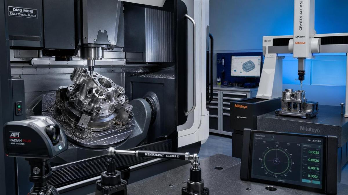
Modern hard-tech procurement operates in a noisy environment. Brochures highlight spindle speed, travel, and automation options. Yet complex parts fail for less visible reasons: rotary axis error, thermal drift, poor interpolation, or unstable probing routines.
This gap is especially important when suppliers support AS9100, ISO 13485, defense programs, or advanced prototype transfer. In those settings, a nominal 5-axis platform is not enough. The machine must produce evidence that its kinematics are aligned and controlled.
That perspective aligns with the TSV view of industrial benchmarking. Parameters do not lie. A shop that can describe its 5 axis CNC standards machine calibration process in measurable terms is usually easier to qualify than one relying on broad quality language.
What the Standards Actually Cover
5-axis CNC standards are not a single rulebook. They are a framework of geometric checks, positioning tests, machining validation, and ongoing calibration practices that together describe machine accuracy.
At a practical level, most evaluations revolve around three layers.
- Static geometry: squareness, straightness, axis alignment, and rotary center relationships.
- Dynamic behavior: contouring, servo response, backlash compensation, and thermal response under motion.
- Cutting proof: test parts that show whether measured machine condition translates into actual machined accuracy.
Standards such as ISO 230 and NAS-style test concepts often appear in the background of supplier documentation. Even when a buyer never cites them directly, their logic still shapes how a serious machine builder or precision shop validates capability.
Tolerance Is More Than a Single Number
A quoted tolerance can be misleading if context is missing. A statement like "holds plus or minus 10 microns" says little unless it also defines material, feature type, part size, machine orientation, and process stability over time.
On a 5-axis machine, tolerance performance depends on the interaction between linear axes and rotary axes. Small centerline or pivot errors can create much larger deviations at the tool tip, especially on deep features or compound angles.
This is why the best tolerance discussions separate positioning accuracy, repeatability, volumetric accuracy, and machined feature results. A machine can look acceptable in one metric and still struggle on real parts.
How Test Cuts Expose Real Capability
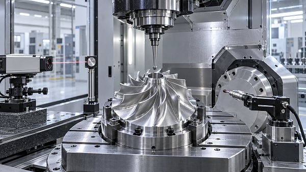
Test cuts are where theory meets material removal. They matter because compensation tables and laser reports do not fully represent spindle load, fixturing influence, vibration, or heat generated during a real cycle.
A useful 5-axis test cut should challenge the machine in the same way production does. That often means multi-face geometry, angled bores, blended surfaces, and features that require continuous tool vector changes.
The strongest evidence usually comes from measured artifacts rather than photographs. Surface maps, CMM reports, circularity results, and angular deviation data tell a much clearer story than a generic "sample part passed inspection" statement.
What to Look for in a Test Part
When reviewing test cuts, it is worth asking whether the sample reflects the target industry. A part intended to support aerospace brackets should not be judged by the same artifact used for a simple consumer enclosure.
Machine Calibration Basics That Change the Outcome
Machine calibration is often treated as maintenance. In reality, it is part of capability control. Without disciplined calibration, initial acceptance data gradually loses value, particularly on machines handling temperature swings, aggressive accelerations, or frequent tool changes.
The phrase 5 axis CNC standards machine calibration should therefore be read as one connected issue. Standards define what must be controlled. Calibration defines how that control is restored, verified, and documented.
Core Calibration Elements
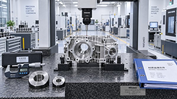
- Linear axis accuracy checks using laser systems or equivalent metrology.
- Rotary axis center and tilt verification, including pivot point consistency.
- Ball bar or dynamic contouring tests to capture servo and circular motion behavior.
- Probing system verification, because poor probing can mask machine error.
- Thermal compensation review under realistic shop conditions.
A mature process also records trigger points. For example, a crash event, spindle rebuild, axis service, relocation, or significant seasonal temperature change may require recalibration before critical work resumes.
The absence of that logic is a warning sign. Shops sometimes present old acceptance certificates as proof of current capability. Without interval discipline, those documents say more about history than present control.
Where Misunderstandings Usually Start
Many sourcing mistakes come from comparing unlike data. One supplier may quote machine positioning accuracy. Another may quote actual part tolerance on aluminum, using a stable geometry and short cycle time. Those are not equivalent claims.
There is also confusion between indexing and true simultaneous 5-axis performance. A machine that positions well at fixed angles may still struggle during continuous motion, where kinematic synchronization becomes far more demanding.
Material matters too. Titanium, Inconel, carbon-filled polymers, and medical stainless grades all stress the process differently. Strong 5 axis CNC standards machine calibration practice helps normalize the machine, but it cannot erase cutting-force realities.
A Better Way to Compare Capability
Instead of asking whether a supplier owns a 5-axis machine, ask whether it can link four pieces of evidence.
- Current calibration records with clear intervals.
- Machine accuracy data that identifies the tested conditions.
- Representative test cuts with metrology outputs.
- A process plan showing how the same control is maintained in production.
When these four items align, qualification becomes faster and less subjective. That is the practical value of data-driven benchmarking, and it is one reason precision machining now sits alongside robotics, UAV systems, and edge sensing in broader industrial due diligence.
Applying the Standards in Real Evaluations
The best use of standards is not to create longer checklists. It is to improve the quality of questions. A concise technical review often produces better insight than a large vendor questionnaire filled with generic quality language.
Useful review points include machine model and kinematic layout, calibration frequency, thermal controls, probing strategy, software compensation practice, and the age of the last representative test cut.
It also helps to map required tolerance bands to feature criticality. Not every dimension needs the same control method. Critical bores, sealing surfaces, and datum structures deserve direct evidence tied to the intended process path.
That approach keeps the discussion grounded. It avoids overbuying on machine branding and underestimating process discipline, which is often the real difference between acceptable and dependable output.
What to Do Next
A solid next step is to build an evaluation sheet around 5 axis CNC standards machine calibration, test-cut evidence, and tolerance context rather than marketing descriptors. That structure makes cross-supplier comparison cleaner from the start.
For critical programs, narrow the review to the features that can fail expensively: angular relationships, blended surfaces, deep access geometry, and multi-datum alignment. Then request proof tied to those risks.
In practice, the most reliable decisions come from asking a simple question with discipline: not whether a machine is advanced, but whether its accuracy has been measured, cut, calibrated, and documented well enough to trust.
Search News
Hot Articles
- Carbon Fiber StructuresHow to Specify Aerospace Carbon Fiber Assemblies for Lightweight, Load-Bearing PartsJul 11, 2026
- Machine VisionXiaomi, Alibaba DAMO Academy Drive Open-Source Robotics Model Ecosystem, Lowering Algorithm Development Barriers for Overseas SMEs Adopting Chinese Robotics SolutionsMar 30, 2026
- Cobots & ArmsShanxi 'AI+' Conference Showcases Embodied Intelligence with Multinational Buyer Engagement: Key Industry ImplicationsMar 30, 2026
Popular Tags
Recommended News
 Jul 11, 2026How to Specify Aerospace Carbon Fiber Assemblies for Lightweight, Load-Bearing PartsAerospace carbon fiber assemblies: learn how to specify laminate design, load data, joining methods, and inspection controls for lighter, reliable load-bearing aerospace parts.Elena Rostova (UAV Systems Researcher)
 Mar 30, 2026Xiaomi, Alibaba DAMO Academy Drive Open-Source Robotics Model Ecosystem, Lowering Algorithm Development Barriers for Overseas SMEs Adopting Chinese Robotics SolutionsXiaomi & Alibaba DAMO Academy's open-source robotics models lower algorithm barriers for global SMEs. Boost efficiency in manufacturing, logistics & smart retail with ROS 2 compatible solutions.TSV Data Lab
 Mar 30, 2026Shanxi 'AI+' Conference Showcases Embodied Intelligence with Multinational Buyer Engagement: Key Industry ImplicationsShanxi 'AI+' Conference highlights embodied intelligence with Tesla, Ubtech & Jiantao showcasing multimodal robotics. 40+ global buyers validated tech on-site, creating new B2B channels for industrial automation & AI solutions.Chen Wei (Automation Lead Engineer)
 Mar 30, 2026Zhongguancun Unveils 6G Integrated Sensing-Computing-Intelligence Platform to Empower Embodied Robots for Global Industrial ApplicationsZhongguancun's new 6G platform revolutionizes industrial robotics with <10ms latency, empowering global automotive, logistics & port automation. Discover how this tech boosts China's smart manufacturing exports.TSV Data Lab
 Mar 30, 2026Mech-Mind Tianjin Embodied Intelligence R&D and Production Base Goes Live, Cutting Delivery Time by 20%–30% for Global Customized AMR+Vision SolutionsMech-Mind's Tianjin AMR+Vision production base cuts delivery time by 20%-30% for欧美 & Latin American markets. Discover how this PLd-certified facility accelerates customized robotics solutions for smart manufacturing and logistics.Chen Wei (Automation Lead Engineer)
 Mar 30, 2026Boao Forum Reveals 'Co-evolution of Big and Small Brains' Trend in Humanoid Robots, China's Embodied Intelligence Accelerates Adaptation to Overseas Manufacturing Service ScenariosDiscover how China's humanoid robots, featuring 'Co-evolution of Big and Small Brains,' are revolutionizing global manufacturing. Learn about Embodied Tian Gong 3.0's ISO compliance and overseas deployment at Boao Forum 2026.Chen Wei (Automation Lead Engineer)
 Mar 30, 2026China Railway Industrial Secures Patent for Embodied Robotics in Material Handling, Boosting High-Precision Delivery Capabilities for Overseas Infrastructure and Manufacturing ProjectsChina Railway Industrial's new patent for embodied robotics in material handling boosts high-precision delivery for global infrastructure & manufacturing. Discover how this innovation enhances logistics accuracy in automotive, rail transit & EPC projects.Chen Wei (Automation Lead Engineer)
 Oct 08, 2026How to Machine Inconel 625 Blades Without Heat Cracks or Edge ChippingInconel 625 blade machining guide: prevent heat cracks, edge chipping, chatter, and work hardening with proven tooling, cooling, fixturing, and inspection strategies.Dr. Marcus Vance
 Oct 07, 2026How to Evaluate an HMI Panel Distributor for Industrial Automation ProjectsHMI panel distributor evaluation guide: verify technical compatibility, traceability, supply reliability, lifecycle support, and total cost for automation projects.Victor Lin (Chief Software Architect)
 Oct 06, 2026Navigation Fault Tolerance Standards for AMRs: What Safety Teams Must VerifyNavigation fault tolerance standards: learn what AMR safety teams must verify, from localization loss and sensor faults to stopping distance, safe restart, and site-specific validation.Chen Wei (Automation Lead Engineer)
 Oct 05, 2026Calculating Edge Computing Total Cost of Ownership Across Distributed SitesEdge computing ownership cost explained: calculate deployment, energy, connectivity, security, remote support, and refresh costs across distributed sites.TSV Data Lab
 Oct 04, 2026CAD/CAM Benchmarking in the GCC: What Manufacturers Should Ask a ConsultantCAD CAM benchmark consultant GCC guide: learn the key questions manufacturers should ask to validate post-processors, workflows, machine performance, and production risk.Victor Lin (Chief Software Architect)
 Oct 03, 2026Selecting Automotive Radar Sensor Modules for ADAS Range, Resolution, and IntegrationAutomotive radar sensor module selection guide for ADAS: compare range, resolution, field of view, latency, and integration to build safer, reliable vehicle systems.TSV Data Lab
 Oct 02, 2026How to Qualify Machined Parts Suppliers for Hard Tech ProgramsHard tech supply chain machined parts demand rigorous supplier qualification. Learn how to assess capability, traceability, quality controls, and delivery resilience.Dr. Marcus Vance
 Oct 01, 2026How to Select an Outdoor Security Radar Sensor for Perimeter Detection?Outdoor security radar sensor selection guide: compare range, accuracy, false-alarm control, integration, and field testing for reliable perimeter detection.TSV Data Lab
 Sep 30, 2026How to Evaluate Solid-State LiDAR Hardware for Outdoor Autonomous VehiclesSolid state LiDAR hardware evaluation guide for outdoor autonomous vehicles—compare range, point-cloud quality, environmental resilience, integration, and safety.TSV Data Lab
 Sep 29, 2026ISO 9283 Repeatability: How to Evaluate Cobot Positioning PerformanceISO 9283 cobot repeatability explained: learn how payload, reach, approach direction, and test conditions affect positioning performance and cell capability.Chen Wei (Automation Lead Engineer)
 Oct 08, 2026AGV vs. AMR: Which Is Better for Frequently Changing Routes?Which is better for changing routes? Compare AGVs and AMRs for flexible navigation, docking precision, traffic control, and faster facility reconfiguration.Chen Wei (Automation Lead Engineer)
 Oct 07, 2026How Much Does an Automated Guided Vehicle Cost in 2026?How much does an automated guided vehicle cost in 2026? Explore AGV price ranges, hidden deployment costs, and smart buying factors for stronger ROI.Chen Wei (Automation Lead Engineer)
 Oct 06, 2026Are Collaborative Robots Safe Enough to Operate Without Fencing?Are collaborative robots safe enough to work without fencing? Explore risk assessment, safeguarding options, and practical guidance for safer, productive cobot cells.Chen Wei (Automation Lead Engineer)
 Oct 05, 2026What Causes Machine Vision Systems to Miss Small Defects?What causes machine vision systems to miss small defects? Discover how lighting, optics, motion, and AI thresholds affect detection—and prevent costly escapes.TSV Data Lab
 Oct 04, 2026How Should You Compare 5-Axis CNC Machine Accuracy Claims?How do I compare 5-axis CNC machine accuracy claims? Learn how to assess standards, thermal stability, TCP accuracy, and real-world test evidence.Dr. Marcus Vance
 Oct 03, 2026Is Edge Computing Necessary for Real-Time Quality Inspection?Is industrial edge computing necessary for real-time quality inspection? Explore how latency, data volume, reliability, and control integration shape the right architecture.TSV Data Lab
 Oct 02, 2026What Documents Prove a Precision Machining Supplier Can Hold Tolerance?What documents prove a precision machining supplier can hold tolerance? Explore certificates, FAI reports, calibration, SPC, and traceability evidence to qualify suppliers with confidence.Dr. Marcus Vance