What Should a SCADA System Include for a Water Treatment Plant?
Publication Date
author
During a turbidity rise, a pump trip, or an unexpected chlorine residual deviation, operators cannot afford to search through disconnected screens, handwritten logs, and delayed laboratory records. They need to see what changed, where it changed, and which response is safe before a minor process upset becomes a compliance or service issue.
So, what should a SCADA system include for a water treatment plant? At minimum, it should combine reliable real-time data acquisition, clear operator visualization, alarm management, controlled remote operation, historical records, reporting, cybersecurity, and resilient communications. The system should not merely display values; it should connect source-water conditions, treatment stages, equipment status, water-quality measurements, and operator actions into a traceable operating record.
Start with the treatment decisions the system must support
A SCADA specification often fails when it begins with screens or software licenses instead of operating decisions. Water treatment plants differ in source water, treatment process, staffing model, distribution arrangement, and regulatory obligations. Yet the questions operators face are usually practical:
- Is incoming water quality changing quickly enough to require a process adjustment?
- Are chemical feed rates matching actual flow and treatment demand?
- Has a filter reached a condition that requires backwash?
- Did a pump fail to start, trip on protection, or lose communication?
- Is a reservoir level approaching a limit that affects treatment or distribution?
- Which alarms need immediate response, and which can wait for planned maintenance?
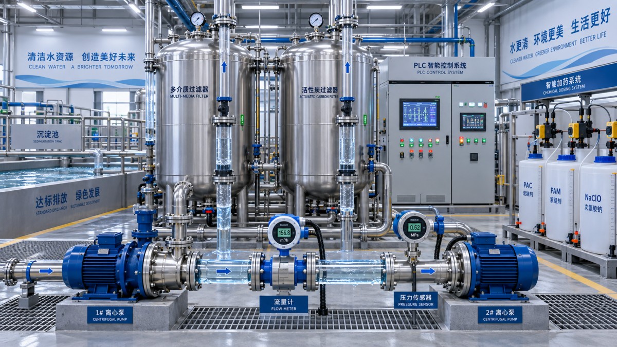
The SCADA system should be designed around those decisions. A raw-water intake may require close tracking of flow, pH, turbidity, conductivity, intake pump state, screen condition, and source-water level. A conventional treatment train may also require coagulation feed, flocculation equipment, sedimentation indicators, filter differential pressure, backwash sequencing, disinfectant residuals, clearwell level, and finished-water flow.
Not every process variable needs the same sampling rate, display priority, retention period, or alarm treatment. A high-high clearwell level and a routine motor runtime are both useful signals, but they serve different operational purposes. Defining this distinction early prevents overloaded screens and alarm lists that obscure genuinely urgent events.
Reliable field data: the foundation beneath every screen
SCADA quality depends first on instrument quality, signal integrity, and the logic that determines whether a reading is usable. The system should collect data from analyzers, level instruments, flowmeters, pressure transmitters, motor control centers, variable-frequency drives, valve actuators, package systems, and local controllers. In many plants, this involves a mix of PLCs, RTUs, intelligent electronic devices, and legacy equipment.
Each monitored point should have a clear engineering definition. That includes tag name, location, units, normal range, alarm limits, scaling, source device, update behavior, quality state, and the process reason for collecting it. Ambiguous tags create avoidable confusion during abnormal events. “Pump 2 Status” is less useful than distinct, understandable points for command, run feedback, fault feedback, local/remote mode, speed reference, actual speed, current, runtime, and permissive status.
Signal quality deserves visible treatment in the HMI. A value that is stale, overridden, out of range, manually entered, or lost due to communication failure should not look identical to a valid live measurement. Operators need to distinguish a true process condition from an instrumentation or network problem. For critical analyzers, the system may also need calibration status, analyzer fault indications, sample flow condition, and maintenance mode.
Operator displays should explain the process, not decorate it
An effective HMI provides situational awareness at several levels. The top-level overview should show the overall treatment process, current production condition, major alarms, key water-quality indicators, and important storage levels. From there, operators should be able to drill down into individual treatment areas, equipment groups, and detailed control loops without navigating through excessive screen layers.
Useful displays normally include:
- Process overview screens for intake, treatment trains, chemical systems, filters, clearwell storage, and high-service pumping.
- Equipment faceplates showing mode, state, commands, permissives, interlocks, feedback, faults, and maintenance information.
- Trend displays for comparing related variables, such as raw-water turbidity, coagulant dose, settled-water turbidity, and filter performance.
- Alarm views sorted by priority, time, treatment area, and current state.
- Manual control views with clear indication of who has control and whether local field control takes precedence.
- Maintenance-oriented screens for motor runtime, starts, vibration or temperature signals where available, and instrument health.
Color use should be disciplined. When every pipe, pump, valve, and label is brightly colored, genuine alarms become difficult to identify. Process graphics work better when normal conditions are visually quiet and abnormal states stand out clearly. Animation should convey meaningful status, such as flow direction, active equipment, valve position, or failed communication, rather than simply making the screen appear active.
Alarm management must lead to action
Water treatment facilities often accumulate alarms over time: analyzer limits, pump faults, communication losses, level thresholds, door contacts, drive warnings, flow deviations, and process sequence messages. Without rationalization, the result is alarm flooding. During a real upset, the operator may receive dozens of secondary notifications while the initiating problem is hidden in the list.
A well-configured SCADA alarm system assigns a priority based on consequence and required response, not on the technical importance of the signal alone. Each alarm should answer three questions: what has happened, why it matters, and what the operator should check first. The alarm message “Filter 3 DP High—Review Filter Loading and Backwash Availability” is more actionable than a generic point name and limit violation.
Alarm design should address deadbands, delays, latching behavior, suppression during known shutdown states, shelving rules, acknowledgement requirements, and escalation paths. For example, a low-flow alarm may need a short delay after pump startup to avoid nuisance annunciation. A chemical skid communication alarm may be expected during planned maintenance, but it should not be permanently disabled without an auditable reason.
Critical alarms should remain distinguishable from advisory notices. A loss of disinfectant residual signal, a high-high tank level, or a failed duty pump may require immediate intervention. A service reminder or routine analyzer maintenance message may be important, but it should not compete for attention in the same way.
Remote control needs defined boundaries and interlocks
Remote operation is one of the most valuable SCADA capabilities, especially when treatment sites, reservoirs, booster stations, or intake structures are geographically separated. It also introduces operational risk when command authority, equipment modes, and safety conditions are unclear.
Every controllable device should have a documented control philosophy. This normally defines whether it can be started, stopped, positioned, reset, or placed in automatic mode from SCADA; what local controls can override remote commands; which permissives must be true; and what happens after communication loss or controller restart.
Automatic sequences are particularly important for filter backwash, duty/standby pumping, chemical transfer, reservoir control, and generator-related load management. The SCADA layer may initiate or supervise a sequence, but protective interlocks and essential process logic are generally better retained in the local controller. A central server or WAN connection should not be the sole barrier preventing unsafe equipment operation.
Historian and reporting functions create operational traceability
A plant cannot investigate a water-quality deviation or equipment event using current values alone. The SCADA system should include historical storage for selected process points, alarms, operator commands, setpoint changes, equipment states, and system events. Retention and sampling requirements should be defined by the value of the data, not by a default database setting.
Fast-changing signals, such as pump pressure during a trip or filter backwash sequence states, may need event-based or short-interval collection. Slower variables can often be stored at longer intervals, provided meaningful changes are retained. Exception reporting and deadband settings must be chosen carefully; aggressive compression can make trends look smooth while hiding short-duration events that matter during troubleshooting.
Reports should reduce manual transcription without creating a false sense of certainty. Typical reports include daily production totals, source and finished-water quality summaries, chemical usage, filter run duration, backwash activity, pump runtime, energy-related operating data, alarm occurrence, and operator shift summaries. A report should make its data source and calculation basis clear. For example, flow totals must identify whether they are derived from a totalizer, integrated instantaneous flow, or manually validated record.
Audit trails are essential where users can change setpoints, alarm limits, operating modes, user accounts, or report inputs. The record should show the change, time, user identity, and previous and new values. This protects operational accountability and makes later review more efficient.
Communications architecture should tolerate real plant conditions
Water infrastructure often includes remote assets connected by radio, cellular, leased circuits, fiber, or mixed networks. A SCADA design should assume that communication interruptions will occur. Remote controllers need to continue performing their local control duties during a WAN outage, while the central system should clearly identify stale data and restore communications without creating uncontrolled command behavior.
Network design should separate operational technology from ordinary business traffic where practical. Managed switches, segmented network zones, firewall rules, secure remote access, account management, and logging are core requirements rather than optional additions. Wireless and remote links require particular care because exposure, bandwidth limits, and intermittent service can affect both security and availability.
Cybersecurity should also account for maintenance reality. Unmanaged shared accounts, undocumented remote access tools, obsolete workstations, and uncontrolled portable media can undermine an otherwise sound architecture. Access should be role-based, remote sessions should be controlled and recorded where appropriate, and patching should follow a tested process that respects operational uptime requirements.
Resilience is more than installing a backup server
Plants should identify which failures are tolerable, which require rapid recovery, and which must not interrupt core control. This assessment affects controller redundancy, server architecture, power protection, network paths, backup strategy, and spare hardware planning. Not every component needs duplication, but critical functions need a defined failure response.
At a minimum, consider loss of the SCADA server, loss of a local PLC, loss of network communication, loss of time synchronization, loss of power, and loss of a key analyzer. Operators should know what remains automatic, what becomes manual, which readings are no longer trustworthy, and how to return equipment to normal service. Time synchronization across controllers, workstations, historians, and alarm systems is particularly important when reconstructing event sequences.
Build the specification around verification, not feature lists
Before commissioning, define how each important function will be tested. A factory or site acceptance process should verify point mapping, scaling, alarm behavior, interlocks, role-based access, command feedback, communications-loss behavior, historian records, reporting calculations, backup restoration, and time stamps. Testing should include abnormal conditions, not only normal startup.
A useful SCADA system for a water treatment plant is therefore a connected operating environment: field data with visible quality, clear process graphics, actionable alarms, bounded remote control, historical evidence, secure communications, and tested recovery behavior. When those elements are specified together, the platform becomes a practical tool for running the plant rather than a collection of screens that only look complete during normal operation.
Search News
Hot Articles
- Carbon Fiber StructuresHow to Specify Aerospace Carbon Fiber Assemblies for Lightweight, Load-Bearing PartsJul 11, 2026
- Machine VisionXiaomi, Alibaba DAMO Academy Drive Open-Source Robotics Model Ecosystem, Lowering Algorithm Development Barriers for Overseas SMEs Adopting Chinese Robotics SolutionsMar 30, 2026
- Cobots & ArmsShanxi 'AI+' Conference Showcases Embodied Intelligence with Multinational Buyer Engagement: Key Industry ImplicationsMar 30, 2026
Popular Tags
Recommended News
 Jul 11, 2026How to Specify Aerospace Carbon Fiber Assemblies for Lightweight, Load-Bearing PartsAerospace carbon fiber assemblies: learn how to specify laminate design, load data, joining methods, and inspection controls for lighter, reliable load-bearing aerospace parts.Elena Rostova (UAV Systems Researcher)
 Mar 30, 2026Xiaomi, Alibaba DAMO Academy Drive Open-Source Robotics Model Ecosystem, Lowering Algorithm Development Barriers for Overseas SMEs Adopting Chinese Robotics SolutionsXiaomi & Alibaba DAMO Academy's open-source robotics models lower algorithm barriers for global SMEs. Boost efficiency in manufacturing, logistics & smart retail with ROS 2 compatible solutions.TSV Data Lab
 Mar 30, 2026Shanxi 'AI+' Conference Showcases Embodied Intelligence with Multinational Buyer Engagement: Key Industry ImplicationsShanxi 'AI+' Conference highlights embodied intelligence with Tesla, Ubtech & Jiantao showcasing multimodal robotics. 40+ global buyers validated tech on-site, creating new B2B channels for industrial automation & AI solutions.Chen Wei (Automation Lead Engineer)
 Mar 30, 2026Zhongguancun Unveils 6G Integrated Sensing-Computing-Intelligence Platform to Empower Embodied Robots for Global Industrial ApplicationsZhongguancun's new 6G platform revolutionizes industrial robotics with <10ms latency, empowering global automotive, logistics & port automation. Discover how this tech boosts China's smart manufacturing exports.TSV Data Lab
 Mar 30, 2026Mech-Mind Tianjin Embodied Intelligence R&D and Production Base Goes Live, Cutting Delivery Time by 20%–30% for Global Customized AMR+Vision SolutionsMech-Mind's Tianjin AMR+Vision production base cuts delivery time by 20%-30% for欧美 & Latin American markets. Discover how this PLd-certified facility accelerates customized robotics solutions for smart manufacturing and logistics.Chen Wei (Automation Lead Engineer)
 Mar 30, 2026Boao Forum Reveals 'Co-evolution of Big and Small Brains' Trend in Humanoid Robots, China's Embodied Intelligence Accelerates Adaptation to Overseas Manufacturing Service ScenariosDiscover how China's humanoid robots, featuring 'Co-evolution of Big and Small Brains,' are revolutionizing global manufacturing. Learn about Embodied Tian Gong 3.0's ISO compliance and overseas deployment at Boao Forum 2026.Chen Wei (Automation Lead Engineer)
 Mar 30, 2026China Railway Industrial Secures Patent for Embodied Robotics in Material Handling, Boosting High-Precision Delivery Capabilities for Overseas Infrastructure and Manufacturing ProjectsChina Railway Industrial's new patent for embodied robotics in material handling boosts high-precision delivery for global infrastructure & manufacturing. Discover how this innovation enhances logistics accuracy in automotive, rail transit & EPC projects.Chen Wei (Automation Lead Engineer)
 Oct 07, 2026How to Evaluate an HMI Panel Distributor for Industrial Automation ProjectsHMI panel distributor evaluation guide: verify technical compatibility, traceability, supply reliability, lifecycle support, and total cost for automation projects.Victor Lin (Chief Software Architect)
 Oct 06, 2026Navigation Fault Tolerance Standards for AMRs: What Safety Teams Must VerifyNavigation fault tolerance standards: learn what AMR safety teams must verify, from localization loss and sensor faults to stopping distance, safe restart, and site-specific validation.Chen Wei (Automation Lead Engineer)
 Oct 05, 2026Calculating Edge Computing Total Cost of Ownership Across Distributed SitesEdge computing ownership cost explained: calculate deployment, energy, connectivity, security, remote support, and refresh costs across distributed sites.TSV Data Lab
 Oct 04, 2026CAD/CAM Benchmarking in the GCC: What Manufacturers Should Ask a ConsultantCAD CAM benchmark consultant GCC guide: learn the key questions manufacturers should ask to validate post-processors, workflows, machine performance, and production risk.Victor Lin (Chief Software Architect)
 Oct 03, 2026Selecting Automotive Radar Sensor Modules for ADAS Range, Resolution, and IntegrationAutomotive radar sensor module selection guide for ADAS: compare range, resolution, field of view, latency, and integration to build safer, reliable vehicle systems.TSV Data Lab
 Oct 02, 2026How to Qualify Machined Parts Suppliers for Hard Tech ProgramsHard tech supply chain machined parts demand rigorous supplier qualification. Learn how to assess capability, traceability, quality controls, and delivery resilience.Dr. Marcus Vance
 Oct 01, 2026How to Select an Outdoor Security Radar Sensor for Perimeter Detection?Outdoor security radar sensor selection guide: compare range, accuracy, false-alarm control, integration, and field testing for reliable perimeter detection.TSV Data Lab
 Sep 30, 2026How to Evaluate Solid-State LiDAR Hardware for Outdoor Autonomous VehiclesSolid state LiDAR hardware evaluation guide for outdoor autonomous vehicles—compare range, point-cloud quality, environmental resilience, integration, and safety.TSV Data Lab
 Sep 29, 2026ISO 9283 Repeatability: How to Evaluate Cobot Positioning PerformanceISO 9283 cobot repeatability explained: learn how payload, reach, approach direction, and test conditions affect positioning performance and cell capability.Chen Wei (Automation Lead Engineer)
 Oct 07, 2026How Much Does an Automated Guided Vehicle Cost in 2026?How much does an automated guided vehicle cost in 2026? Explore AGV price ranges, hidden deployment costs, and smart buying factors for stronger ROI.Chen Wei (Automation Lead Engineer)
 Oct 06, 2026Are Collaborative Robots Safe Enough to Operate Without Fencing?Are collaborative robots safe enough to work without fencing? Explore risk assessment, safeguarding options, and practical guidance for safer, productive cobot cells.Chen Wei (Automation Lead Engineer)
 Oct 05, 2026What Causes Machine Vision Systems to Miss Small Defects?What causes machine vision systems to miss small defects? Discover how lighting, optics, motion, and AI thresholds affect detection—and prevent costly escapes.TSV Data Lab
 Oct 04, 2026How Should You Compare 5-Axis CNC Machine Accuracy Claims?How do I compare 5-axis CNC machine accuracy claims? Learn how to assess standards, thermal stability, TCP accuracy, and real-world test evidence.Dr. Marcus Vance
 Oct 03, 2026Is Edge Computing Necessary for Real-Time Quality Inspection?Is industrial edge computing necessary for real-time quality inspection? Explore how latency, data volume, reliability, and control integration shape the right architecture.TSV Data Lab
 Oct 02, 2026What Documents Prove a Precision Machining Supplier Can Hold Tolerance?What documents prove a precision machining supplier can hold tolerance? Explore certificates, FAI reports, calibration, SPC, and traceability evidence to qualify suppliers with confidence.Dr. Marcus Vance
 Oct 01, 2026Can a Machining Supplier Meet Aerospace Fatigue Testing Requirements?Can a machining supplier meet aerospace fatigue testing requirements? Learn the traceability, process control, and test evidence needed for reliable aerospace parts.Dr. Marcus Vance
 Sep 30, 2026Which Industrial Robot Specifications Matter for High-Precision Assembly?Which industrial robot specifications matter most for high-precision assembly? Explore repeatability, accuracy, stiffness, vibration, calibration, and force control for reliable yields.Chen Wei (Automation Lead Engineer)