Integrated CAD CAM Software Comparison: Which Features Matter for 5-Axis CNC Workflows?
Publication Date
author
Integrated CAD CAM Software Comparison: Which Features Matter for 5-Axis CNC Workflows?
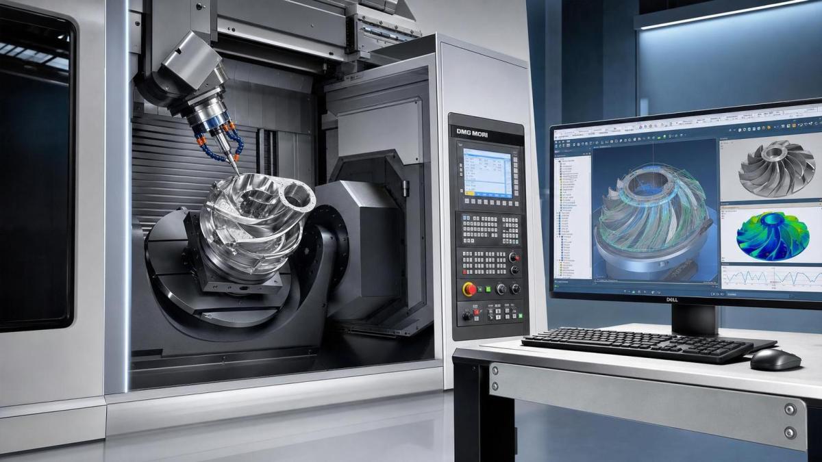
For project managers overseeing complex 5-axis machining programs, choosing integrated CAD CAM software is no longer just a technical decision. It directly shapes lead times, programming speed, toolpath quality, and communication across engineering and production.
That shift has become more visible as part complexity rises. Aerospace brackets, medical components, turbine parts, and UAV structures all demand tighter coordination between design changes and machining execution.
In that environment, integrated CAD CAM software matters because disconnected systems create delay. Files move slowly, revisions get missed, and programmers spend too much time rebuilding geometry or validating unstable toolpaths.
The better comparison is not about brand language. It is about measurable workflow value: fewer handoffs, better collision control, stronger post-processing, and clearer revision traceability under real 5-axis CNC conditions.
Why Integrated CAD CAM Software Changes 5-Axis Performance
A 5-axis program is rarely just a programming task. It sits inside a chain of design updates, tooling choices, fixture constraints, machine limits, and inspection requirements.
When CAD and CAM are fully connected, design intent carries forward with less friction. Surface changes, hole edits, stock updates, and datum changes can flow directly into manufacturing preparation.
This also reduces the hidden cost of translation. Neutral formats help, but they often lose feature intelligence, model history, or assembly context that affects machining decisions.
For complex programs, integrated CAD CAM software gives three practical advantages:
- Faster response to engineering change orders.
- Better consistency between model, setup, and toolpath.
- Less manual repair before simulation and posting.
That does not guarantee the best result. Some platforms are tightly integrated but weak in machine control, verification, or multi-axis finishing logic. That is where feature-level evaluation becomes critical.
The Core Features That Actually Matter
Many software comparisons focus on interface polish or generic automation claims. For 5-axis CNC work, the stronger signal is how the system behaves under unstable geometry, tight clearances, and revision-heavy schedules.
1. Associative model-to-toolpath updates
This should be near the top of any integrated CAD CAM software checklist. When a model changes, toolpaths should update predictably without forcing a full rebuild.
What matters is not just update speed. It is whether containment boundaries, avoidance surfaces, hole recognition, and machining regions stay reliable after revision.
2. Native 5-axis toolpath strategies
Look beyond simple positional indexing. Strong integrated CAD CAM software should support true simultaneous 5-axis machining for swarf, blade, impeller, port, and multi-surface finishing workflows.
The important question is whether tool axis control stays stable on difficult surfaces. Sudden tilting, unnecessary retracts, and poor smoothing usually show up later as cycle time loss or surface defects.
3. Collision detection with machine context
Basic holder collision checks are not enough. Real evaluation requires simulation against the full machine envelope, axis limits, fixtures, stock state, and spindle orientation.
This is especially important for high-value parts. A software platform that detects gouges but ignores machine kinematics still leaves significant production risk on the table.
4. Post-processor maturity
Integrated CAD CAM software can look impressive during demos, then fail at the post stage. That usually appears as rotary misalignment, poor code readability, inefficient output, or fragile support for specific controls.
A mature post framework should handle machine-specific behavior cleanly. It should also be maintainable when new fixtures, probing routines, or controller updates are introduced.
5. In-process verification and stock awareness
Stock-aware verification helps programmers avoid air cutting, buried tools, and leftover material in deep or wrapped features. This affects both machining confidence and quoting accuracy.
For shops handling precision contracts, this level of verification also supports a more defensible process record. That aligns with data-driven procurement and engineering review expectations.
How to Compare Platforms Without Getting Lost in Demos
Software demos are often clean because the sample part is clean. Real programs are not. They involve imported geometry, rushed revisions, awkward reach conditions, and machine-specific exceptions.
A more reliable integrated CAD CAM software evaluation uses the same part family your team already struggles with. That could be a thin-wall aluminum housing, a blisk-style form, or a fixture-limited titanium component.
During comparison, score each platform against operational questions:
- How quickly can a programmer move from revised geometry to verified code?
- How stable are the 5-axis toolpaths after local feature changes?
- Does simulation reflect the real machine configuration?
- How much post editing is still required at the control?
- Can another programmer reopen and understand the setup without guesswork?
Those questions shift the discussion from feature lists to workflow resilience. That is usually where the strongest purchasing signal appears.
A Practical Feature Comparison Framework
The table below is a useful way to compare integrated CAD CAM software options during shortlisting. It keeps attention on engineering outcomes instead of presentation quality.
This kind of scorecard is especially useful when multiple stakeholders are involved. Engineering, production, and procurement rarely define value in exactly the same way.
Common Buying Mistakes in Integrated CAD CAM Software Selection
One common mistake is treating integrated CAD CAM software as a license purchase only. In practice, value depends on implementation depth, post customization, training quality, and internal process discipline.
Another mistake is overvaluing broad capability and undervaluing repeatability. A platform may support many toolpaths on paper, yet still perform poorly on the exact parts your team machines every week.
There is also a governance risk. If templates, libraries, tool assemblies, and machine definitions are not standardized, even strong software can produce inconsistent programming output.
A more disciplined decision process usually includes:
- A test on representative 5-axis parts.
- Proof of machine-specific post support.
- Verification of revision handling inside current workflows.
- A realistic estimate of onboarding time and support load.
What a Strong Final Decision Looks Like
The best integrated CAD CAM software choice is usually the one that improves process stability fastest. That means fewer programming loops, cleaner updates, more reliable machine simulation, and less post-stage uncertainty.
For teams working in precision manufacturing, that standard fits a broader shift toward evidence-based selection. It also reflects the TSV view that parameters, tolerances, and repeatable outcomes carry more weight than software marketing language.
When comparing integrated CAD CAM software, focus on the features that directly change engineering execution. If a platform cannot protect revision integrity, machine realism, and 5-axis toolpath stability, the claimed efficiency gains will be hard to realize.
A practical next step is simple: shortlist two or three systems, run the same demanding part through each workflow, and measure programming hours, simulation exceptions, post edits, and prove-out risk before making the final call.
Search News
Hot Articles
- Carbon Fiber StructuresHow to Specify Aerospace Carbon Fiber Assemblies for Lightweight, Load-Bearing PartsJul 11, 2026
- Machine VisionXiaomi, Alibaba DAMO Academy Drive Open-Source Robotics Model Ecosystem, Lowering Algorithm Development Barriers for Overseas SMEs Adopting Chinese Robotics SolutionsMar 30, 2026
- Cobots & ArmsShanxi 'AI+' Conference Showcases Embodied Intelligence with Multinational Buyer Engagement: Key Industry ImplicationsMar 30, 2026
Popular Tags
Recommended News
 Jul 11, 2026How to Specify Aerospace Carbon Fiber Assemblies for Lightweight, Load-Bearing PartsAerospace carbon fiber assemblies: learn how to specify laminate design, load data, joining methods, and inspection controls for lighter, reliable load-bearing aerospace parts.Elena Rostova (UAV Systems Researcher)
 Mar 30, 2026Xiaomi, Alibaba DAMO Academy Drive Open-Source Robotics Model Ecosystem, Lowering Algorithm Development Barriers for Overseas SMEs Adopting Chinese Robotics SolutionsXiaomi & Alibaba DAMO Academy's open-source robotics models lower algorithm barriers for global SMEs. Boost efficiency in manufacturing, logistics & smart retail with ROS 2 compatible solutions.TSV Data Lab
 Mar 30, 2026Shanxi 'AI+' Conference Showcases Embodied Intelligence with Multinational Buyer Engagement: Key Industry ImplicationsShanxi 'AI+' Conference highlights embodied intelligence with Tesla, Ubtech & Jiantao showcasing multimodal robotics. 40+ global buyers validated tech on-site, creating new B2B channels for industrial automation & AI solutions.Chen Wei (Automation Lead Engineer)
 Mar 30, 2026Zhongguancun Unveils 6G Integrated Sensing-Computing-Intelligence Platform to Empower Embodied Robots for Global Industrial ApplicationsZhongguancun's new 6G platform revolutionizes industrial robotics with <10ms latency, empowering global automotive, logistics & port automation. Discover how this tech boosts China's smart manufacturing exports.TSV Data Lab
 Mar 30, 2026Mech-Mind Tianjin Embodied Intelligence R&D and Production Base Goes Live, Cutting Delivery Time by 20%–30% for Global Customized AMR+Vision SolutionsMech-Mind's Tianjin AMR+Vision production base cuts delivery time by 20%-30% for欧美 & Latin American markets. Discover how this PLd-certified facility accelerates customized robotics solutions for smart manufacturing and logistics.Chen Wei (Automation Lead Engineer)
 Mar 30, 2026Boao Forum Reveals 'Co-evolution of Big and Small Brains' Trend in Humanoid Robots, China's Embodied Intelligence Accelerates Adaptation to Overseas Manufacturing Service ScenariosDiscover how China's humanoid robots, featuring 'Co-evolution of Big and Small Brains,' are revolutionizing global manufacturing. Learn about Embodied Tian Gong 3.0's ISO compliance and overseas deployment at Boao Forum 2026.Chen Wei (Automation Lead Engineer)
 Mar 30, 2026China Railway Industrial Secures Patent for Embodied Robotics in Material Handling, Boosting High-Precision Delivery Capabilities for Overseas Infrastructure and Manufacturing ProjectsChina Railway Industrial's new patent for embodied robotics in material handling boosts high-precision delivery for global infrastructure & manufacturing. Discover how this innovation enhances logistics accuracy in automotive, rail transit & EPC projects.Chen Wei (Automation Lead Engineer)
 Oct 13, 2026Smart Cameras vs. PC-Based Machine Vision: Which Fits High-Speed Inspection?This industrial product comparison for machine vision weighs smart cameras vs. PC-based systems on latency, throughput, and cost. Discover your best fit for high-speed inspection.TSV Data Lab
 Oct 12, 2026How to Verify RoHS Compliance in Industrial Sensing Systems Before DeploymentRoHS compliant sensing systems: learn how to verify materials, supplier declarations, testing, and configuration controls before industrial deployment.TSV Data Lab
 Oct 11, 2026How Procurement-Oriented Content Taxonomy Improves B2B Buying JourneysProcurement-oriented content taxonomy streamlines B2B buying journeys with clearer evidence, supplier comparisons, risk visibility, and faster approvals.TSV Data Lab
 Oct 10, 2026How to Select a Machine Performance Monitoring Platform for OEE and Downtime ReductionMachine performance monitoring platform selection guide: validate machine states, OEE data, downtime reasons, integrations, and scalability to reduce losses with confidence.TSV Data Lab
 Oct 08, 2026How to Machine Inconel 625 Blades Without Heat Cracks or Edge ChippingInconel 625 blade machining guide: prevent heat cracks, edge chipping, chatter, and work hardening with proven tooling, cooling, fixturing, and inspection strategies.Dr. Marcus Vance
 Oct 07, 2026How to Evaluate an HMI Panel Distributor for Industrial Automation ProjectsHMI panel distributor evaluation guide: verify technical compatibility, traceability, supply reliability, lifecycle support, and total cost for automation projects.Victor Lin (Chief Software Architect)
 Oct 06, 2026Navigation Fault Tolerance Standards for AMRs: What Safety Teams Must VerifyNavigation fault tolerance standards: learn what AMR safety teams must verify, from localization loss and sensor faults to stopping distance, safe restart, and site-specific validation.Chen Wei (Automation Lead Engineer)
 Oct 05, 2026Calculating Edge Computing Total Cost of Ownership Across Distributed SitesEdge computing ownership cost explained: calculate deployment, energy, connectivity, security, remote support, and refresh costs across distributed sites.TSV Data Lab
 Oct 04, 2026CAD/CAM Benchmarking in the GCC: What Manufacturers Should Ask a ConsultantCAD CAM benchmark consultant GCC guide: learn the key questions manufacturers should ask to validate post-processors, workflows, machine performance, and production risk.Victor Lin (Chief Software Architect)
 Oct 03, 2026Selecting Automotive Radar Sensor Modules for ADAS Range, Resolution, and IntegrationAutomotive radar sensor module selection guide for ADAS: compare range, resolution, field of view, latency, and integration to build safer, reliable vehicle systems.TSV Data Lab
 Oct 02, 2026How to Qualify Machined Parts Suppliers for Hard Tech ProgramsHard tech supply chain machined parts demand rigorous supplier qualification. Learn how to assess capability, traceability, quality controls, and delivery resilience.Dr. Marcus Vance
 Oct 01, 2026How to Select an Outdoor Security Radar Sensor for Perimeter Detection?Outdoor security radar sensor selection guide: compare range, accuracy, false-alarm control, integration, and field testing for reliable perimeter detection.TSV Data Lab
 Sep 30, 2026How to Evaluate Solid-State LiDAR Hardware for Outdoor Autonomous VehiclesSolid state LiDAR hardware evaluation guide for outdoor autonomous vehicles—compare range, point-cloud quality, environmental resilience, integration, and safety.TSV Data Lab
 Sep 29, 2026ISO 9283 Repeatability: How to Evaluate Cobot Positioning PerformanceISO 9283 cobot repeatability explained: learn how payload, reach, approach direction, and test conditions affect positioning performance and cell capability.Chen Wei (Automation Lead Engineer)
 Oct 13, 2026How to keep an industrial robotic integration project on scheduleIndustrial robotic integration project management: keep automation on schedule with proven controls for interfaces, suppliers, FAT, commissioning, and change risk.Victor Lin (Chief Software Architect)
 Oct 12, 2026What should be included in predictive maintenance pricing for factories?Predictive maintenance pricing for factories: compare sensors, software, integration, support, and total cost to secure measurable uptime gains and avoid hidden expenses.TSV Data Lab
 Oct 11, 2026How payload and reach change the cost of an industrial robotCost of industrial robot systems depends heavily on payload and reach. Learn how sizing, torque, tooling, safety, and lifecycle factors shape smarter automation investments.Chen Wei (Automation Lead Engineer)