Aerospace machining process optimization starts with these fixes
Publication Date
author
Aerospace machining process optimization is no longer a marginal efficiency play—it is a strategic requirement for controlling tolerance risk, delivery stability, and total production cost. In aerospace programs, small process errors scale into inspection delays, rework, scrap, and qualification setbacks. The fastest gains rarely come from buying new machines first. They usually begin with a disciplined review of setup control, tool behavior, thermal stability, data capture, and process capability. This article explains where aerospace machining process optimization should start when measurable improvement matters more than vague promises.
Why aerospace machining process optimization works best as a checklist
A checklist approach prevents teams from chasing symptoms. Cycle time loss, chatter, dimensional drift, and poor surface finish often share root causes. A structured review makes those causes visible.
It also supports objective benchmarking. That fits TSV’s engineering-first view: parameters matter, tolerance windows decide outcomes, and process claims should be backed by repeatable data.
For aerospace machining process optimization, the goal is not only speed. The goal is stable capability across first article inspection, repeat batches, difficult alloys, and compliance-driven traceability.
Start with these fixes in your aerospace machining process optimization plan
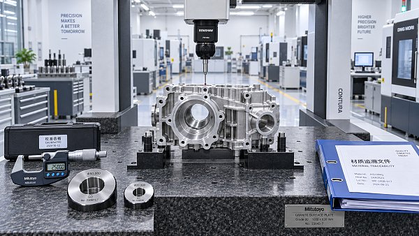
- Verify fixture repeatability before changing feeds and speeds. Poor location control creates false process variation and makes aerospace machining process optimization data unreliable.
- Map thermal drift across warm-up, long runs, and shift changes. Spindle growth and part temperature shifts often explain size movement better than tool wear alone.
- Measure actual tool life by feature, material, and cutter path. Generic tool-change intervals hide premature edge breakdown in titanium, Inconel, and thin-wall sections.
- Reduce unsupported reach wherever possible. Excessive stick-out amplifies vibration, degrades circularity, and limits any realistic aerospace machining process optimization effort.
- Standardize probing routines for datums, stock condition, and in-process correction. Reliable probing cuts setup variation and improves first-pass yield.
- Separate roughing and finishing strategies by stability target. High metal removal settings should not dictate the final surface or tolerance outcome.
- Audit coolant delivery pressure, direction, and cleanliness. Inadequate chip evacuation raises heat, damages edges, and distorts thin aerospace components.
- Track Cp and Cpk on critical characteristics, not only average dimensions. Aerospace machining process optimization depends on distribution control, not isolated good parts.
- Align CAM strategy with machine kinematics. Toolpaths that look efficient offline may overload rotary axes, create dwell marks, or trigger avoidable acceleration losses.
- Close the loop between machining, inspection, and nonconformance records. Repeating defects usually persist because process feedback arrives too late.
Where these fixes matter most
Thin-wall structural parts
Thin-wall brackets, frames, and housings magnify stress release and vibration. Here, aerospace machining process optimization should begin with workholding force, stock symmetry, and roughing sequence.
Finishing passes must be light, consistent, and thermally controlled. If wall movement appears late in the process, changing the final tool rarely solves the root issue.
Titanium and nickel-based alloys
These materials punish weak process discipline. Heat concentration, work hardening, and tool notch wear can destroy predictability. Aerospace machining process optimization in this case starts with engagement control and chip evacuation.
Shorter tools, stable radial engagement, and data-backed wear limits often outperform aggressive parameter changes. Tool cost should be judged against scrap risk and machine-hour loss.
Five-axis contour surfaces
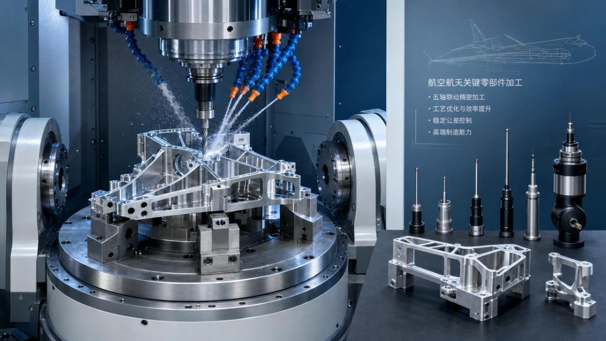
Complex impellers, blisks, and aerodynamic surfaces require coordinated axis behavior. Surface mismatch may come from machine dynamics, post-processing logic, or smoothing settings rather than cutter geometry.
Aerospace machining process optimization for five-axis work should compare programmed feed, actual feed, and axis load traces. That reveals where motion limits are shaping quality.
Commonly missed risks that slow improvement
Ignoring machine condition variation
Two nominally identical machines may produce different results because of spindle health, backlash, rotary calibration, or probing drift. Process transfer should never assume machine equality without evidence.
Treating inspection as a downstream activity
When metrology feedback arrives only after batch completion, aerospace machining process optimization becomes reactive. In-process inspection and feature-level trend analysis shorten the correction loop.
Overlooking raw material behavior
Residual stress, grain direction, hardness variation, and starting geometry can shift process capability. A stable NC program cannot fully compensate for unstable incoming stock.
Optimizing only for cycle time
A shorter cycle is not an improvement if it increases deburring, manual blending, or inspection failures. Aerospace machining process optimization must include total quality cost.
Use a simple execution model
A practical improvement cycle can stay compact and measurable. The following sequence works well when process noise is high and resources are limited.
- Select one part family with recurring scrap, long setup time, or unstable Cpk.
- Define three metrics only: first-pass yield, cycle time, and critical feature capability.
- Capture baseline data by machine, tool, shift, material lot, and inspection result.
- Change one variable group at a time: fixturing, toolpath, tooling, coolant, or probing.
- Confirm the result over multiple batches before standardizing the process sheet.
This method keeps aerospace machining process optimization tied to evidence. It also avoids the common failure mode of making several uncontrolled changes and learning nothing from the outcome.
Benchmarks worth tracking from the start
Not every metric deserves equal attention. For high-value aerospace components, early optimization should focus on indicators that reveal process stability and hidden cost.
Conclusion and next action
Aerospace machining process optimization should start with the factors that control repeatability: fixturing, thermal behavior, tool stability, probing, and feedback speed. Those fixes are usually cheaper and faster than capital replacement, yet they often unlock the biggest gains in yield and schedule reliability.
The next step is simple: choose one unstable part family, run the checklist, and baseline the four benchmarks above. Once the process is measured clearly, improvement stops being opinion-driven. It becomes an engineering decision grounded in traceable data—the only reliable foundation for aerospace machining process optimization.
Search News
Hot Articles
- Carbon Fiber StructuresHow to Specify Aerospace Carbon Fiber Assemblies for Lightweight, Load-Bearing PartsJul 11, 2026
- Machine VisionXiaomi, Alibaba DAMO Academy Drive Open-Source Robotics Model Ecosystem, Lowering Algorithm Development Barriers for Overseas SMEs Adopting Chinese Robotics SolutionsMar 30, 2026
- Cobots & ArmsShanxi 'AI+' Conference Showcases Embodied Intelligence with Multinational Buyer Engagement: Key Industry ImplicationsMar 30, 2026
Popular Tags
Recommended News
 Jul 11, 2026How to Specify Aerospace Carbon Fiber Assemblies for Lightweight, Load-Bearing PartsAerospace carbon fiber assemblies: learn how to specify laminate design, load data, joining methods, and inspection controls for lighter, reliable load-bearing aerospace parts.Elena Rostova (UAV Systems Researcher)
 Mar 30, 2026Xiaomi, Alibaba DAMO Academy Drive Open-Source Robotics Model Ecosystem, Lowering Algorithm Development Barriers for Overseas SMEs Adopting Chinese Robotics SolutionsXiaomi & Alibaba DAMO Academy's open-source robotics models lower algorithm barriers for global SMEs. Boost efficiency in manufacturing, logistics & smart retail with ROS 2 compatible solutions.TSV Data Lab
 Mar 30, 2026Shanxi 'AI+' Conference Showcases Embodied Intelligence with Multinational Buyer Engagement: Key Industry ImplicationsShanxi 'AI+' Conference highlights embodied intelligence with Tesla, Ubtech & Jiantao showcasing multimodal robotics. 40+ global buyers validated tech on-site, creating new B2B channels for industrial automation & AI solutions.Chen Wei (Automation Lead Engineer)
 Mar 30, 2026Zhongguancun Unveils 6G Integrated Sensing-Computing-Intelligence Platform to Empower Embodied Robots for Global Industrial ApplicationsZhongguancun's new 6G platform revolutionizes industrial robotics with <10ms latency, empowering global automotive, logistics & port automation. Discover how this tech boosts China's smart manufacturing exports.TSV Data Lab
 Mar 30, 2026Mech-Mind Tianjin Embodied Intelligence R&D and Production Base Goes Live, Cutting Delivery Time by 20%–30% for Global Customized AMR+Vision SolutionsMech-Mind's Tianjin AMR+Vision production base cuts delivery time by 20%-30% for欧美 & Latin American markets. Discover how this PLd-certified facility accelerates customized robotics solutions for smart manufacturing and logistics.Chen Wei (Automation Lead Engineer)
 Mar 30, 2026Boao Forum Reveals 'Co-evolution of Big and Small Brains' Trend in Humanoid Robots, China's Embodied Intelligence Accelerates Adaptation to Overseas Manufacturing Service ScenariosDiscover how China's humanoid robots, featuring 'Co-evolution of Big and Small Brains,' are revolutionizing global manufacturing. Learn about Embodied Tian Gong 3.0's ISO compliance and overseas deployment at Boao Forum 2026.Chen Wei (Automation Lead Engineer)
 Mar 30, 2026China Railway Industrial Secures Patent for Embodied Robotics in Material Handling, Boosting High-Precision Delivery Capabilities for Overseas Infrastructure and Manufacturing ProjectsChina Railway Industrial's new patent for embodied robotics in material handling boosts high-precision delivery for global infrastructure & manufacturing. Discover how this innovation enhances logistics accuracy in automotive, rail transit & EPC projects.Chen Wei (Automation Lead Engineer)
 Oct 06, 2026Navigation Fault Tolerance Standards for AMRs: What Safety Teams Must VerifyNavigation fault tolerance standards: learn what AMR safety teams must verify, from localization loss and sensor faults to stopping distance, safe restart, and site-specific validation.Chen Wei (Automation Lead Engineer)
 Oct 05, 2026Calculating Edge Computing Total Cost of Ownership Across Distributed SitesEdge computing ownership cost explained: calculate deployment, energy, connectivity, security, remote support, and refresh costs across distributed sites.TSV Data Lab
 Oct 04, 2026CAD/CAM Benchmarking in the GCC: What Manufacturers Should Ask a ConsultantCAD CAM benchmark consultant GCC guide: learn the key questions manufacturers should ask to validate post-processors, workflows, machine performance, and production risk.Victor Lin (Chief Software Architect)
 Oct 03, 2026Selecting Automotive Radar Sensor Modules for ADAS Range, Resolution, and IntegrationAutomotive radar sensor module selection guide for ADAS: compare range, resolution, field of view, latency, and integration to build safer, reliable vehicle systems.TSV Data Lab
 Oct 02, 2026How to Qualify Machined Parts Suppliers for Hard Tech ProgramsHard tech supply chain machined parts demand rigorous supplier qualification. Learn how to assess capability, traceability, quality controls, and delivery resilience.Dr. Marcus Vance
 Oct 01, 2026How to Select an Outdoor Security Radar Sensor for Perimeter Detection?Outdoor security radar sensor selection guide: compare range, accuracy, false-alarm control, integration, and field testing for reliable perimeter detection.TSV Data Lab
 Sep 30, 2026How to Evaluate Solid-State LiDAR Hardware for Outdoor Autonomous VehiclesSolid state LiDAR hardware evaluation guide for outdoor autonomous vehicles—compare range, point-cloud quality, environmental resilience, integration, and safety.TSV Data Lab
 Sep 29, 2026ISO 9283 Repeatability: How to Evaluate Cobot Positioning PerformanceISO 9283 cobot repeatability explained: learn how payload, reach, approach direction, and test conditions affect positioning performance and cell capability.Chen Wei (Automation Lead Engineer)
 Oct 06, 2026Are Collaborative Robots Safe Enough to Operate Without Fencing?Are collaborative robots safe enough to work without fencing? Explore risk assessment, safeguarding options, and practical guidance for safer, productive cobot cells.Chen Wei (Automation Lead Engineer)
 Oct 05, 2026What Causes Machine Vision Systems to Miss Small Defects?What causes machine vision systems to miss small defects? Discover how lighting, optics, motion, and AI thresholds affect detection—and prevent costly escapes.TSV Data Lab
 Oct 04, 2026How Should You Compare 5-Axis CNC Machine Accuracy Claims?How do I compare 5-axis CNC machine accuracy claims? Learn how to assess standards, thermal stability, TCP accuracy, and real-world test evidence.Dr. Marcus Vance
 Oct 03, 2026Is Edge Computing Necessary for Real-Time Quality Inspection?Is industrial edge computing necessary for real-time quality inspection? Explore how latency, data volume, reliability, and control integration shape the right architecture.TSV Data Lab
 Oct 02, 2026What Documents Prove a Precision Machining Supplier Can Hold Tolerance?What documents prove a precision machining supplier can hold tolerance? Explore certificates, FAI reports, calibration, SPC, and traceability evidence to qualify suppliers with confidence.Dr. Marcus Vance
 Oct 01, 2026Can a Machining Supplier Meet Aerospace Fatigue Testing Requirements?Can a machining supplier meet aerospace fatigue testing requirements? Learn the traceability, process control, and test evidence needed for reliable aerospace parts.Dr. Marcus Vance
 Sep 30, 2026Which Industrial Robot Specifications Matter for High-Precision Assembly?Which industrial robot specifications matter most for high-precision assembly? Explore repeatability, accuracy, stiffness, vibration, calibration, and force control for reliable yields.Chen Wei (Automation Lead Engineer)
 Sep 29, 2026How Do You Verify Servo Motor Torque Under Continuous Load?How do I verify servo motor torque under continuous load? Learn RMS torque checks, torque-speed limits, thermal derating, and real-machine testing.Chen Wei (Automation Lead Engineer)
 Oct 02, 2026ZD330 Software Configuration: Verifying Cut-List Import Before PurchaseZD330 software and machine configuration: verify cut-list imports, data mapping, labels, and workflow before purchase to reduce errors and choose with confidence.Victor Lin (Chief Software Architect)