UAV Flight Control Systems Vibration Isolation: Common Design Mistakes and How to Fix Them
Publication Date
author
Why vibration isolation decisions change once the aircraft enters real service
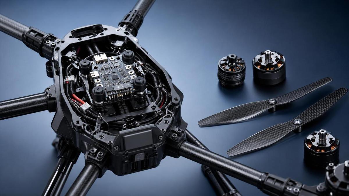
UAV flight control systems vibration isolation often fails quietly before any dramatic fault appears.
The early signs are usually small.
Position hold becomes less consistent.
IMU data looks noisy.
Mapping output drifts.
Connector fatigue appears sooner than expected.
That is why UAV flight control systems vibration isolation cannot be judged by soft-mount appearance alone.
In actual maintenance work, the right setup depends on propeller balance, motor harmonics, airframe stiffness, payload mass, and mission profile.
A multirotor used for crop spraying sees a different vibration signature from a survey aircraft carrying LiDAR.
A compact inspection drone also behaves differently from a heavy-lift platform flying long endurance cycles.
TechStat Vanguard consistently argues that parameters matter more than slogans.
That principle applies directly here.
Reliable vibration isolation starts with measured frequencies, mounting geometry, damping behavior, and long-term material stability.
Without that engineering discipline, repeated field repairs become normal, even when all parts are technically new.
The common mistake is treating every airframe as if the same mount will work
One of the most frequent errors in UAV flight control systems vibration isolation is copying a mount recipe from another platform.
The hardware may look similar, yet the excitation source is rarely identical.
A rigid carbon frame can transmit high-frequency energy very efficiently.
A molded composite body may damp some frequencies while amplifying others near the controller bay.
When a mount is too soft, the controller can enter low-frequency oscillation.
When it is too hard, motor and propeller vibration reaches the IMU almost unchanged.
The fix starts with identifying the dominant band.
Log raw sensor data, inspect FFT trends, and compare hover, climb, and cruise conditions.
More useful decisions come from flight data than from product descriptions claiming universal damping performance.
This is especially important in mixed fleets, where maintenance teams often assume interchangeable parts create interchangeable vibration behavior.
The material is only half the answer
Rubber durometer alone does not define good UAV flight control systems vibration isolation.
Mount thickness, preload, bolt torque, washer stack, and cable restraint change the final result.
A good damper can still fail if side loading compresses it unevenly.
Likewise, a clean bench installation can behave poorly after field wiring is tightened and pulls the controller tray off axis.
Different missions create different vibration priorities
In practical use, mission type changes what matters most.
The same UAV flight control systems vibration isolation approach should not be applied without adjustment across all operating environments.
This comparison matters because maintenance decisions become misleading when only catalog specifications are reviewed.
A mount that protects an autopilot in short survey flights may drift badly under liquid load transitions in spraying operations.
A rigid plate that works well for a compact inspection aircraft can overstress components on a larger heavy-lift frame.
Where field repairs usually go wrong
The most common repair error is replacing dampers without tracing the vibration source.
That may hide the symptom for a few sorties, but it rarely solves the root problem.
In UAV flight control systems vibration isolation, root causes often sit upstream.
- Propellers are statically balanced but not dynamically matched in service RPM.
- Motor shafts have minor runout that remains unnoticed during bench spin checks.
- Controller wiring is tied too tightly, forming a rigid vibration bridge.
- Fasteners loosen slightly, changing mount preload and resonance behavior.
- Foam pads absorb fuel mist, dust, or moisture and lose damping consistency.
Another frequent misjudgment is focusing only on hover.
Many vibration issues become worse during descent, aggressive yaw input, or payload transition.
That is why flight envelopes should be checked across the mission, not just during a clean test standup.
TSV’s data-first view is useful here.
The more repeatable the measurement method, the easier it becomes to separate airframe design limits from maintenance execution errors.
Environmental exposure changes the damping result
Temperature, UV exposure, chemicals, and dust all alter isolation performance over time.
This is often underestimated in fleets used outdoors every day.
Cold conditions can harden elastomers.
High summer heat can soften them and increase controller movement.
Chemical drift from agricultural work can shorten mount life even when the controller housing looks intact.
What a more reliable fix looks like in practice
A durable fix for UAV flight control systems vibration isolation usually combines mechanical correction with verification discipline.
It is rarely a one-part replacement job.
- Measure vibration before disassembly, using flight logs from several operating states.
- Inspect motors, propellers, shafts, and frame joints before selecting new mounts.
- Choose damping materials by frequency response, compression range, and environmental resistance.
- Control cable routing so wiring does not bypass the isolation layer.
- Recheck fastener torque after early flights, because settling changes preload.
- Compare sensor noise data before and after changes instead of relying on pilot feel alone.
For mapping aircraft, a slightly firmer mount can improve overall stability if it reduces low-frequency controller sway.
For heavy-lift aircraft, the better answer may be staged isolation between frame, avionics tray, and payload structure.
For smaller industrial drones, reducing cable stiffness and tray mass can outperform a softer damper.
The best fix depends on where the energy is entering the system and which frequencies are hurting control performance.
Before standardizing a solution, compare the conditions that actually matter
It helps to create a simple internal benchmark for UAV flight control systems vibration isolation.
That keeps future repairs from drifting into guesswork.
This kind of benchmark reflects the TSV mindset well.
Strip away generic claims, document measurable thresholds, and build decisions around repeatable engineering evidence.
The next step is to define vibration isolation by mission, not by habit
UAV flight control systems vibration isolation works best when it is treated as a mission-specific reliability problem.
The same hardware category can require different damping strategies once airframe structure, environment, and payload behavior change.
A more dependable path is to document the operating scenario, identify the dominant vibration source, verify mount behavior across the flight envelope, and review aging effects before standardizing any repair method.
That approach reduces repeat faults, protects sensor integrity, and extends controller life without relying on marketing language.
Where field data is limited, start with a narrow comparison set.
Log baseline vibration, compare at least two isolation setups, and define replacement criteria using measured drift rather than visual wear alone.
That is usually where better maintenance decisions begin.
Search News
Hot Articles
- Carbon Fiber StructuresHow to Specify Aerospace Carbon Fiber Assemblies for Lightweight, Load-Bearing PartsJul 11, 2026
- Machine VisionXiaomi, Alibaba DAMO Academy Drive Open-Source Robotics Model Ecosystem, Lowering Algorithm Development Barriers for Overseas SMEs Adopting Chinese Robotics SolutionsMar 30, 2026
- Cobots & ArmsShanxi 'AI+' Conference Showcases Embodied Intelligence with Multinational Buyer Engagement: Key Industry ImplicationsMar 30, 2026
Popular Tags
Recommended News
 Jul 11, 2026How to Specify Aerospace Carbon Fiber Assemblies for Lightweight, Load-Bearing PartsAerospace carbon fiber assemblies: learn how to specify laminate design, load data, joining methods, and inspection controls for lighter, reliable load-bearing aerospace parts.Elena Rostova (UAV Systems Researcher)
 Mar 30, 2026Xiaomi, Alibaba DAMO Academy Drive Open-Source Robotics Model Ecosystem, Lowering Algorithm Development Barriers for Overseas SMEs Adopting Chinese Robotics SolutionsXiaomi & Alibaba DAMO Academy's open-source robotics models lower algorithm barriers for global SMEs. Boost efficiency in manufacturing, logistics & smart retail with ROS 2 compatible solutions.TSV Data Lab
 Mar 30, 2026Shanxi 'AI+' Conference Showcases Embodied Intelligence with Multinational Buyer Engagement: Key Industry ImplicationsShanxi 'AI+' Conference highlights embodied intelligence with Tesla, Ubtech & Jiantao showcasing multimodal robotics. 40+ global buyers validated tech on-site, creating new B2B channels for industrial automation & AI solutions.Chen Wei (Automation Lead Engineer)
 Mar 30, 2026Zhongguancun Unveils 6G Integrated Sensing-Computing-Intelligence Platform to Empower Embodied Robots for Global Industrial ApplicationsZhongguancun's new 6G platform revolutionizes industrial robotics with <10ms latency, empowering global automotive, logistics & port automation. Discover how this tech boosts China's smart manufacturing exports.TSV Data Lab
 Mar 30, 2026Mech-Mind Tianjin Embodied Intelligence R&D and Production Base Goes Live, Cutting Delivery Time by 20%–30% for Global Customized AMR+Vision SolutionsMech-Mind's Tianjin AMR+Vision production base cuts delivery time by 20%-30% for欧美 & Latin American markets. Discover how this PLd-certified facility accelerates customized robotics solutions for smart manufacturing and logistics.Chen Wei (Automation Lead Engineer)
 Mar 30, 2026Boao Forum Reveals 'Co-evolution of Big and Small Brains' Trend in Humanoid Robots, China's Embodied Intelligence Accelerates Adaptation to Overseas Manufacturing Service ScenariosDiscover how China's humanoid robots, featuring 'Co-evolution of Big and Small Brains,' are revolutionizing global manufacturing. Learn about Embodied Tian Gong 3.0's ISO compliance and overseas deployment at Boao Forum 2026.Chen Wei (Automation Lead Engineer)
 Mar 30, 2026China Railway Industrial Secures Patent for Embodied Robotics in Material Handling, Boosting High-Precision Delivery Capabilities for Overseas Infrastructure and Manufacturing ProjectsChina Railway Industrial's new patent for embodied robotics in material handling boosts high-precision delivery for global infrastructure & manufacturing. Discover how this innovation enhances logistics accuracy in automotive, rail transit & EPC projects.Chen Wei (Automation Lead Engineer)
 Sep 29, 2026ISO 9283 Repeatability: How to Evaluate Cobot Positioning PerformanceISO 9283 cobot repeatability explained: learn how payload, reach, approach direction, and test conditions affect positioning performance and cell capability.Chen Wei (Automation Lead Engineer)
 Sep 29, 2026How Do You Verify Servo Motor Torque Under Continuous Load?How do I verify servo motor torque under continuous load? Learn RMS torque checks, torque-speed limits, thermal derating, and real-machine testing.Chen Wei (Automation Lead Engineer)
 Sep 28, 2026Spindle Runout Measurement in Germany: DIN Standards, Methods, and Acceptance LimitsSpindle runout measurement Germany: explore DIN standards, proven methods, acceptance limits, and audit-ready practices for reliable machining quality.Dr. Marcus Vance
 Sep 27, 2026How to Select Wall-Mount Edge Devices for Space-Constrained Factory NetworksWall mount edge devices for space-constrained factories: evaluate workload, thermal design, power resilience, cable access, and network reliability for smarter deployments.TSV Data Lab
 Sep 26, 2026Machining Tolerance Analysis: How to Set Limits That Meet Function and Cost TargetsMachining tolerance analysis: learn how to set functional limits, control tolerance stacks, reduce inspection risk, and balance precision with production cost.Dr. Marcus Vance
 Sep 25, 2026How to Evaluate an Industrial Infrastructure Data Platform for Multi-Site OperationsIndustrial infrastructure data platform evaluation guide for multi-site operations: compare data quality, edge resilience, interoperability, governance, and scalable proof-of-value criteria.Victor Lin (Chief Software Architect)
 Sep 24, 2026How to Select Machine Vision Optics for Accurate Inspection at Different Working DistancesMachine vision optics selection guide for accurate inspection at every working distance. Compare FOV, pixel scale, DOF, distortion, lighting, and telecentric options.TSV Data Lab
 Sep 23, 2026How to Evaluate a Machine Vision System Integrator for High-Speed Inspection LinesChoose a machine vision system integrator with proven expertise in high-speed inspection, reliable reject timing, robust optics, and measurable acceptance criteria.TSV Data Lab
 Sep 29, 2026How MES and OEE work together to identify production lossesMES and OEE work together to uncover hidden production losses, connect downtime, speed, and quality data, and drive smarter shop-floor improvements.Victor Lin (Chief Software Architect)
 Sep 28, 2026When is a SCADA API the right choice for connecting plant systems?SCADA API guide: learn when governed plant data integration improves traceability, security, and scalability—without compromising real-time control.Victor Lin (Chief Software Architect)
 Sep 27, 2026How SCADA data integration improves traceability across production linesSCADA data integration connects production-line data to improve traceability, accelerate quality investigations, and strengthen safety decisions.Victor Lin (Chief Software Architect)
 Sep 26, 2026What to define before starting SCADA integration planningSCADA integration planning starts with clear scope, control boundaries, data models, cybersecurity, and testing. Discover the definitions that reduce risk and costly rework.Victor Lin (Chief Software Architect)
 Sep 25, 2026How a smart factory with Industrial IoT reduces production blind spotsDiscover how a smart factory with Industrial IoT turns real-time machine, quality, and workflow data into actionable insights that reduce production blind spots and delivery risks.Victor Lin (Chief Software Architect)
 Sep 24, 2026When does Industrial IoT make smart manufacturing easier to scale?Smart manufacturing Industrial IoT scales when trusted data, interoperable systems, and secure workflows turn connected assets into measurable gains.TSV Data Lab
 Sep 23, 2026What drives ultra-precision machining cost at 1-micron tolerance?Ultra precision machining cost per part at 1 micron tolerance depends on process, material, metrology, and yield. Learn how to compare quotes confidently.Dr. Marcus Vance
 Sep 22, 2026Drone Engine-T550CC Applications: Build the UAV Power System Around the MissionAn application guide for Drone Engine-T550CC integration, covering payload planning, airframe matching, cooling, fuel, vibration, test procedures, documentation, and service preparation.Elena Rostova (UAV Systems Researcher)
 Sep 22, 2026How to Evaluate Industrial Edge Computing Vendors for Factory DeploymentIndustrial edge computing vendor evaluation guide for factories: compare latency, protocol fit, reliability, security, and lifecycle support before deployment.TSV Data Lab